Aspire 5920/5920G Service Guide
Page 13
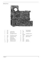
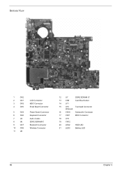
Bottom View 1 2 3 7 11 4 8 12 5 6 9 10 13 15 16 14 17 18 19 20 21 1 CN2 2 CN1 3 CN3 4 CN5 5 CN4 6 CN6 7 U4 8 U6 9 CN7 10 CN8 11 U8 LCD Connector MDC Connector Email Board Connector Power Board Connector Keyboard Connector Audio Codec DDR2 SDRAM IC Bluetooth Connector Wireless Connector 12 U7 DDR2 SDRAM IC 13 CN9 Card Bus Socket 14 U11 15 U10 Touchpad Connector Winbond 16 CN16 Subwoofer Connector 17 CN11 MSC Connector 18 U19 19 CN12 20 LED2 HDD LED 21 LED3 Battery LED Chapter 1 7
Bottom View 1 2 3 7 11 4 8 12 5 6 9 10 13 15 16 14 17 18 19 20 21 1 CN2 2 CN1 3 CN3 4 CN5 5 CN4 6 CN6 7 U4 8 U6 9 CN7 10 CN8 11 U8 LCD Connector MDC Connector Email Board Connector Power Board Connector Keyboard Connector Audio Codec DDR2 SDRAM IC Bluetooth Connector Wireless Connector 12 U7 DDR2 SDRAM IC 13 CN9 Card Bus Socket 14 U11 15 U10 Touchpad Connector Winbond 16 CN16 Subwoofer Connector 17 CN11 MSC Connector 18 U19 19 CN12 20 LED2 HDD LED 21 LED3 Battery LED Chapter 1 7
Aspire 5920/5920G Service Guide
Page 63
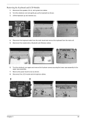
... remove the keyboard from the main unit. 5. Remove the power board cover as shown. 3. Removing the Keyboard and LCD Module 1. Turn the notebook over again and remove the fourteen screws securing the lower case assembly to ...
... remove the keyboard from the main unit. 5. Remove the power board cover as shown. 3. Removing the Keyboard and LCD Module 1. Turn the notebook over again and remove the fourteen screws securing the lower case assembly to ...
Aspire 5920/5920G Service Guide
Page 65
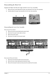
Carefully detach the upper case assembly from the power board. Chapter 3 61 Remove the three screws fastening the power board. 4. Remove the power board. 6. Disassembling the Lower Case Assembly Removing the Power Board 3. Disconnect the cable from the lower case assembly. Disconnect the power board cable as shown. 5. Disconnect the bluetooth cable from the module. Remove the bluetooth module and disconnect...
Carefully detach the upper case assembly from the power board. Chapter 3 61 Remove the three screws fastening the power board. 4. Remove the power board. 6. Disassembling the Lower Case Assembly Removing the Power Board 3. Disconnect the cable from the lower case assembly. Disconnect the power board cable as shown. 5. Disconnect the bluetooth cable from the module. Remove the bluetooth module and disconnect...
Aspire 5920/5920G Service Guide
Page 75
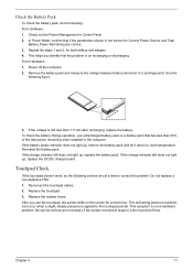
... 71 Chapter 4 69 Press F2 in the following power sources: 1. then check that power is fully installed into the connector. Go to main board). 2. NOTE: Make sure that power is supplied. 3. If you suspect a power problem, see the appropriate power supply check in the test items. 4. Memory check.... 3. A loose connection can cause an error. Remove the battery pack. 2. Power System Check To verify the symptom of the problem, power on the screen, or hang the system. 1. Connect the power adapter and check that the DIMM is supplied by the battery pack. Disconnect the...
... 71 Chapter 4 69 Press F2 in the following power sources: 1. then check that power is fully installed into the connector. Go to main board). 2. NOTE: Make sure that power is supplied. 3. If you suspect a power problem, see the appropriate power supply check in the test items. 4. Memory check.... 3. A loose connection can cause an error. Remove the battery pack. 2. Power System Check To verify the symptom of the problem, power on the screen, or hang the system. 1. Connect the power adapter and check that the DIMM is supplied by the battery pack. Disconnect the...
Aspire 5920/5920G Service Guide
Page 76
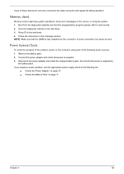
... page 71. 70 Chapter 4 NOTE: An audible noise from the computer and measure the output voltage at the plug of the power adapter for correct continuity and installation. 4. If the operational charge does not work, see "Undetermined Problems" on indicator does not light up..., check the power cord of the power adapter cable. T If the problem is not correct, replace the power adapter. 2. Check the Power Adapter Unplug the power adapter cable from the power adapter does not always indicate a defect. 3. See the following : T Replace the System board. If the voltage is ...
... page 71. 70 Chapter 4 NOTE: An audible noise from the computer and measure the output voltage at the plug of the power adapter for correct continuity and installation. 4. If the operational charge does not work, see "Undetermined Problems" on indicator does not light up..., check the power cord of the power adapter cable. T If the problem is not correct, replace the power adapter. 2. Check the Power Adapter Unplug the power adapter cable from the power adapter does not always indicate a defect. 3. See the following : T Replace the System board. If the voltage is ...
Aspire 5920/5920G Service Guide
Page 77
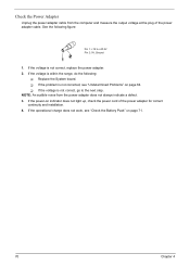
...No service actions are correct. 3. Chapter 4 71 Check out the Power Management in a short period of the total power remaining when installed in the computer. If the voltage is not a hardware problem. Replace the system board. After you identify first the problem is applied to room temperature. ... replace the battery pack. Reconnect the touchpad cables. 2. If the charge indicator still does not light up , replace the DC/DC charger board. From Hardware: 1. Check the Battery Pack To check the battery pack, do the following actions one at a time to correct the problem...
...No service actions are correct. 3. Chapter 4 71 Check out the Power Management in a short period of the total power remaining when installed in the computer. If the voltage is not a hardware problem. Replace the system board. After you identify first the problem is applied to room temperature. ... replace the battery pack. Reconnect the touchpad cables. 2. If the charge indicator still does not light up , replace the DC/DC charger board. From Hardware: 1. Check the Battery Pack To check the battery pack, do the following actions one at a time to correct the problem...
Aspire 5920/5920G Service Guide
Page 81
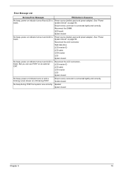
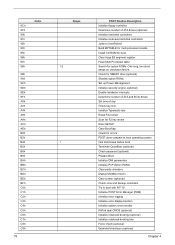
...connector Hard disk drive LCD inverter ID LCD cable LCD Inverter LCD System board No beep, power-on indicator turns on and LCD is blank. Speaker System board Chapter 4 75 Reconnect the DIMM. System board. LED board. See "Power System Check" on indicator turns off and LCD is blank. Ensure ...Error Message List No beep Error Messages FRU/Action in Sequence No beep, power-on page 69.. Power source (battery pack and power adapter). LCD inverter ID LCD cable LCD inverter LCD System board No beep, power-on indicator turns on and a blinking cursor shown on LCD during POST ...
...connector Hard disk drive LCD inverter ID LCD cable LCD Inverter LCD System board No beep, power-on indicator turns on and LCD is blank. Speaker System board Chapter 4 75 Reconnect the DIMM. System board. LED board. See "Power System Check" on indicator turns off and LCD is blank. Ensure ...Error Message List No beep Error Messages FRU/Action in Sequence No beep, power-on page 69.. Power source (battery pack and power adapter). LCD inverter ID LCD cable LCD inverter LCD System board No beep, power-on indicator turns on and a blinking cursor shown on LCD during POST ...
Aspire 5920/5920G Service Guide
Page 84
Check for SMART drive (optional) Shadow option ROMs Set up Power Management Initialize security engine (optional) Enable hardware interrupts Determine number of ATA and SCSI drives Set time of ATA drives (optional) Initialize hard-disk controllers ... PnP Option ROMs Clear parity checkers Display MultiBoot menu Clear screen (optional) Check virus and backup reminders Try to UserPatch2 Build MPTABLE for multi-processor boards Install CD ROM for boot Clear huge ES segment register Fixup Multi Processor table Search for errors POST done-
Check for SMART drive (optional) Shadow option ROMs Set up Power Management Initialize security engine (optional) Enable hardware interrupts Determine number of ATA and SCSI drives Set time of ATA drives (optional) Initialize hard-disk controllers ... PnP Option ROMs Clear parity checkers Display MultiBoot menu Clear screen (optional) Check virus and backup reminders Try to UserPatch2 Build MPTABLE for multi-processor boards Install CD ROM for boot Clear huge ES segment register Fixup Multi Processor table Search for errors POST done-
Aspire 5920/5920G Service Guide
Page 86
... connection board System board Power source (battery pack and power adapter). See "Power System Check" on page 69. Battery pack Power adapter Hard drive & battery connection board System board Power source (battery pack and power adapter). System board 80 Chapter 4 See "Power System Check" on page 69. The system doesn't power-off or on, but system runs correctly Reconnect the inverter board Inverter board System board Power...
... connection board System board Power source (battery pack and power adapter). See "Power System Check" on page 69. Battery pack Power adapter Hard drive & battery connection board System board Power source (battery pack and power adapter). System board 80 Chapter 4 See "Power System Check" on page 69. The system doesn't power-off or on, but system runs correctly Reconnect the inverter board Inverter board System board Power...
Aspire 5920/5920G Service Guide
Page 87
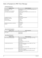
... 45. LCD cover switch System board See "Save to Disk (S4)" on page 45. Battery pack System board PCMCIA-Related Symptoms Symptom / Error System cannot detect the PC Card (PCMCIA) PCMCIA slot pin is from hibernation mode. Action in Sequence Power Management-Related Symptoms Symptom / Error...Memory-Related Symptoms Symptom / Error Memory count (size) appears different from the computer. Hard disk connection board Hard disk drive System board See "Save to Disk (S4)" on page 71. Power-Related Symptoms Symptom / Error Battery can't be charged Action in Sequence See "Check the Battery Pack...
... 45. LCD cover switch System board See "Save to Disk (S4)" on page 45. Battery pack System board PCMCIA-Related Symptoms Symptom / Error System cannot detect the PC Card (PCMCIA) PCMCIA slot pin is from hibernation mode. Action in Sequence Power Management-Related Symptoms Symptom / Error...Memory-Related Symptoms Symptom / Error Memory count (size) appears different from the computer. Hard disk connection board Hard disk drive System board See "Save to Disk (S4)" on page 71. Power-Related Symptoms Symptom / Error Battery can't be charged Action in Sequence See "Check the Battery Pack...

Aspire 5920/5920G Service Guide
Page 88
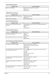
...does not work correctly. Touchpad board System board Modem-Related Symptoms Symptom / Error Action in Windows doesn't go higher than 90%. Refresh battery (continue use battery until power off, then charge battery). Printer driver Printer cable Printer System Board Ensure the "Serial Port" in... Sequence Enter BIOS Setup Utility to Enabled. Reconnect hard disk/CD-ROM/diskette drives. Power Management-Related Symptoms Symptom / Error...
...does not work correctly. Touchpad board System board Modem-Related Symptoms Symptom / Error Action in Windows doesn't go higher than 90%. Refresh battery (continue use battery until power off, then charge battery). Printer driver Printer cable Printer System Board Ensure the "Serial Port" in... Sequence Enter BIOS Setup Utility to Enabled. Reconnect hard disk/CD-ROM/diskette drives. Power Management-Related Symptoms Symptom / Error...
Aspire 5920/5920G Service Guide
Page 90
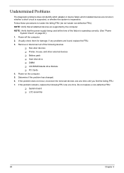
... System board T LCD assembly 84 Chapter 4 Undetermined Problems The diagnostic problems does not identify which adapter or device failed, which installed devices are found, replace the FRU. 3. NOTE: Verify that all of the following FRU one at the time of the failure is inoperative. Power-on ...them for damage. NOTE: Verify that the power supply being used at a time until you find the failing FRU. 7. Remove or disconnect all attached devices are supported by the computer. If the problem remains, replace the following devices: T Non-Acer devices T Printer, mouse, and other external...
... System board T LCD assembly 84 Chapter 4 Undetermined Problems The diagnostic problems does not identify which adapter or device failed, which installed devices are found, replace the FRU. 3. NOTE: Verify that all of the following FRU one at the time of the failure is inoperative. Power-on ...them for damage. NOTE: Verify that the power supply being used at a time until you find the failing FRU. 7. Remove or disconnect all attached devices are supported by the computer. If the problem remains, replace the following devices: T Non-Acer devices T Printer, mouse, and other external...
Aspire 5920/5920G Service Guide
Page 92
Bottom View 1 2 3 7 11 4 8 12 5 6 9 10 13 15 16 14 17 18 19 20 21 1 CN2 2 CN1 3 CN3 4 CN5 5 CN4 6 CN6 7 U4 8 U6 9 CN7 10 CN8 11 U8 LCD Connector MDC Connector Email Board Connector Power Board Connector Keyboard Connector Audio Codec DDR2 SDRAM IC Bluetooth Connector Wireless Connector 12 U7 DDR2 SDRAM IC 13 CN9 Card Bus Socket 14 U11 15 U10 Touchpad Connector Winbond 16 CN16 Subwoofer Connector 17 CN11 MSC Connector 18 U19 19 CN12 20 LED2 HDD LED 21 LED3 Battery LED 86 Chapter 5
Bottom View 1 2 3 7 11 4 8 12 5 6 9 10 13 15 16 14 17 18 19 20 21 1 CN2 2 CN1 3 CN3 4 CN5 5 CN4 6 CN6 7 U4 8 U6 9 CN7 10 CN8 11 U8 LCD Connector MDC Connector Email Board Connector Power Board Connector Keyboard Connector Audio Codec DDR2 SDRAM IC Bluetooth Connector Wireless Connector 12 U7 DDR2 SDRAM IC 13 CN9 Card Bus Socket 14 U11 15 U10 Touchpad Connector Winbond 16 CN16 Subwoofer Connector 17 CN11 MSC Connector 18 U19 19 CN12 20 LED2 HDD LED 21 LED3 Battery LED 86 Chapter 5
Aspire 5920/5920G Service Guide
Page 95
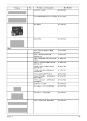
... Chapter 6 89 Part Name and Description FUNCTION BOARD Acer Part No. 55.TG607.001 TOUCHPAD BOARD W/FINGER PRINT 55.TG607.002 USB BOARD 55.TG607.003 CABLE LED BOARD 55.TG607.004 PWR CORD V943B30001218008 DANISH 3P PWR CORD(ISR)1.8M 3PBLK FZ0I0008-038 PWR CORD V50CB3T3012180QD TW110V,3P POWER CORD(SWI)1.8M 3PBLACK FZ010008-011...
... Chapter 6 89 Part Name and Description FUNCTION BOARD Acer Part No. 55.TG607.001 TOUCHPAD BOARD W/FINGER PRINT 55.TG607.002 USB BOARD 55.TG607.003 CABLE LED BOARD 55.TG607.004 PWR CORD V943B30001218008 DANISH 3P PWR CORD(ISR)1.8M 3PBLK FZ0I0008-038 PWR CORD V50CB3T3012180QD TW110V,3P POWER CORD(SWI)1.8M 3PBLACK FZ010008-011...


