
Quick Start Guide
Page 5
... instructions on the screen to use your Acer notebook, we have designed a set of guides: First off, the Just for meeting your new computer. Such instances are only contained in certain models of your mobile computing needs. Your guides To help you get started with language such as the AcerSystem User Guide mentioned below will run the Adobe Reader setup program first. The Quick Guide introduces you use Adobe Reader, access...
... instructions on the screen to use your Acer notebook, we have designed a set of guides: First off, the Just for meeting your new computer. Such instances are only contained in certain models of your mobile computing needs. Your guides To help you get started with language such as the AcerSystem User Guide mentioned below will run the Adobe Reader setup program first. The Quick Guide introduces you use Adobe Reader, access...
Quick Start Guide
Page 7
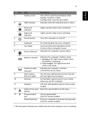
... computer cover is activated. 5 Power button Turns the computer on and off. 6 Keyboard For entering data into power-saving mode. (only for your computer. 7 Touchpad Touch-sensitive pointing device which functions like the left and right mouse buttons. Click buttons (left and right) The left and right buttons function like a computer mouse. 8 Power indicator1 Indicates the computer's power status. 9 10 11 12 13 P Battery indicator1 Indicates the computer's battery status. 1. Num Lock indicator Lights up . Fully charged: The light shows...
... computer cover is activated. 5 Power button Turns the computer on and off. 6 Keyboard For entering data into power-saving mode. (only for your computer. 7 Touchpad Touch-sensitive pointing device which functions like the left and right mouse buttons. Click buttons (left and right) The left and right buttons function like a computer mouse. 8 Power indicator1 Indicates the computer's power status. 9 10 11 12 13 P Battery indicator1 Indicates the computer's battery status. 1. Num Lock indicator Lights up . Fully charged: The light shows...
Quick Start Guide
Page 8
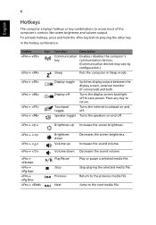
... Function Description Communication Enables / disables the computer's key communication devices. (Communication devices may vary by configuration.) Sleep Puts the computer in the hotkey combination. Turns the internal touchpad on and off Touchpad toggle Speaker toggle Switches display output between the display screen, external monitor (if connected) and both. Increases the sound volume. 6 English Hotkeys The computer employs hotkeys or key combinations to the next media file. To activate hotkeys, press and hold the key before pressing the other key in Sleep mode...
... Function Description Communication Enables / disables the computer's key communication devices. (Communication devices may vary by configuration.) Sleep Puts the computer in the hotkey combination. Turns the internal touchpad on and off Touchpad toggle Speaker toggle Switches display output between the display screen, external monitor (if connected) and both. Increases the sound volume. 6 English Hotkeys The computer employs hotkeys or key combinations to the next media file. To activate hotkeys, press and hold the key before pressing the other key in Sleep mode...

Quick Start Guide
Page 10
Connects to audio line-out devices line-out jack with (e.g., speakers, headphones). S/PDIF support Headphones/speaker/ Connects to a display device (e.g., external monitor, LCD projector). Accepts inputs from external microphones. USB 2.0 port Microphone jack Connect to an Ethernet 10/100/1000based network. Ethernet (RJ-45) port Connects to USB 2.0 devices (e.g., USB mouse, USB camera). HDMI port Supports high definition digital video connections. Ventilation slots External display (VGA) port Enable the computer to a Kensington-compatible computer security lock. 8 ...
Connects to audio line-out devices line-out jack with (e.g., speakers, headphones). S/PDIF support Headphones/speaker/ Connects to a display device (e.g., external monitor, LCD projector). Accepts inputs from external microphones. USB 2.0 port Microphone jack Connect to an Ethernet 10/100/1000based network. Ethernet (RJ-45) port Connects to USB 2.0 devices (e.g., USB mouse, USB camera). HDMI port Supports high definition digital video connections. Ventilation slots External display (VGA) port Enable the computer to a Kensington-compatible computer security lock. 8 ...
Service Guide
Page 7
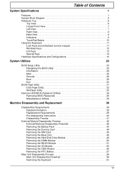
... Diagram 5 Notebook Tour 6 Top View 6 Closed Front View 7 Left View 7 Right View 8 Base View 9 Indicators 9 TouchPad Basics 10 Using the Keyboard 11 Lock Keys and embedded numeric keypad 11 Windows Keys 12 Hot Keys 13 Special Keys 14 Hardware Specifications and Configurations 15 System Utilities 23 BIOS Setup Utility 23 Navigating the BIOS Utility 23 Information 24 Main 25 Security 26 Boot 29 Exit 30 BIOS Flash Utility 31 DOS Flash Utility 32 WinFlash Utility 33 Remove HDD/BIOS Password Utilities 34 Removing BIOS Passwords 35 Miscellaneous Utilities...
... Diagram 5 Notebook Tour 6 Top View 6 Closed Front View 7 Left View 7 Right View 8 Base View 9 Indicators 9 TouchPad Basics 10 Using the Keyboard 11 Lock Keys and embedded numeric keypad 11 Windows Keys 12 Hot Keys 13 Special Keys 14 Hardware Specifications and Configurations 15 System Utilities 23 BIOS Setup Utility 23 Navigating the BIOS Utility 23 Information 24 Main 25 Security 26 Boot 29 Exit 30 BIOS Flash Utility 31 DOS Flash Utility 32 WinFlash Utility 33 Remove HDD/BIOS Password Utilities 34 Removing BIOS Passwords 35 Miscellaneous Utilities...

Service Guide
Page 8
... LCD Module 120 Replacing the Power Board 124 Replacing the Switch Board 125 Replacing the Upper Cover 126 Replacing the Keyboard 130 Replacing the Wireless LAN Module 131 Replacing the 3G Module 133 Replacing the DIMM Module 135 Replacing the Hard Disk Drive 136 Replacing the RTC Battery 138 Replacing the ODD Module 139 Replacing the Base Door 141 Replacing the SIM Card 142 Replacing the Battery 142 Replace the Dummy Card 143 Troubleshooting 145 Common Problems 145 Power On Issue 146 No Display Issue 147 Random Loss of BIOS Settings...
... LCD Module 120 Replacing the Power Board 124 Replacing the Switch Board 125 Replacing the Upper Cover 126 Replacing the Keyboard 130 Replacing the Wireless LAN Module 131 Replacing the 3G Module 133 Replacing the DIMM Module 135 Replacing the Hard Disk Drive 136 Replacing the RTC Battery 138 Replacing the ODD Module 139 Replacing the Base Door 141 Replacing the SIM Card 142 Replacing the Battery 142 Replace the Dummy Card 143 Troubleshooting 145 Common Problems 145 Power On Issue 146 No Display Issue 147 Random Loss of BIOS Settings...
Service Guide
Page 17
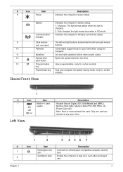
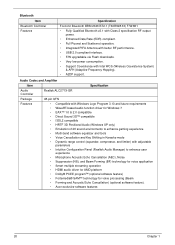
... optical disk from the drive. Only one card can operate at any given time. # 1 2 Chapter 1 1 2 3 4 56 7 Icon Item Kensington lock slot Ventilation slots Description Connects to remove/install the card. # Icon Item 8 Power Description Indicates the computer's power status. Fully charged: the light shows blue when in -1 card reader Left View Description Accepts Secure Digital (SD), MultiMediaCard (MMC), Memory Stick (MS), Memory Stick PRO (MS PRO), xDPicture Card (xD). Battery Communication indicator Indicates the computer's battery status. 1. Enable...
... optical disk from the drive. Only one card can operate at any given time. # 1 2 Chapter 1 1 2 3 4 56 7 Icon Item Kensington lock slot Ventilation slots Description Connects to remove/install the card. # Icon Item 8 Power Description Indicates the computer's power status. Fully charged: the light shows blue when in -1 card reader Left View Description Accepts Secure Digital (SD), MultiMediaCard (MMC), Memory Stick (MS), Memory Stick PRO (MS PRO), xDPicture Card (xD). Battery Communication indicator Indicates the computer's battery status. 1. Enable...

Service Guide
Page 19
... removal. Indicates the status of Wireless LAN communication. Locks the battery in AC mode. The battery indicator is visible even when the computer cover is active. HDD Num Lock Caps Lock Indicates when the hard disk drive is closed. NOTE: 1. Indicators The computer has several easy-to stay cool, even after prolonged use. 5 cooling fan Note: Do not cover or obstruct the opening the fan. 6 Battery release latch Releases the battery for reference only. Battery Wireless LAN Indicates the computer's battery...
... removal. Indicates the status of Wireless LAN communication. Locks the battery in AC mode. The battery indicator is visible even when the computer cover is active. HDD Num Lock Caps Lock Indicates when the hard disk drive is closed. NOTE: 1. Indicators The computer has several easy-to stay cool, even after prolonged use. 5 cooling fan Note: Do not cover or obstruct the opening the fan. 6 Battery release latch Releases the battery for reference only. Battery Wireless LAN Indicates the computer's battery...
Service Guide
Page 30
... with better RF performance. • USB 2.0 compliant interface. • F/W upgradable via Flash downloads. • Very low power consumption. • Support Coexistence with adjustable parameters • Intuitive Configuration Panel (Realtek Audio Manager) to enhance user experience • Microphone Acoustic Echo Cancellation (AEC), Noise • Suppression (NS), and Beam Forming (BF) technology for voice application • Smart multiple streaming operation • HDMI audio driver for AMD platform • Dolby...
... with better RF performance. • USB 2.0 compliant interface. • F/W upgradable via Flash downloads. • Very low power consumption. • Support Coexistence with adjustable parameters • Intuitive Configuration Panel (Realtek Audio Manager) to enhance user experience • Microphone Acoustic Echo Cancellation (AEC), Noise • Suppression (NS), and Beam Forming (BF) technology for voice application • Smart multiple streaming operation • HDMI audio driver for AMD platform • Dolby...

Service Guide
Page 31
... USB1.1 specifications • Supports multiple flash card interfaces, including SD/ MMC/xD/MS. • Supports single LUN • Supports both Windows and Mac OS Specifications SUYIN/ Chicony/ Liteon CMOS image sensor with WXGA (resolution 1280X800) USB Port 26.6cm ~ infinity 65.0±0.3 X 8.0±0.1 X 3.69+0.11/-0.2 mm Chapter 1 21 LAN Interface LAN Chipset Package Features Item Keyboard Item Type Total number of keypads Windows logo key Internal & external keyboard work simultaneously Features Specification ATHEROS...
... USB1.1 specifications • Supports multiple flash card interfaces, including SD/ MMC/xD/MS. • Supports single LUN • Supports both Windows and Mac OS Specifications SUYIN/ Chicony/ Liteon CMOS image sensor with WXGA (resolution 1280X800) USB Port 26.6cm ~ infinity 65.0±0.3 X 8.0±0.1 X 3.69+0.11/-0.2 mm Chapter 1 21 LAN Interface LAN Chipset Package Features Item Keyboard Item Type Total number of keypads Windows logo key Internal & external keyboard work simultaneously Features Specification ATHEROS...
Service Guide
Page 37
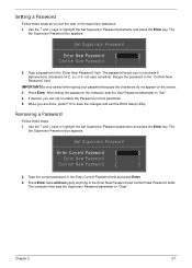
... Enter. 3. Press Enter. After setting the password, the computer sets the User Password parameter to highlight the Set Supervisor Password parameter and press the Enter key. When you set the user or the supervisor password: 1. Type the current password in the "Confirm New Password" field. The password length can opt to save the changes and exit the BIOS Setup Utility. Removing a Password Follow these steps as you are done, press F10 to enable the Password on the screen. 3. Use...
... Enter. 3. Press Enter. After setting the password, the computer sets the User Password parameter to highlight the Set Supervisor Password parameter and press the Enter key. When you set the user or the supervisor password: 1. Type the current password in the "Confirm New Password" field. The password length can opt to save the changes and exit the BIOS Setup Utility. Removing a Password Follow these steps as you are done, press F10 to enable the Password on the screen. 3. Use...

Service Guide
Page 38
... changes and exit the BIOS Setup Utility. The Set Password box appears. Type the current password in the Enter New Password field. If the verification is complete after the user presses Enter. If the current password entered does not match the actual current password, the screen will display as following message. Re-enter password. [Continue] 28 Chapter 2 Retype the password in the Confirm New Password field. 4. Set Supervisor Password Enter Current Password [ ] Enter New Password [ ] Confirm New Password [ ] 2. Changing a Password 1. Use the ↑ and ↓ keys...
... changes and exit the BIOS Setup Utility. The Set Password box appears. Type the current password in the Enter New Password field. If the verification is complete after the user presses Enter. If the current password entered does not match the actual current password, the screen will display as following message. Re-enter password. [Continue] 28 Chapter 2 Retype the password in the Confirm New Password field. 4. Set Supervisor Password Enter Current Password [ ] Enter New Password [ ] Confirm New Password [ ] 2. Changing a Password 1. Use the ↑ and ↓ keys...

Service Guide
Page 40
.../F6 Change Values F9 Setup Default Select Menu Enter Select SubMenu F10 Save and Exit The table below describes the parameters in this screen. Parameter Exit Saving Changes Exit Discarding Changes Load Setup Default Discard Changes Save Changes Description Exit System Setup and save or discard any changes you to CMOS. Load default values for all SETUP item. Exit The Exit screen allows you made and quit the BIOS Utility...
.../F6 Change Values F9 Setup Default Select Menu Enter Select SubMenu F10 Save and Exit The table below describes the parameters in this screen. Parameter Exit Saving Changes Exit Discarding Changes Load Setup Default Discard Changes Save Changes Description Exit System Setup and save or discard any changes you to CMOS. Load default values for all SETUP item. Exit The Exit screen allows you made and quit the BIOS Utility...

Service Guide
Page 69
Main Unit Disassembly Flowchart Remove External Modules before proceeding Remove Keyboard Remove Power Board Remove Upper Cover Remove Switch Board Remove LCD Module Remove I/O Board Remove Bluetooth Module Remove Mainboard Remove Thermal Module Remove Power Jack Assembly Remove SB Thermal Module Screw List Step Upper Cover Disassembly Remove CPU Screw M2.5*4Ni M2.0*3 Quantity 6 3 Part No. 86.EDM07.003 86.A08V7.005 Chapter 3 59
Main Unit Disassembly Flowchart Remove External Modules before proceeding Remove Keyboard Remove Power Board Remove Upper Cover Remove Switch Board Remove LCD Module Remove I/O Board Remove Bluetooth Module Remove Mainboard Remove Thermal Module Remove Power Jack Assembly Remove SB Thermal Module Screw List Step Upper Cover Disassembly Remove CPU Screw M2.5*4Ni M2.0*3 Quantity 6 3 Part No. 86.EDM07.003 86.A08V7.005 Chapter 3 59

Service Guide
Page 155
... 146 No Display Issue Page 147 LCD Failure Page 149 Internal Keyboard Failure Page 150 TouchPad Failure Page 151 Internal Speaker Failure Page 152 Internal Microphone Failure Page 153 USB Failure Page 155 Other Function Failure Page 155 4. If the Issue is still not resolved, see "Online Support Information" on page 255. Non-Acer products, prototype cards, or modified options can give false errors and...
... 146 No Display Issue Page 147 LCD Failure Page 149 Internal Keyboard Failure Page 150 TouchPad Failure Page 151 Internal Speaker Failure Page 152 Internal Microphone Failure Page 153 USB Failure Page 155 Other Function Failure Page 155 4. If the Issue is still not resolved, see "Online Support Information" on page 255. Non-Acer products, prototype cards, or modified options can give false errors and...

Service Guide
Page 157
...: START Replace LCD Panel and No Cable LCD Module OK? Make sure that the internal display is no power, see "LCD Failure" on page 146. 3. On this model). Connect an external monitor to No Power Power On ? Remove any stored power by checking at least one of the following occurs: • Fans start up • Status LEDs light up If there is selected. No troubleshooting step Ext. DDRAM module functional? If the POST or video appears on the external display...
...: START Replace LCD Panel and No Cable LCD Module OK? Make sure that the internal display is no power, see "LCD Failure" on page 146. 3. On this model). Connect an external monitor to No Power Power On ? Remove any stored power by checking at least one of the following occurs: • Fans start up • Status LEDs light up If there is selected. No troubleshooting step Ext. DDRAM module functional? If the POST or video appears on the external display...
Service Guide
Page 158
... power and data cables between devices. Check the display resolution is too dim at a time to correct the problem. 1. Minimize or close all Windows. See "Disassembly Process" on adjusting settings. If the computer boots correctly, add the devices one by one year old, replace the CMOS battery. 2. Remove the drives (see "Online Support Information" on page 41. 4. See "Disassembly Process" on page 255. Remove and reinstall the video driver. 8. Run the Windows Memory...
... power and data cables between devices. Check the display resolution is too dim at a time to correct the problem. 1. Minimize or close all Windows. See "Disassembly Process" on adjusting settings. If the computer boots correctly, add the devices one by one year old, replace the CMOS battery. 2. Remove the drives (see "Online Support Information" on page 41. 4. See "Disassembly Process" on page 255. Remove and reinstall the video driver. 8. Run the Windows Memory...

Service Guide
Page 164
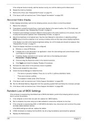
... Install Windows screen displays. e. The System Recovery Options screen displays. NOTE: Click Load Drivers if controller drives are set as the first boot device on page 255. h. Restart the computer and press F2 to correct the problem. 1. Run the Windows Disk Defragmenter. Run Windows Check Disk by entering chkdsk /r from a known good date using up-to-date software to resolve the problem. 4. Run a complete virus scan using System Restore. b. Select Repair your computer. Select the appropriate operating...
... Install Windows screen displays. e. The System Recovery Options screen displays. NOTE: Click Load Drivers if controller drives are set as the first boot device on page 255. h. Restart the computer and press F2 to correct the problem. 1. Run the Windows Disk Defragmenter. Run Windows Check Disk by entering chkdsk /r from a known good date using up-to-date software to resolve the problem. 4. Run a complete virus scan using System Restore. b. Select Repair your computer. Select the appropriate operating...

Service Guide
Page 166
... the following devices: • Non-Acer devices • Printer, mouse, and other external devices • Battery pack • Hard disk drive • DIMM • CD-ROM/Diskette drive Module • PC Cards 4. Remove or disconnect all attached devices are found, replace the FRU. 3. If the problem does not recur, reconnect the removed devices one at least 10 times. 2. If any problems are supported by a variety of the failure is operating correctly. (See "Power On...
... the following devices: • Non-Acer devices • Printer, mouse, and other external devices • Battery pack • Hard disk drive • DIMM • CD-ROM/Diskette drive Module • PC Cards 4. Remove or disconnect all attached devices are found, replace the FRU. 3. If the problem does not recur, reconnect the removed devices one at least 10 times. 2. If any problems are supported by a variety of the failure is operating correctly. (See "Power On...
Service Guide
Page 267
... BIOS Utility 23-31 Advanced 26 Boot 29 Exit 30 Navigating 23 Power 29 Save and Exit 30 Security 26 System Security 30 brightness hotkeys 13 C Camera Board Removing 91, 106 caps lock on indicator 9 Common Problems 146 CPU Replacing 112 CRT Cable Removing 80 D DIMM Module Removing 50 Display 5 display hotkeys 13 E Euro Key 14 External Module Disassembly Flowchart 42 Index F Features 1 FLASH Utility 31 Flash Utility 31 FRU (Field Replaceable Unit) List 167 H Hard Disk Drive Module Removing 48 Hibernation mode hotkey 13 Hot Keys 11 I Indicators 9 Intermittent Problems 156 Internal Microphone...
... BIOS Utility 23-31 Advanced 26 Boot 29 Exit 30 Navigating 23 Power 29 Save and Exit 30 Security 26 System Security 30 brightness hotkeys 13 C Camera Board Removing 91, 106 caps lock on indicator 9 Common Problems 146 CPU Replacing 112 CRT Cable Removing 80 D DIMM Module Removing 50 Display 5 display hotkeys 13 E Euro Key 14 External Module Disassembly Flowchart 42 Index F Features 1 FLASH Utility 31 Flash Utility 31 FRU (Field Replaceable Unit) List 167 H Hard Disk Drive Module Removing 48 Hibernation mode hotkey 13 Hot Keys 11 I Indicators 9 Intermittent Problems 156 Internal Microphone...


