Aspire 5750Z Battery - Acer
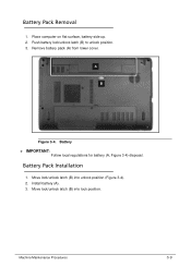
Aspire 5750Z Battery
Related Manual Pages


Similar Questions

Laptop Won't Charge
I just put in a new battery just hours ago, and my laptop said "find a power source" so I tried plug...
I just put in a new battery just hours ago, and my laptop said "find a power source" so I tried plug...
(Posted by anordmeyer1997 11 years ago)


Bios Battery
I tried hard to find the bios battery of my acer travelmate 4330 laptop bt I cant find it can u plz ...
I tried hard to find the bios battery of my acer travelmate 4330 laptop bt I cant find it can u plz ...
(Posted by zainzoni14 12 years ago)

Battery Doesn't Charge
What software in my computer allows my battery to charge? This is because I have been unable to char...
What software in my computer allows my battery to charge? This is because I have been unable to char...
(Posted by gaiusnti 12 years ago)
Related Terms
The following terms were also used when searching for Aspire 5750Z Battery - Acer:- acer aspire 5750
- acer aspire 5750 core i7
- acer aspire 5750 drivers
- acer aspire 5750 i7
- acer aspire 5750 manual
- acer aspire 5750 notebook
- acer aspire 5750 price
- acer aspire 5750 series
- acer aspire 5750 speaker
- acer aspire 5750 specs
- acer aspire 5750g
- acer aspire 5750g driver
- acer aspire 5750g drivers
- acer aspire 5750g i5
- acer aspire 5750z
- acer aspire 5750z 15.4 laptop
- acer aspire 5750z 15.4 laptop blue
- acer aspire 5750z 15.6 laptop blue
- acer aspire 5750z 15.6 notebook
- acer aspire 5750z 4477
- acer aspire 5750z 4830
- acer aspire 5750z 4835
- acer aspire 5750z 4835 manual
- acer aspire 5750z 4877
- acer aspire 5750z 4882
- acer aspire 5750z 4882 laptop
- acer aspire 5750z 4882 manual
- acer aspire 5750z 4882 replacement screen
- acer aspire 5750z base system device driver
- acer aspire 5750z battery
- acer aspire 5750z battery price
- acer aspire 5750z battery price in india
- acer aspire 5750z bluetooth
- acer aspire 5750z charger
- acer aspire 5750z configuration
- acer aspire 5750z cpu upgrade
- acer aspire 5750z dc power jack
- acer aspire 5750z dimensions
- acer aspire 5750z dimensions of hard drive
- acer aspire 5750z driver
- acer aspire 5750z drivers
- acer aspire 5750z drivers for windows 7
- acer aspire 5750z drivers for windows 7 32bit
- acer aspire 5750z drivers for windows 7 free
- acer aspire 5750z drivers for xp
- acer aspire 5750z ethernet driver
- acer aspire 5750z factory reset
- acer aspire 5750z factory restore
- acer aspire 5750z gaming
- acer aspire 5750z graphics card
- acer aspire 5750z hard drive
- acer aspire 5750z keyboard
- acer aspire 5750z keyboard cover
- acer aspire 5750z laptop
- acer aspire 5750z laptop price
- acer aspire 5750z laptop review
- acer aspire 5750z manual
- acer aspire 5750z memory upgrade
- acer aspire 5750z motherboard
- acer aspire 5750z network adapter driver
- acer aspire 5750z network controller
- acer aspire 5750z network drivers
- acer aspire 5750z nic drivers
- acer aspire 5750z notebook
- acer aspire 5750z parts
- acer aspire 5750z power button board
- acer aspire 5750z power cord
- acer aspire 5750z power supply
- acer aspire 5750z price
- acer aspire 5750z price in india
- acer aspire 5750z processor upgrade
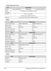
- acer aspire 5750z ram
- acer aspire 5750z ram crash problem
- acer aspire 5750z ram issue
- acer aspire 5750z ram upgrade
- acer aspire 5750z recovery
- acer aspire 5750z recovery disk
- acer aspire 5750z remove keyboard
- acer aspire 5750z review
- acer aspire 5750z reviews
- acer aspire 5750z service manual
- acer aspire 5750z sm bus driver
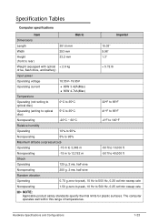
- acer aspire 5750z specification
- acer aspire 5750z specifications
- acer aspire 5750z specs
- acer aspire 5750z system restore
- acer aspire 5750z wallpaper
- acer aspire 5750z wifi problems
- acer aspire 5750z windows xp driver
- acer aspire 5750z wireless
- acer aspire 5750z wireless driver
- acer aspire 5750z wireless switch
- acer aspire 5750z xp driver
- acer aspire 5750z xp drivers
- acer aspire 5750z-4477
- acer aspire 5750z-4477 keyboard
- acer aspire 5750z-4830
- acer aspire 5750z-4830 battery
- acer aspire 5750z-4835
- acer aspire 5750z-4835 manual
- acer aspire 5750z-4835 new
- acer aspire 5750z-4835 screen replacement
- acer aspire 5750z-4877
- acer aspire 5750z-4879
- acer aspire 5750z-4882
- acer aspire 5750z-4882 battery
- acer aspire 5750z-4882 service manual
- acer aspire5750z
- aspire 5750
- aspire 5750 buy
- aspire 5750 core i7
- aspire 5750 core i7 made in
- aspire 5750 drivers
- aspire 5750 i7
- aspire 5750 manual
- aspire 5750 notebook
- aspire 5750 price
- aspire 5750 series
- aspire 5750 speaker
- aspire 5750 specifications
- aspire 5750 specs
- aspire 5750g
- aspire 5750g acer aspire 5750g
- aspire 5750g driver
- aspire 5750g drivers
- aspire 5750g i5
- aspire 5750z
- aspire 5750z (dos)
- aspire 5750z 15.4 laptop
- aspire 5750z 15.4 laptop blue
- aspire 5750z 15.6 laptop blue
- aspire 5750z 15.6 notebook
- aspire 5750z 4477
- aspire 5750z 4477 replacement screen
- aspire 5750z 4830
- aspire 5750z 4835
- aspire 5750z 4835 manual
- aspire 5750z 4877
- aspire 5750z 4882
- aspire 5750z 4882 laptop
- aspire 5750z 4882 manual
- aspire 5750z 4882 replacement screen
- aspire 5750z acer
- aspire 5750z base system device driver
- aspire 5750z battery
- aspire 5750z battery price
- aspire 5750z battery price in india
- aspire 5750z bluetooth
- aspire 5750z bluetooth driver
- aspire 5750z camera driver
- aspire 5750z charger
- aspire 5750z cpu upgrade
- aspire 5750z dc power jack
- aspire 5750z dimensions
- aspire 5750z dimensions of hard drive
- aspire 5750z driver
- aspire 5750z driver download
- aspire 5750z drivers
- aspire 5750z drivers for windows 7
- aspire 5750z drivers for windows 7 32bit
- aspire 5750z drivers for windows 7 free
- aspire 5750z drivers for xp
- aspire 5750z drivers windows 7
- aspire 5750z ethernet driver
- aspire 5750z factory reset
- aspire 5750z factory restore
- aspire 5750z free drivers
- aspire 5750z gaming
- aspire 5750z graphics card
- aspire 5750z hard drive
- aspire 5750z how to replace keyboard
- aspire 5750z keyboard
- aspire 5750z keyboard cover
- aspire 5750z laptop
- aspire 5750z laptop price
- aspire 5750z laptop review
- aspire 5750z manual
- aspire 5750z memory
- aspire 5750z motherboard
- aspire 5750z network adapter driver
- aspire 5750z network controller
- aspire 5750z network drivers
- aspire 5750z nic drivers
- aspire 5750z notebook
- aspire 5750z parts
- aspire 5750z power button board
- aspire 5750z power cord
- aspire 5750z power supply
- aspire 5750z price
- aspire 5750z price in india
- aspire 5750z processor upgrade
- aspire 5750z ram
- aspire 5750z ram crash problem
- aspire 5750z ram issue
- aspire 5750z ram upgrade
- aspire 5750z recovery
- aspire 5750z recovery disk
- aspire 5750z remove keyboard
- aspire 5750z review
- aspire 5750z reviews
- aspire 5750z service manual
- aspire 5750z setup disc
- aspire 5750z sm bus driver
- aspire 5750z specification
- aspire 5750z specifications
- aspire 5750z specs
- aspire 5750z system restore
- aspire 5750z wallpaper
- aspire 5750z webcam driver
- aspire 5750z wifi driver
- aspire 5750z wifi problems
- aspire 5750z windows xp driver
- aspire 5750z wireless
- aspire 5750z wireless driver
- aspire 5750z wireless switch
- aspire 5750z xp driver
- aspire 5750z xp drivers
- aspire 5750z-4477
- aspire 5750z-4477 keyboard
- aspire 5750z-4830
- aspire 5750z-4830 battery
- aspire 5750z-4835
- aspire 5750z-4835 manual
- aspire 5750z-4835 new
- aspire 5750z-4835 screen replacement
- aspire 5750z-4877
- aspire 5750z-4877 screen
- aspire 5750z-4879
- aspire 5750z-4882
- aspire 5750z-4882 battery
- aspire 5750z-4882 service manual