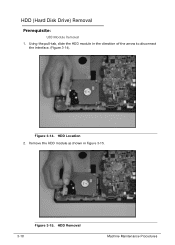
Aspire 5349, 5749, 5749Z Service Guide
Page 7
... UpperCase Screws and FFC Installation 3-12 ODD (Optical Disk Drive) Module Removal 3-13 ODD Module Installation 3-14 Base Cover Removal 3-15 Base Cover Installation 3-15 USB Module Removal 3-16 USB Module Installation 3-17 HDD (Hard Disk Drive) Removal 3-18 Hard Disk Drive Installation 3-19 RTC (Real Time Clock) Battery Removal 3-20 RTC Battery Installation 3-20 WLAN (Wireless Local Area Network...
Aspire 5349, 5749, 5749Z Service Guide
Page 86
... UpperCase Screws and FFC Installation 3-12 ODD (Optical Disk Drive) Module Removal 3-13 ODD Module Installation 3-14 Base Cover Removal 3-15 Base Cover Installation 3-15 USB Module Removal 3-16 USB Module Installation 3-17 HDD (Hard Disk Drive) Removal 3-18 Hard Disk Drive Installation 3-19 RTC (Real Time Clock) Battery Removal 3-20 RTC Battery Installation 3-20 WLAN (Wireless Local Area Network...
Aspire 5349, 5749, 5749Z Service Guide
Page 102
Using the pull-tab, slide the HDD module in Figure 3-15. 3-18 Figure 3-15. HDD Removal Machine Maintenance Procedures HDD Location 2. HDD (Hard Disk Drive) Removal 0 Prerequisite: USB Module Removal 1. Figure 3-14. Remove the HDD module as shown in the direction of the arrow to disconnect the interface. (Figure 3-14).
Aspire 5349, 5749, 5749Z Service Guide
Page 103
Remove HDD bracket (D) from HDD bracket (B) Figure 3-15. Hard Disk Drive Installation 0 1. Instal four (4) screws (C) and secure HDD brackets (D) to HDD module (Figure 3-16). 3. Install the USB module. Put HDD brackets ont HDD module (Figure 3-16). 2. ID Size C M3*3.5 Quantity 4 Screw Type Machine Maintenance Procedures 3-19 A A B A A Figure 3-16. Remove four (4) screws (A) from HDD module. Install the hard drive into the hard drive compartment. (Figure 3-15). 4. 3. HDD Module 4.
Aspire 5349, 5749, 5749Z Service Guide
Page 152
...;LCD assembly 4-16 Troubleshooting Remove power from the computer. 2. Remove or disconnect all attached devices are no error is inoperative. If the problem remains, replace the following devices: Non-Acer devices Printer, mouse, and other external devices Battery pack Hard disk drive DIMM ...