Quick Start Guide
Page 7
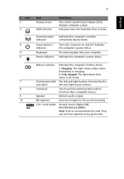
... and right mouse buttons. Only one card can operate at any given time. Touch-sensitive pointing device which functions like the left and right) Touchpad Speaker Microphone 2-in AC mode. Fully charged: The light shows blue when in -1 card reader Indicates the computer's battery status. 1. The left and right buttons function...
... and right mouse buttons. Only one card can operate at any given time. Touch-sensitive pointing device which functions like the left and right) Touchpad Speaker Microphone 2-in AC mode. Fully charged: The light shows blue when in -1 card reader Indicates the computer's battery status. 1. The left and right buttons function...
Quick Start Guide
Page 8
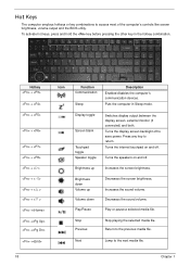
Speaker toggle Turns the speakers on and off. Stop playing the selected media file. Sleep Puts the computer in the hotkey combination. Increases the sound volume. + < > Volume down Volume up ...
Speaker toggle Turns the speakers on and off. Stop playing the selected media file. Sleep Puts the computer in the hotkey combination. Increases the sound volume. + < > Volume down Volume up ...
Quick Start Guide
Page 9
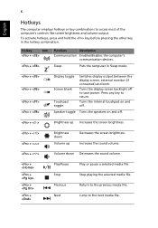
based network. 4 HDMI port Supports high-definition digital video connections. 5 USB 2.0 port Connect to audio line-out devices line-out jack (e.g., speakers, headphones). Headphone/speaker/ Connects to USB 2.0 devices (e.g., USB mouse, USB camera). 6 Microphone jack Accepts inputs from external microphones. English 7 Rear view # Item 1 Battery bay Left view 1 Description Houses ...
based network. 4 HDMI port Supports high-definition digital video connections. 5 USB 2.0 port Connect to audio line-out devices line-out jack (e.g., speakers, headphones). Headphone/speaker/ Connects to USB 2.0 devices (e.g., USB mouse, USB camera). 6 Microphone jack Accepts inputs from external microphones. English 7 Rear view # Item 1 Battery bay Left view 1 Description Houses ...
Service Guide
Page 7
... System Specifications 1 Features 1 System Block Diagram 6 UMA 6 Discrete (nVidia 7 Discrete (ATI 8 Your Acer Notebook tour 9 Top View 9 Rear view 10 Left View 11 Right View 12 Base view 13 Indicators ...Hot Keys 18 Hardware Specifications and Configurations 19 System Utilities 31 BIOS Setup Utility 31 Navigating the BIOS Utility 31 Aspire 5742/5742G/5742Z/5742ZG BIOS 32 Information 32 Main 33 Security 34 Boot 37 Exit 38 BIOS Flash Utilities 39 DOS... Process 66 Main Unit Disassembly Flowchart 66 Removing the Upper Cover 67 Removing the Speaker Module 72 VII
... System Specifications 1 Features 1 System Block Diagram 6 UMA 6 Discrete (nVidia 7 Discrete (ATI 8 Your Acer Notebook tour 9 Top View 9 Rear view 10 Left View 11 Right View 12 Base view 13 Indicators ...Hot Keys 18 Hardware Specifications and Configurations 19 System Utilities 31 BIOS Setup Utility 31 Navigating the BIOS Utility 31 Aspire 5742/5742G/5742Z/5742ZG BIOS 32 Information 32 Main 33 Security 34 Boot 37 Exit 38 BIOS Flash Utilities 39 DOS... Process 66 Main Unit Disassembly Flowchart 66 Removing the Upper Cover 67 Removing the Speaker Module 72 VII
Service Guide
Page 8
... Replacing the USB Board 135 Replacing the Card Reader Board (Discrete Only 137 Replacing the Touchpad FFC 139 Replacing the Power Board 140 Replacing the Speaker Module 141 Replacing the Upper Cover 142 Replacing the RTC Battery (UMA Only 146 Replacing the HDD Module 147 Replacing the WLAN Module 149 Replacing...
... Replacing the USB Board 135 Replacing the Card Reader Board (Discrete Only 137 Replacing the Touchpad FFC 139 Replacing the Power Board 140 Replacing the Speaker Module 141 Replacing the Upper Cover 142 Replacing the RTC Battery (UMA Only 146 Replacing the HDD Module 147 Replacing the WLAN Module 149 Replacing...
Service Guide
Page 9
...No Display Issue 161 Random Loss of BIOS Settings 162 LCD Failure 163 Internal Keyboard Failure 163 Touch Pad Failure 164 Internal Speaker Failure 164 Microphone Record Failure 166 USB Failure (Right side 167 HDD Not Operating Correctly 168 ODD Failure 169 Wireless Function... 197 FRU (Field Replaceable Unit) List 199 Aspire Exploded Diagrams 200 Main Assembly 200 Lower Cover 202 LCD Assembly 203 LED Assembly 204 Aspire FRU List 205 Screw List 229 Model Definition and Configuration 231 Aspire 5742/5742G 231 Aspire 5742Z/5742ZG 257 Test Compatible Components 273 Online...
...No Display Issue 161 Random Loss of BIOS Settings 162 LCD Failure 163 Internal Keyboard Failure 163 Touch Pad Failure 164 Internal Speaker Failure 164 Microphone Record Failure 166 USB Failure (Right side 167 HDD Not Operating Correctly 168 ODD Failure 169 Wireless Function... 197 FRU (Field Replaceable Unit) List 199 Aspire Exploded Diagrams 200 Main Assembly 200 Lower Cover 202 LCD Assembly 203 LED Assembly 204 Aspire FRU List 205 Screw List 229 Model Definition and Configuration 231 Aspire 5742/5742G 231 Aspire 5742Z/5742ZG 257 Test Compatible Components 273 Online...
Service Guide
Page 11
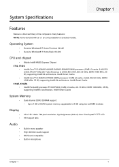
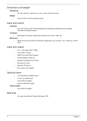
...® 7 Home Premium 64-bit2 • Genuine Windows® 7 Home Basic 64-bit2 CPU and chipset • Mobile Intel® HM55 Express Chipset 5742, 5742G • Intel® Core™ i5-450M/i5-460M/i5-540M/i5-560M/i5-580M processor (3 MB L3 cache, 2.40/2.53/ 2.53/2.67...DDR3 system memory, upgradable to 8 GB using two soDIMM modules Display • • 15.6" HD 1366 x 768 pixel resolution, high-brightness (200-nit) Acer CineCrystal™ TFT LCD 16:9 aspect ratio Audio Built-in mono speaker High-definition audio support MS-Sound compatible Built-in microphone Chapter 1 1
...® 7 Home Premium 64-bit2 • Genuine Windows® 7 Home Basic 64-bit2 CPU and chipset • Mobile Intel® HM55 Express Chipset 5742, 5742G • Intel® Core™ i5-450M/i5-460M/i5-540M/i5-560M/i5-580M processor (3 MB L3 cache, 2.40/2.53/ 2.53/2.67...DDR3 system memory, upgradable to 8 GB using two soDIMM modules Display • • 15.6" HD 1366 x 768 pixel resolution, high-brightness (200-nit) Acer CineCrystal™ TFT LCD 16:9 aspect ratio Audio Built-in mono speaker High-definition audio support MS-Sound compatible Built-in microphone Chapter 1 1
Service Guide
Page 14
...0.98/1.33 inches) Weight: • 2.6 kg (5.74 lbs.) with 6-cell battery pack Input and control Keyboard: • 103-/104-/107-key Acer FineTip keyboard with independent standard numeric keypad, international language support Touchpad: • Multi-gesture touchpad, supporting two-finger scroll, pinch, rotate, flip Media ...™, MMC) • Three USB 2.0 ports • HDMI™ port with HDCP support • External display (VGA) port • Headphone/speaker/line-out jack • Microphone-in jack • Ethernet (RJ-45) port • DC-in jack for AC adapter Optional items • ...
...0.98/1.33 inches) Weight: • 2.6 kg (5.74 lbs.) with 6-cell battery pack Input and control Keyboard: • 103-/104-/107-key Acer FineTip keyboard with independent standard numeric keypad, international language support Touchpad: • Multi-gesture touchpad, supporting two-finger scroll, pinch, rotate, flip Media ...™, MMC) • Three USB 2.0 ports • HDMI™ port with HDCP support • External display (VGA) port • Headphone/speaker/line-out jack • Microphone-in jack • Ethernet (RJ-45) port • DC-in jack for AC adapter Optional items • ...

Service Guide
Page 20
...: The 2-in1 card reader will be on the front left and right mouse buttons. 8 Touch pad Touch-sensitive pointing device which functions like a computer mouse. 9 Speaker Delivers audio output. 10 Microphone Internal microphone for discrete models. Fully charged: The light shows blue when in AC mode. 7 Click buttons (left The left...
...: The 2-in1 card reader will be on the front left and right mouse buttons. 8 Touch pad Touch-sensitive pointing device which functions like a computer mouse. 9 Speaker Delivers audio output. 10 Microphone Internal microphone for discrete models. Fully charged: The light shows blue when in AC mode. 7 Click buttons (left The left...

Service Guide
Page 21
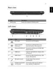
Connects to USB 2.0 devices (e.g., USB mouse, USB camera). USB 2.0 port Microphone jack Headphone/ speaker/ line-out jack Connect to an Ethernet 10/100/1000based network. Accepts inputs from external microphones. External display (VGA) port Ethernet (RJ-45) port HDMI port Connects to audio line-out devices (e.g., speakers, headphones). Chapter 1 11 Supports high-definition digital video connections. Connects to a display device (e.g., external monitor, LCD projector). Left View No. 1 2 3 4 5 6 1 Icon 2 34 56 Item DC-in jack Description Connects to an AC adapter.
Connects to USB 2.0 devices (e.g., USB mouse, USB camera). USB 2.0 port Microphone jack Headphone/ speaker/ line-out jack Connect to an Ethernet 10/100/1000based network. Accepts inputs from external microphones. External display (VGA) port Ethernet (RJ-45) port HDMI port Connects to audio line-out devices (e.g., speakers, headphones). Chapter 1 11 Supports high-definition digital video connections. Connects to a display device (e.g., external monitor, LCD projector). Left View No. 1 2 3 4 5 6 1 Icon 2 34 56 Item DC-in jack Description Connects to an AC adapter.
Service Guide
Page 28
Turns the speakers on and off. Increases the screen brightness. Decreases the sound volume. Hot Keys The computer employs hotkeys or key combinations to return. Press any key ... computer's controls like screen brightness, volume output and the BIOS utility. Return to the next media file. 18 Chapter 1 Display toggle Screen blank Touchpad toggle Speaker toggle Brightness up Brightness down Volume up Volume down Play/Pause Switches display output between the display screen, external monitor (if connected) and both. Turns...
Turns the speakers on and off. Increases the screen brightness. Decreases the sound volume. Hot Keys The computer employs hotkeys or key combinations to return. Press any key ... computer's controls like screen brightness, volume output and the BIOS utility. Return to the next media file. 18 Chapter 1 Display toggle Screen blank Touchpad toggle Speaker toggle Brightness up Brightness down Volume up Volume down Play/Pause Switches display output between the display screen, external monitor (if connected) and both. Turns...

Service Guide
Page 33
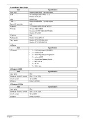
...ETB/SM08B-SURS-TF Audio Interface Item Audio Controller Audio onboard or optional Mono or Stereo Resolution Compatibility Sampling rate Internal microphone Internal speaker/quantity Specification Realtek ALC272X-GR Built-in Mono Support 16/24bit PCM HD audio Interface Sample rate up to 192Khz resolution VSR (...Variable Sampling Rate) Yes Yes/1 (2W speakers) LED 15.6" Item Vendor/model name Screen Diagonal (mm) Active Area (mm) Display resolution (pixels) Pixel Pitch (mm) Pixel Arrangement Display...
...ETB/SM08B-SURS-TF Audio Interface Item Audio Controller Audio onboard or optional Mono or Stereo Resolution Compatibility Sampling rate Internal microphone Internal speaker/quantity Specification Realtek ALC272X-GR Built-in Mono Support 16/24bit PCM HD audio Interface Sample rate up to 192Khz resolution VSR (...Variable Sampling Rate) Yes Yes/1 (2W speakers) LED 15.6" Item Vendor/model name Screen Diagonal (mm) Active Area (mm) Display resolution (pixels) Pixel Pitch (mm) Pixel Arrangement Display...
Service Guide
Page 37
...(DIS) I/O Ports Item I/O support Specification • 1 x 2 in1 card reader (SD/MMC) • 3 x USB 2.0 port • 1 x HDMI™ port supporting HDCP • 1 x external CRT • 1 x Headphone/speaker/lineout • 1 x MIC/Line in • 1 x RJ-45 • 1 x DC-in jack AC Adapter (UMA) Item Input rating Maximum input AC current Inrush current Efficiency...
...(DIS) I/O Ports Item I/O support Specification • 1 x 2 in1 card reader (SD/MMC) • 3 x USB 2.0 port • 1 x HDMI™ port supporting HDCP • 1 x external CRT • 1 x Headphone/speaker/lineout • 1 x MIC/Line in • 1 x RJ-45 • 1 x DC-in jack AC Adapter (UMA) Item Input rating Maximum input AC current Inrush current Efficiency...

Service Guide
Page 78
Turn the computer over and disconnect the power board FFC (A), microphone cable (B), speaker cable (C), and touch pad FFC (D) from the connector. 5. To release the power board FFC, release the locking latch and pull the cable from the mainboard. To release the microphone cable, pull out the cable from the connector. 68 Chapter 3 B C A D 4. 3.
Turn the computer over and disconnect the power board FFC (A), microphone cable (B), speaker cable (C), and touch pad FFC (D) from the connector. 5. To release the power board FFC, release the locking latch and pull the cable from the mainboard. To release the microphone cable, pull out the cable from the connector. 68 Chapter 3 B C A D 4. 3.

Service Guide
Page 79
NOTE: Use the pull-tabs on cables directly to prevent damage to prevent damage. 6. NOTE: Avoid pulling on FFCs where available to the connectors. To release the speaker cable, pull out the cable from the connector. To release the touch pad FFC, release the locking latch and pull the cable from the connector. 7. Chapter 3 69
NOTE: Use the pull-tabs on cables directly to prevent damage to prevent damage. 6. NOTE: Avoid pulling on FFCs where available to the connectors. To release the speaker cable, pull out the cable from the connector. To release the touch pad FFC, release the locking latch and pull the cable from the connector. 7. Chapter 3 69

Service Guide
Page 82
Locate the speaker module on page 67. 2. See "Removing the Upper Cover" on the upper cover as shown. 3. To remove the speaker, pull back on the rubber casing with a plastic tool (1) and lift the speaker module out using the thumb and forefinger (2). 2 1 NOTE: Do not grasp the underside of the speaker too tightly as shown. 4. Release the speaker cable from the guides as the speaker cover may get damaged. 72 Chapter 3 Removing the Speaker Module 1.
Locate the speaker module on page 67. 2. See "Removing the Upper Cover" on the upper cover as shown. 3. To remove the speaker, pull back on the rubber casing with a plastic tool (1) and lift the speaker module out using the thumb and forefinger (2). 2 1 NOTE: Do not grasp the underside of the speaker too tightly as shown. 4. Release the speaker cable from the guides as the speaker cover may get damaged. 72 Chapter 3 Removing the Speaker Module 1.

Service Guide
Page 83
Lift the speaker module clear of the device. Chapter 3 73 5.
Lift the speaker module clear of the device. Chapter 3 73 5.

Service Guide
Page 151
Replacing the Speaker Module 1. Chapter 3 141 Place the speaker module cable into the cable guides as shown. Place the speaker module onto the upper cover. 2.
Replacing the Speaker Module 1. Chapter 3 141 Place the speaker module cable into the cable guides as shown. Place the speaker module onto the upper cover. 2.

Service Guide
Page 153
2. To connect and lock the power board FFC (A) to the mainboard. Connect the power board FFC (A), microphone cable (B), speaker cable (C), and touch pad FFC (D) to the mainboard connector. 4. Chapter 3 143 B C A D 3. Connect the microphone cable to the mainboard connector.
2. To connect and lock the power board FFC (A) to the mainboard. Connect the power board FFC (A), microphone cable (B), speaker cable (C), and touch pad FFC (D) to the mainboard connector. 4. Chapter 3 143 B C A D 3. Connect the microphone cable to the mainboard connector.

Service Guide
Page 154
5. Connect the speaker cable to the mainboard connector. 144 Chapter 3 Connect and lock the touch pad FFC to the mainboard connector. 6.
5. Connect the speaker cable to the mainboard connector. 144 Chapter 3 Connect and lock the touch pad FFC to the mainboard connector. 6.


