Aspire 5320/5715/5715Z/5720/5720G User's Guide EN
Page 4
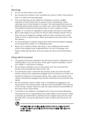
... operation of the power strip's input rating. Also, make sure that could be placed near water. The overall system load must not be blocked or covered. Contact your dealer or local power company. iv Warnings • • • Do not use it under sporting, exercising, or any vibrating environment which will...
... operation of the power strip's input rating. Also, make sure that could be placed near water. The overall system load must not be blocked or covered. Contact your dealer or local power company. iv Warnings • • • Do not use it under sporting, exercising, or any vibrating environment which will...
Aspire 5320/5715/5715Z/5720/5720G User's Guide EN
Page 5
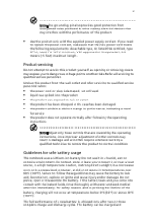
... not use it to temperatures over 60°C (140°F). Unplug this product from unexpected noise produced by other nearby electrical devices that are covered by a qualified technician to restore the product to normal condition. Do not put, store or leave your product in or near a heat source...the operating instructions, since improper adjustment of other risks. Product servicing Do not attempt to service this product yourself, as opening or removing covers may cause the battery to leak acid, become hot, explode or ignite and cause injury and/or damage. Failure to follow these ...
... not use it to temperatures over 60°C (140°F). Unplug this product from unexpected noise produced by other nearby electrical devices that are covered by a qualified technician to restore the product to normal condition. Do not put, store or leave your product in or near a heat source...the operating instructions, since improper adjustment of other risks. Product servicing Do not attempt to service this product yourself, as opening or removing covers may cause the battery to leak acid, become hot, explode or ignite and cause injury and/or damage. Failure to follow these ...

Aspire 5320/5715/5715Z/5720/5720G User's Guide EN
Page 40
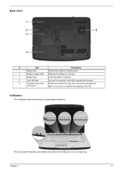
20 English Base view 1 2 3 4 5 6 # 1 Icon Item Battery bay Description Houses the computer's battery pack. 2 Battery release latch Releases the battery for removal. 3 Battery lock Locks the battery in position. 4 5 6 Memory compartment Hard disk bay Ventilation slots and cooling fan Houses the computer's main memory. Enable the computer to stay cool, even after prolonged use. Note: Do not cover or obstruct the opening of the fan. Houses the computer's hard disk (secured with screws).
20 English Base view 1 2 3 4 5 6 # 1 Icon Item Battery bay Description Houses the computer's battery pack. 2 Battery release latch Releases the battery for removal. 3 Battery lock Locks the battery in position. 4 5 6 Memory compartment Hard disk bay Ventilation slots and cooling fan Houses the computer's main memory. Enable the computer to stay cool, even after prolonged use. Note: Do not cover or obstruct the opening of the fan. Houses the computer's hard disk (secured with screws).

Aspire 5320/5715/5715Z/5720/5720G User's Guide EN
Page 45
Indicates when the hard disk drive is closed up. Lights up when Num Lock is activated. Fully charged: The light shows green when in AC mode. Indicates the computer's batttery status. Icon Function Power Battery HDD Num Lock Caps Lock Description Indicates the computer's power status. Lights up when Caps Lock is charging. 2. English The front panel indicators are visible even when the computer cover is active. 25 Indicators The computer has serveral easy-to-read status indicators. Charging: The light shows amber when the battery is activated. 1.
Indicates when the hard disk drive is closed up. Lights up when Num Lock is activated. Fully charged: The light shows green when in AC mode. Indicates the computer's batttery status. Icon Function Power Battery HDD Num Lock Caps Lock Description Indicates the computer's power status. Lights up when Caps Lock is charging. 2. English The front panel indicators are visible even when the computer cover is active. 25 Indicators The computer has serveral easy-to-read status indicators. Charging: The light shows amber when the battery is activated. 1.
Aspire 5320/5715/5715Z/5720/5720G User's Guide EN
Page 63
... your support, we can still get in contact with your proof-of-purchase in the flap located inside the front cover of time a call . Please consult http://global.acer.com. An ITW passport comes with our offices worldwide. Read this handy booklet. Always have the following information: Name... about the ITW program. 43 Requesting service International Travelers Warranty (ITW) Your computer is in this passport thoroughly. English Before you call Acer for online service, and please be at your ITW passport on the screen (or the number and sequence in the case of service ...
... your support, we can still get in contact with your proof-of-purchase in the flap located inside the front cover of time a call . Please consult http://global.acer.com. An ITW passport comes with our offices worldwide. Read this handy booklet. Always have the following information: Name... about the ITW program. 43 Requesting service International Travelers Warranty (ITW) Your computer is in this passport thoroughly. English Before you call Acer for online service, and please be at your ITW passport on the screen (or the number and sequence in the case of service ...
Aspire 5320/5715/5715Z/5720/5720G User's Guide EN
Page 85
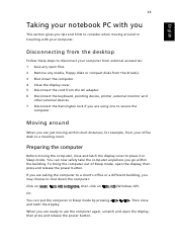
...are using one to shut down the computer. To bring the computer out of Sleep mode, open the display; Then close and latch the display cover to place it in Sleep mode by pressing + . Disconnect the keyboard, pointing device, printer, external monitor and other external devices. Preparing the... button. Shut down the computer: Click on Start, Turn Off Computer, then click on Turn Off (Windows XP). Close the display cover. Moving around or traveling with your computer. Or: You can now safely take the computer anywhere you may choose to secure the computer.
...are using one to shut down the computer. To bring the computer out of Sleep mode, open the display; Then close and latch the display cover to place it in Sleep mode by pressing + . Disconnect the keyboard, pointing device, printer, external monitor and other external devices. Preparing the... button. Shut down the computer: Click on Start, Turn Off Computer, then click on Turn Off (Windows XP). Close the display cover. Moving around or traveling with your computer. Or: You can now safely take the computer anywhere you may choose to secure the computer.
Aspire 5320/5715/5715Z/5720/5720G User's Guide EN
Page 86
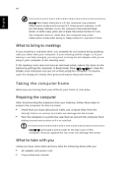
... release the power button to plug in your computer. If your office to remove the media can damage the screen. Press + or close the display cover whenever you : • • AC adapter and power cord The printed User's Guide If the meeting room. Preparing the computer After disconnecting the ... Taking the computer home When you are moving from your home or vice versa. Pack the computer in Sleep mode. Pressure against the top cover can damage the drive head. Note that the computer may want to bring anything with you to turn the computer back on. Failure to ...
... release the power button to plug in your computer. If your office to remove the media can damage the screen. Press + or close the display cover whenever you : • • AC adapter and power cord The printed User's Guide If the meeting room. Preparing the computer After disconnecting the ... Taking the computer home When you are moving from your home or vice versa. Pack the computer in Sleep mode. Pressure against the top cover can damage the drive head. Note that the computer may want to bring anything with you to turn the computer back on. Failure to ...

Aspire 5320/5715/5715Z/5720/5720G User's Guide EN
Page 95
...and remove the battery pack. then lift up and remove the memory cover. (a) Insert the memory module diagonally into place. Turn on the computer. Please consult a qualified technician or contact your local Acer dealer. 75 Installing memory Follow these steps to access its base. ...Remove the screws from the memory cover; The computer automatically detects and reconfigures the total memory size. Reinstall the battery...
...and remove the battery pack. then lift up and remove the memory cover. (a) Insert the memory module diagonally into place. Turn on the computer. Please consult a qualified technician or contact your local Acer dealer. 75 Installing memory Follow these steps to access its base. ...Remove the screws from the memory cover; The computer automatically detects and reconfigures the total memory size. Reinstall the battery...
Aspire 5320/5715/5715Z/5720/5720G/5720Z Service Guide
Page 5
... service of customer machines. You MUST use the list provided by your regional Acer office to extend the functionality of a machine (e.g. add-on your Acer office may have decided to order FRU parts for Acer's "global" product offering. If, for whatever reason, a part number change... is made, it supports, please read the following general information. 1. For ACER-AUTHORIZED SERVICE PROVIDERS, your regional web or channel. These LOCALIZED FEATURES will not be covered in this printed Service Guide. In such cases, please contact your regional office MAY have a ...
... service of customer machines. You MUST use the list provided by your regional Acer office to extend the functionality of a machine (e.g. add-on your Acer office may have decided to order FRU parts for Acer's "global" product offering. If, for whatever reason, a part number change... is made, it supports, please read the following general information. 1. For ACER-AUTHORIZED SERVICE PROVIDERS, your regional web or channel. These LOCALIZED FEATURES will not be covered in this printed Service Guide. In such cases, please contact your regional office MAY have a ...
Aspire 5320/5715/5715Z/5720/5720G/5720Z Service Guide
Page 17
...) 5 Ventilation slots and Enable the computer to -read status indicators. Chapter 1 11 The front panel indicators are visible even when the computer cover is closed up. cooling fan Note: Do not cover or obstruct the opening of the fan. Indicators The computer has several easy-to stay cool, even after prolonged use.
...) 5 Ventilation slots and Enable the computer to -read status indicators. Chapter 1 11 The front panel indicators are visible even when the computer cover is closed up. cooling fan Note: Do not cover or obstruct the opening of the fan. Indicators The computer has several easy-to stay cool, even after prolonged use.

Aspire 5320/5715/5715Z/5720/5720G/5720Z Service Guide
Page 59
To disassemble the computer, you remove the stripe cover, please be careful not to disassemble the notebook computer for the different components vary in size. When you need the following tools: T Wrist grounding strap ...: The screws for maintenance and troubleshooting. Chapter 3 53 Chapter 3 Machine Disassembly and Replacement This chapter contains step-by-step procedures on how to scrape the cover. During the disassembly process, group the screws with the corresponding components to avoid mismatch when putting back the components.
To disassemble the computer, you remove the stripe cover, please be careful not to disassemble the notebook computer for the different components vary in size. When you need the following tools: T Wrist grounding strap ...: The screws for maintenance and troubleshooting. Chapter 3 53 Chapter 3 Machine Disassembly and Replacement This chapter contains step-by-step procedures on how to scrape the cover. During the disassembly process, group the screws with the corresponding components to avoid mismatch when putting back the components.

Aspire 5320/5715/5715Z/5720/5720G/5720Z Service Guide
Page 61
Start Battery Pack B*1 D*1 System Fan B*4 Thermal Module F*1 ODD Module CPU D*5 F*1 Thermal Door Memory Lower Case Assembly F*1 Mimi Cover F*2 HDD Door H*4 HDD Bracket HDD Middle Cover F*2 Keyboard C*2 LCD hinges to logic D*2 LCD hinges to logic C*2 on bottom side LCD Module C*8 upper case assembly to lower case assembly on bottom side C*2 upper ...
Start Battery Pack B*1 D*1 System Fan B*4 Thermal Module F*1 ODD Module CPU D*5 F*1 Thermal Door Memory Lower Case Assembly F*1 Mimi Cover F*2 HDD Door H*4 HDD Bracket HDD Middle Cover F*2 Keyboard C*2 LCD hinges to logic D*2 LCD hinges to logic C*2 on bottom side LCD Module C*8 upper case assembly to lower case assembly on bottom side C*2 upper ...
Aspire 5320/5715/5715Z/5720/5720G/5720Z Service Guide
Page 64
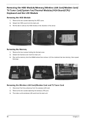
Remove the two screws fastening the HDD cover. 2. Removing the Memory 1. Detach the thermal cover from the wireless LAN card. 2. Disconnect the three antennae from the main unit. 3. Then take out the wireless LAN card from the DIMM socket then ... Wireless LAN Card/Modem Card and TV Tuner Card 1. Remove the two screws fastening the wireless LAN card. 3. Remove the four screws holding the thermal cover. 2. Detach the HDD cover from the main unit. 3. Pull the tab to remove the HDD module in the direction of the arrow.
Remove the two screws fastening the HDD cover. 2. Removing the Memory 1. Detach the thermal cover from the wireless LAN card. 2. Disconnect the three antennae from the main unit. 3. Then take out the wireless LAN card from the DIMM socket then ... Wireless LAN Card/Modem Card and TV Tuner Card 1. Remove the two screws fastening the wireless LAN card. 3. Remove the four screws holding the thermal cover. 2. Detach the HDD cover from the main unit. 3. Pull the tab to remove the HDD module in the direction of the arrow.

Aspire 5320/5715/5715Z/5720/5720G/5720Z Service Guide
Page 67
Turn the notebook over the keyboard as shown. 9. Remove the two screws securing the strip cover from the main board. 8. Gently pull up the keyboard to release it . 4. Turn over . 2. Pull out the wireless LAN antennas free from the four snaps ... LCD cable and microphone cable from the bottom of the notebook. 3. Chapter 3 61 Then disconnect the keyboard cable from the main unit. 7. Detach the strip cover from the front side and remove it from the main unit as the image shows. Remove the keyboard from the main board. 6. Removing the Keyboard...
Turn the notebook over the keyboard as shown. 9. Remove the two screws securing the strip cover from the main board. 8. Gently pull up the keyboard to release it . 4. Turn over . 2. Pull out the wireless LAN antennas free from the four snaps ... LCD cable and microphone cable from the bottom of the notebook. 3. Chapter 3 61 Then disconnect the keyboard cable from the main unit. 7. Detach the strip cover from the front side and remove it from the main unit as the image shows. Remove the keyboard from the main board. 6. Removing the Keyboard...
Aspire 5320/5715/5715Z/5720/5720G/5720Z Service Guide
Page 91
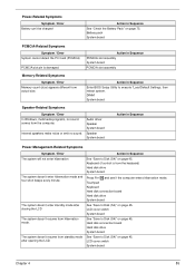
The system doesn't resume from actual size. LCD cover switch System board See "Save to execute "Load Default Settings, then reboot system. DIMM System board Speaker-Related Symptoms Symptom / Error In Windows, multimedia programs, ... the LCD The system doesn't resume from the keyboard) Hard disk drive System board Press Fn+oand see if the computer enters hibernation mode. LCD cover switch System board Chapter 4 85 Action in Sequence Enter BIOS Setup Utility to Disk (S4)" on page 45. Audio driver Speaker System board Speaker System...
The system doesn't resume from actual size. LCD cover switch System board See "Save to execute "Load Default Settings, then reboot system. DIMM System board Speaker-Related Symptoms Symptom / Error In Windows, multimedia programs, ... the LCD The system doesn't resume from the keyboard) Hard disk drive System board Press Fn+oand see if the computer enters hibernation mode. LCD cover switch System board Chapter 4 85 Action in Sequence Enter BIOS Setup Utility to Disk (S4)" on page 45. Audio driver Speaker System board Speaker System...
Aspire 5320/5715/5715Z/5720/5720G/5720Z Service Guide
Page 100
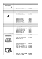
... W/O TV-15.4 60.AHE02.006 THERMAL DOOR 15.4 UMA 42.AHE02.002 94 Chapter 6 Part Name and Description RF CABLE 15.4 Acer Part No. 50.AHE02.005 7 PIN MINI-DIN S-VIDEO TO 4 CABLE PAL TO NTSC CONNECTOR SMB JACK DVB-T ANT DC-IN ...CABLE (90W) UMA/DIS 50.ABD02.001 20.ABD02.001 50.ABD02.002 50.ABD02.003 50.AHE02.009 50.AHH02.001 CASE/COVER/BRACKET ASSEMBLY POWER CORD US 3 PIN POWER CORD EU 3 PIN POWER CORD AUS 3 PIN POWER CORD UK 3 PIN POWER CORD...009 27.TAVV5.010 27.TAVV5.011 27.TAVV5.012 27.TAVV5.013 27.TAVV5.014 MIDDLE COVER 15.4 42.AHE02.001 UPPER CASE ASSY 15.4 W/TP TP BRACKET TP FFC -
... W/O TV-15.4 60.AHE02.006 THERMAL DOOR 15.4 UMA 42.AHE02.002 94 Chapter 6 Part Name and Description RF CABLE 15.4 Acer Part No. 50.AHE02.005 7 PIN MINI-DIN S-VIDEO TO 4 CABLE PAL TO NTSC CONNECTOR SMB JACK DVB-T ANT DC-IN ...CABLE (90W) UMA/DIS 50.ABD02.001 20.ABD02.001 50.ABD02.002 50.ABD02.003 50.AHE02.009 50.AHH02.001 CASE/COVER/BRACKET ASSEMBLY POWER CORD US 3 PIN POWER CORD EU 3 PIN POWER CORD AUS 3 PIN POWER CORD UK 3 PIN POWER CORD...009 27.TAVV5.010 27.TAVV5.011 27.TAVV5.012 27.TAVV5.013 27.TAVV5.014 MIDDLE COVER 15.4 42.AHE02.001 UPPER CASE ASSY 15.4 W/TP TP BRACKET TP FFC -


