Aspire 5349, 5749, 5749Z Service Guide
Page 7
... MAC EEPROM Utility 2-27 Crisis Disk Recovery 2-28 CHAPTER 3 Machine Maintenance Procedures Introduction 3-5 General Information 3-5 Recommended Equipment 3-5 Maintenance Flowchart 3-6 Getting Started 3-7 Battery Pack Removal 3-8 Battery Pack Installation 3-8 Dummy Card Removal 3-9 Dummy Card Installation 3-9 Keyboard Removal 3-10 Keyboard Installation 3-11 UpperCase Screws and FFC Removal 3-12 UpperCase Screws and FFC Installation 3-12 ODD (Optical Disk Drive) Module...
... MAC EEPROM Utility 2-27 Crisis Disk Recovery 2-28 CHAPTER 3 Machine Maintenance Procedures Introduction 3-5 General Information 3-5 Recommended Equipment 3-5 Maintenance Flowchart 3-6 Getting Started 3-7 Battery Pack Removal 3-8 Battery Pack Installation 3-8 Dummy Card Removal 3-9 Dummy Card Installation 3-9 Keyboard Removal 3-10 Keyboard Installation 3-11 UpperCase Screws and FFC Removal 3-12 UpperCase Screws and FFC Installation 3-12 ODD (Optical Disk Drive) Module...
Aspire 5349, 5749, 5749Z Service Guide
Page 8
... LCD Bezel Installation 3-45 Camera Module Removal 3-46 Camera Module Installation 3-47 LCD Panel Removal 3-48 LCD Panel Installation 3-49 LCD Hinge Removal 3-50 LCD Hinge Installation 3-50 LVDS Cable Removal 3-51 LVDS Cable Installation 3-52 CHAPTER 4 Troubleshooting Introduction 4-3 General Information 4-3 Power On Issues 4-4 No Display Issues 4-5 LCD Failure 4-8 Keyboard Failure 4-9 Touchpad Failure 4-10 Internal...
... LCD Bezel Installation 3-45 Camera Module Removal 3-46 Camera Module Installation 3-47 LCD Panel Removal 3-48 LCD Panel Installation 3-49 LCD Hinge Removal 3-50 LCD Hinge Installation 3-50 LVDS Cable Removal 3-51 LVDS Cable Installation 3-52 CHAPTER 4 Troubleshooting Introduction 4-3 General Information 4-3 Power On Issues 4-4 No Display Issues 4-5 LCD Failure 4-8 Keyboard Failure 4-9 Touchpad Failure 4-10 Internal...
Aspire 5349, 5749, 5749Z Service Guide
Page 86
... Information 3-5 Recommended Equipment 3-5 Maintenance Flowchart 3-6 Getting Started 3-7 Battery Pack Removal 3-8 Battery Pack Installation 3-8 Dummy Card Removal 3-9 Dummy Card Installation 3-9 Keyboard Removal 3-10 Keyboard Installation 3-11 UpperCase Screws and FFC Removal 3-12 UpperCase Screws and FFC Installation 3-12 ODD (Optical Disk Drive) Module Removal 3-13 ODD Module Installation 3-14 Base Cover Removal 3-15 Base Cover Installation 3-15 USB Module...
... Information 3-5 Recommended Equipment 3-5 Maintenance Flowchart 3-6 Getting Started 3-7 Battery Pack Removal 3-8 Battery Pack Installation 3-8 Dummy Card Removal 3-9 Dummy Card Installation 3-9 Keyboard Removal 3-10 Keyboard Installation 3-11 UpperCase Screws and FFC Removal 3-12 UpperCase Screws and FFC Installation 3-12 ODD (Optical Disk Drive) Module Removal 3-13 ODD Module Installation 3-14 Base Cover Removal 3-15 Base Cover Installation 3-15 USB Module...
Aspire 5349, 5749, 5749Z Service Guide
Page 90
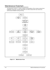
... 0 The flowchart in Jack LCD module Speaker LCD bezel Camera LCD panel LCD hinge LVDS cable Thermal module Figure 3-1. Battery Dummy card Keyboard Speaker cable Power FFC Touchpad FFC ODD module Base cover USB module HDD module WLAN module Bluetooth module Mainboard CPU PCH Lower case DIMM ...module Power board DC-in Figure 3-1 shows a graphic representation of the module removal and installation sequences. It shows information on what components may need to be removed and installed during servicing.
... 0 The flowchart in Jack LCD module Speaker LCD bezel Camera LCD panel LCD hinge LVDS cable Thermal module Figure 3-1. Battery Dummy card Keyboard Speaker cable Power FFC Touchpad FFC ODD module Base cover USB module HDD module WLAN module Bluetooth module Mainboard CPU PCH Lower case DIMM ...module Power board DC-in Figure 3-1 shows a graphic representation of the module removal and installation sequences. It shows information on what components may need to be removed and installed during servicing.
Aspire 5349, 5749, 5749Z Service Guide
Page 94
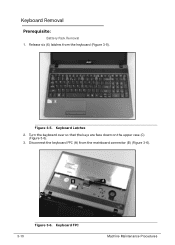
Keyboard Removal 0 Prerequisite: Battery Pack Removal 1. Disconnect the keyboard FPC (A) from the keyboard (Figure 3-5). Figure 3-5. B A C 3-10 Figure 3-6. Release six (6) latches from the mainboard connector (B) (Figure 3-6). Turn the keyboard over so that the keys are face down on the upper case (C) (Figure 3-6). 3. Keyboard FPC Machine Maintenance Procedures Keyboard Latches 2.
Keyboard Removal 0 Prerequisite: Battery Pack Removal 1. Disconnect the keyboard FPC (A) from the keyboard (Figure 3-5). Figure 3-5. B A C 3-10 Figure 3-6. Release six (6) latches from the mainboard connector (B) (Figure 3-6). Turn the keyboard over so that the keys are face down on the upper case (C) (Figure 3-6). 3. Keyboard FPC Machine Maintenance Procedures Keyboard Latches 2.
Aspire 5349, 5749, 5749Z Service Guide
Page 95
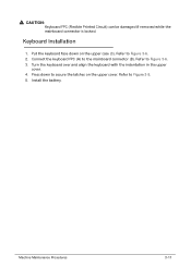
! Refer to Figure 3-5. 5. Refer to Figure 3-6. 2. Press down on the upper cover. Turn the keyboard over and align the keyboard with the indentation in the upper cover. 4. Machine Maintenance Procedures 3-11 Put the keyboard face down to secure the latches on the upper case (C). CAUTION: Keyboard FPC (Flexible Printed Circuit) can be damaged if removed while the mainboard connector is locked. Refer to the mainboard connector (B). Install the battery. Keyboard Installation 0 1. Connect the keyboard FPC (A) to Figure 3-6. 3.
! Refer to Figure 3-5. 5. Refer to Figure 3-6. 2. Press down on the upper cover. Turn the keyboard over and align the keyboard with the indentation in the upper cover. 4. Machine Maintenance Procedures 3-11 Put the keyboard face down to secure the latches on the upper case (C). CAUTION: Keyboard FPC (Flexible Printed Circuit) can be damaged if removed while the mainboard connector is locked. Refer to the mainboard connector (B). Install the battery. Keyboard Installation 0 1. Connect the keyboard FPC (A) to Figure 3-6. 3.
Aspire 5349, 5749, 5749Z Service Guide
Page 96
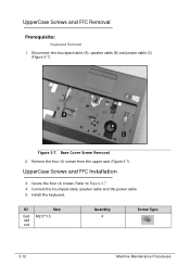
Remove the four (4) screws from the upper case (Figure 3-7). Secure the four (4) screws. Connect the touchpad cable, speaker cable and the power cable. 5. Base Cover Screw Removal 2. Install the keyboard. UpperCase Screws and FFC Removal 0 Prerequisite: Keyboard Removal 1. UpperCase Screws and FFC Installation 0 3. Refer to Figure 3-7. 4. A B C Figure 3-7. ID Size Red M2.5*3.5 Call out Quantity 4 Screw Type 3-12 Machine Maintenance Procedures Disconnect the touchpad cable (A), speaker cable (B) and power cable (C) (Figure 3-7).
Remove the four (4) screws from the upper case (Figure 3-7). Secure the four (4) screws. Connect the touchpad cable, speaker cable and the power cable. 5. Base Cover Screw Removal 2. Install the keyboard. UpperCase Screws and FFC Removal 0 Prerequisite: Keyboard Removal 1. UpperCase Screws and FFC Installation 0 3. Refer to Figure 3-7. 4. A B C Figure 3-7. ID Size Red M2.5*3.5 Call out Quantity 4 Screw Type 3-12 Machine Maintenance Procedures Disconnect the touchpad cable (A), speaker cable (B) and power cable (C) (Figure 3-7).


