Aspire 3000 / 3500 / 5000 Service Guide
Page 7
Table of Contents Chapter 1 System Introduction 1 Features 1 System Block Diagram (For Aspire 3000/5000 3 System Block Diagram (For Aspire 3500 4 Board Layout (For Aspire 3000/5000 5 Top View 5 Bottom View 6 Panel 8 Front view 8 Closed front view 9 Left view 9 Right view 10 Rear view...Drive Module 50 Disassembling the Hard Disc Drive Module 50 Removing the Optical Disc Drive Module 51 Disassembling the Optical Disc Drive Module 51 Removing the Memory 51 Removing the LCD Module 53 Removing the Middle Cover 53 Removing the Keyboard 53 Removing the Fan, the CPU Thermal Module ...
Table of Contents Chapter 1 System Introduction 1 Features 1 System Block Diagram (For Aspire 3000/5000 3 System Block Diagram (For Aspire 3500 4 Board Layout (For Aspire 3000/5000 5 Top View 5 Bottom View 6 Panel 8 Front view 8 Closed front view 9 Left view 9 Right view 10 Rear view...Drive Module 50 Disassembling the Hard Disc Drive Module 50 Removing the Optical Disc Drive Module 51 Disassembling the Optical Disc Drive Module 51 Removing the Memory 51 Removing the LCD Module 53 Removing the Middle Cover 53 Removing the Keyboard 53 Removing the Fan, the CPU Thermal Module ...
Aspire 3000 / 3500 / 5000 Service Guide
Page 8
.... .59 Removing the Speaker Set 60 Removing the SW DJ Board Assembly 60 Removing the Audio Board 61 Removing the VGA Thermal Module 61 Removing the Modem Board 62 Removing the Main Board 62 Removing the Control Board 63 Chapter 4 Troubleshooting 66 System Check ... Jumper and Connector Locations 84 Top View 84 Bottom View 86 Cahpter 6 FRU (Field Replaceable Unit) List 88 Aspire 3000/5000 Exploded Diagram 89 Aspire 3000/3500/5000 Series 101 Appendix A Model Definition and Configuration 101 Appendix B Test Compatible Components 104 Microsoft Windows XP Environment Test...
.... .59 Removing the Speaker Set 60 Removing the SW DJ Board Assembly 60 Removing the Audio Board 61 Removing the VGA Thermal Module 61 Removing the Modem Board 62 Removing the Main Board 62 Removing the Control Board 63 Chapter 4 Troubleshooting 66 System Check ... Jumper and Connector Locations 84 Top View 84 Bottom View 86 Cahpter 6 FRU (Field Replaceable Unit) List 88 Aspire 3000/5000 Exploded Diagram 89 Aspire 3000/3500/5000 Series 101 Appendix A Model Definition and Configuration 101 Appendix B Test Compatible Components 104 Microsoft Windows XP Environment Test...

Aspire 3000 / 3500 / 5000 Service Guide
Page 57
... *1 Modem Cover *2 Modem Board Hinge Caps *2 Middle Cover Keyboard *6 LCD Module *2 Launch Board Lower Case Assembly *2 FDD Module *3 *3 *11 *4 RTC Battery *3 Mini PCI Card Plate Upper Case Assembly Disconnect Wireless LAN Antenna *4 Thermal Module *4 Wireless LAN Antenna Touchpad Cover Wireless LAN Card CPU ODD Module *4 HDD Bracket *1 ODD Support Bracket *1 CPU Heatsink Plate *3 VGA Heatsink...
... *1 Modem Cover *2 Modem Board Hinge Caps *2 Middle Cover Keyboard *6 LCD Module *2 Launch Board Lower Case Assembly *2 FDD Module *3 *3 *11 *4 RTC Battery *3 Mini PCI Card Plate Upper Case Assembly Disconnect Wireless LAN Antenna *4 Thermal Module *4 Wireless LAN Antenna Touchpad Cover Wireless LAN Card CPU ODD Module *4 HDD Bracket *1 ODD Support Bracket *1 CPU Heatsink Plate *3 VGA Heatsink...

Aspire 3000 / 3500 / 5000 Service Guide
Page 62
... the Middle Cover 1. See "Removing the Keyboard" on page 53. 3. Disconnect the keyboard cable then remove the keyboard. Removing the Fan, the CPU Thermal Module and the CPU 1. Removing the Keyboard 1. See "Removing the Middle Cover" on page 53. 4. Detach the middle cover carefully then remove it. See "Removing the ...
... the Middle Cover 1. See "Removing the Keyboard" on page 53. 3. Disconnect the keyboard cable then remove the keyboard. Removing the Fan, the CPU Thermal Module and the CPU 1. Removing the Keyboard 1. See "Removing the Middle Cover" on page 53. 4. Detach the middle cover carefully then remove it. See "Removing the ...
Aspire 3000 / 3500 / 5000 Service Guide
Page 63
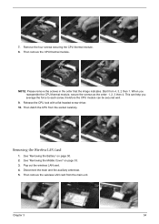
...page 50. 2. Removing the Wireless LAN Card 1. Pop out the wireless LAN card. 4. Chapter 3 54 7. Remove the four screws securing the CPU thermal module. 8. Start from the socket carefully. NOTE: Please remove the screws in the order that the image indicates. Release the CPU lock with a flat headed ...screw driver. 10. This can help you reassemble the CPU thermal module, secure the screws as the order: 1, 2, 3 then 4. See "Removing the Battery" on page 53. 3. Then remove the wireless LAN card ...
...page 50. 2. Removing the Wireless LAN Card 1. Pop out the wireless LAN card. 4. Chapter 3 54 7. Remove the four screws securing the CPU thermal module. 8. Start from the socket carefully. NOTE: Please remove the screws in the order that the image indicates. Release the CPU lock with a flat headed ...screw driver. 10. This can help you reassemble the CPU thermal module, secure the screws as the order: 1, 2, 3 then 4. See "Removing the Battery" on page 53. 3. Then remove the wireless LAN card ...

Aspire 3000 / 3500 / 5000 Service Guide
Page 65
... four screws securing the left LCD bracket, then remove the left bracket. See "Removing the LCD Module" on page 53. 5. Chapter 3 56 Disassembling the LCD Module Removing the LCD Bezel 1. See "Removing the Fan, the CPU Thermal Module and the CPU" on page 55. 7. Turn over the LCD. 15. See "Removing the Keyboard" on...
... four screws securing the left LCD bracket, then remove the left bracket. See "Removing the LCD Module" on page 53. 5. Chapter 3 56 Disassembling the LCD Module Removing the LCD Bezel 1. See "Removing the Fan, the CPU Thermal Module and the CPU" on page 55. 7. Turn over the LCD. 15. See "Removing the Keyboard" on...

Aspire 3000 / 3500 / 5000 Service Guide
Page 70
... DJ board and SW DJ board bracket. 10. See "Removing the Power Board" on page 53. 4. Detach the audio board FFC. 10. Removing the VGA Thermal Module 1. See "Removing the Keyboard" on page 58. 5. See "Removing the Speaker Set" on page 50. 2. Remove the screw securing the audio board. 9. Then remove the...
... DJ board and SW DJ board bracket. 10. See "Removing the Power Board" on page 53. 4. Detach the audio board FFC. 10. Removing the VGA Thermal Module 1. See "Removing the Keyboard" on page 58. 5. See "Removing the Speaker Set" on page 50. 2. Remove the screw securing the audio board. 9. Then remove the...

Aspire 3000 / 3500 / 5000 Service Guide
Page 71
...See "Removing the SW DJ Board Assembly" on page 50. 2. See "Removing the Upper Case Assembly" on page 61. See "Removing the VGA Thermal Module" on page 58. 6. Remove the two screws securing the modem board. 7. See "Removing the Keyboard" on page 53. 4. See "Removing ...See "Removing the Upper Case Assembly" on page 53. 3. Remove the three screws securing the VGA thermal module. 7. Chapter 3 62 2. See "Removing the Middle Cover" on page 58. 6. Then detach the VGA thermal module. See "Removing the Middle Cover" on page 60. 7. See "Removing the Speaker Set" on ...
...See "Removing the SW DJ Board Assembly" on page 50. 2. See "Removing the Upper Case Assembly" on page 61. See "Removing the VGA Thermal Module" on page 58. 6. Remove the two screws securing the modem board. 7. See "Removing the Keyboard" on page 53. 4. See "Removing ...See "Removing the Upper Case Assembly" on page 53. 3. Remove the three screws securing the VGA thermal module. 7. Chapter 3 62 2. See "Removing the Middle Cover" on page 58. 6. Then detach the VGA thermal module. See "Removing the Middle Cover" on page 60. 7. See "Removing the Speaker Set" on ...

Aspire 3000 / 3500 / 5000 Service Guide
Page 72
... the control board then remove it. 63 Chapter 3 Remove the dummy card. 14. See "Removing the Keyboard" on page 61. 10. See "Removing the VGA Thermal Module" on page 53. 4. Remove the two nut screws securing the main board. 12. See "Removing the Modem Board" on page 61. 9. Disconnect the control board...
... the control board then remove it. 63 Chapter 3 Remove the dummy card. 14. See "Removing the Keyboard" on page 61. 10. See "Removing the VGA Thermal Module" on page 53. 4. Remove the two nut screws securing the main board. 12. See "Removing the Modem Board" on page 61. 9. Disconnect the control board...

Aspire 3000 / 3500 / 5000 Service Guide
Page 108
Aspire 3000/5000 FRU List NS MAINBOARD SIS M760 W/PCMCIA LB.A5106.001 SLOT W/O CPU MEMORY Memory Speaker NS MEMORY DDR333 256MB INFINEON KN.25602.012 HYS64D32020HDL-6-C (.11u) ....025 MEMORY DDR333 512MB SAMSUNG M470L6524BT0-CB3 KN.5120B.006 MEMORY DDR333 256MB HYNIX HYMD564M646B6-J KN.5120G.006 N/S SPEAKER SET 23.T50V7.001 Heatsink 10 THERMAL MODULE 60.A51V7.005 Miscellaneous 99 8 N/B HEATSINK W/PAD 23.A51V7.001 NS NAME PLATE-AS3000 NS NAME PLATE-AS5000 NS RUBBER FOOT NS LCD SCREW RUBBER...
Aspire 3000/5000 FRU List NS MAINBOARD SIS M760 W/PCMCIA LB.A5106.001 SLOT W/O CPU MEMORY Memory Speaker NS MEMORY DDR333 256MB INFINEON KN.25602.012 HYS64D32020HDL-6-C (.11u) ....025 MEMORY DDR333 512MB SAMSUNG M470L6524BT0-CB3 KN.5120B.006 MEMORY DDR333 256MB HYNIX HYMD564M646B6-J KN.5120G.006 N/S SPEAKER SET 23.T50V7.001 Heatsink 10 THERMAL MODULE 60.A51V7.005 Miscellaneous 99 8 N/B HEATSINK W/PAD 23.A51V7.001 NS NAME PLATE-AS3000 NS NAME PLATE-AS5000 NS RUBBER FOOT NS LCD SCREW RUBBER...

