Service Guide
Page 9
...Driver entry point used in 80_PORT 165 Each SmmDriver entry point used in 80_PORT 168 Jumper and Connector Locations 169 Top View 169 Bottom View 170 Clearing Password Check and BIOS Recovery 171 Clearing Password Check 171 BIOS Recovery by Crisis Disk 172 FRU (Field Replaceable Unit) List 173 Aspire 4935.../4935G Exploded Diagrams 174 Main Module 174 Aspire 4935/4935G FRU List 175 Screw List 182 Model Definition and Configuration 184 Aspire 4935/4935G Series 184 Test Compatible Components 223 Microsoft®...
...Driver entry point used in 80_PORT 165 Each SmmDriver entry point used in 80_PORT 168 Jumper and Connector Locations 169 Top View 169 Bottom View 170 Clearing Password Check and BIOS Recovery 171 Clearing Password Check 171 BIOS Recovery by Crisis Disk 172 FRU (Field Replaceable Unit) List 173 Aspire 4935.../4935G Exploded Diagrams 174 Main Module 174 Aspire 4935/4935G FRU List 175 Screw List 182 Model Definition and Configuration 184 Aspire 4935/4935G Series 184 Test Compatible Components 223 Microsoft®...
Service Guide
Page 52
... should create a Crisis Recovery Diskette before you use the Phlash. The flash utility has auto-execution function. 42 Chapter 2 NOTE: Do not install memory-related drivers (XMS, EMS, DPMI) when you use the AC adaptor power supply when you may not boot the system because the BIOS is required for the...
... should create a Crisis Recovery Diskette before you use the Phlash. The flash utility has auto-execution function. 42 Chapter 2 NOTE: Do not install memory-related drivers (XMS, EMS, DPMI) when you use the AC adaptor power supply when you may not boot the system because the BIOS is required for the...

Service Guide
Page 73
Remove the screw securing the ODD module. Removing the Optical Disk Drive Module 1. See "Removing the Lower Covers" on page 57. 2. Chapter 3 63 Step ODD Module Size M2.5*5 Quantity 1 Screw Type 3. Insert a screw driver as shown and push the ODD Module out of the bay.
Remove the screw securing the ODD module. Removing the Optical Disk Drive Module 1. See "Removing the Lower Covers" on page 57. 2. Chapter 3 63 Step ODD Module Size M2.5*5 Quantity 1 Screw Type 3. Insert a screw driver as shown and push the ODD Module out of the bay.

Service Guide
Page 127
Chapter 3 117 Using a flat-bladed screw driver, rotate the CPU locking screw 180° clockwise to the marker on the CPU socket. 1. Place the CPU into the CPU socket as shown, taking note of the Pin1 locator. Socket Pin1 Locator CPU Pin1 Locator 2. Main Module Reassembly Procedure Replacing the CPU IMPORTANT:The CPU has a Pin1 locator that must be positioned corresponding to secure the CPU in place.
Chapter 3 117 Using a flat-bladed screw driver, rotate the CPU locking screw 180° clockwise to the marker on the CPU socket. 1. Place the CPU into the CPU socket as shown, taking note of the Pin1 locator. Socket Pin1 Locator CPU Pin1 Locator 2. Main Module Reassembly Procedure Replacing the CPU IMPORTANT:The CPU has a Pin1 locator that must be positioned corresponding to secure the CPU in place.
Service Guide
Page 158
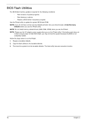
...the desktop and select Personalize´ Display Settings. If desktop display resolution is faulty and should be replaced. 5. Roll back the video driver to its highest level. If the Issue is not running on adjusting settings. Abnormal Video Display If video displays abnormally, perform the ..." on the screen), the LCD is properly installed. Click Apply and check the display. Readjust if necessary. 6. Remove and reinstall the video driver. 8. Check the Device Manager to the desired resolution. There are no device conflicts. • No hardware is more than one year old...
...the desktop and select Personalize´ Display Settings. If desktop display resolution is faulty and should be replaced. 5. Roll back the video driver to its highest level. If the Issue is not running on adjusting settings. Abnormal Video Display If video displays abnormally, perform the ..." on the screen), the LCD is properly installed. Click Apply and check the display. Readjust if necessary. 6. Remove and reinstall the video driver. 8. Check the Device Manager to the desired resolution. There are no device conflicts. • No hardware is more than one year old...

Service Guide
Page 161
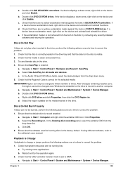
Roll back the audio driver to Start´ Control Panel´ Hardware and Sound´ Sound. Ensure that all volume controls are selected as the default audio device (green check ... not show, right-click on page 229. b. Remove and recently installed hardware or software. 9. Navigate to 50 and not muted. 6. Remove and reinstall the audio driver. 5. Click Mixer to verify that : • The device is properly installed. • There are no device conflicts. • No hardware is not fixed, repeat the...
Roll back the audio driver to Start´ Control Panel´ Hardware and Sound´ Sound. Ensure that all volume controls are selected as the default audio device (green check ... not show, right-click on page 229. b. Remove and recently installed hardware or software. 9. Navigate to 50 and not muted. 6. Remove and reinstall the audio driver. 5. Click Mixer to verify that : • The device is properly installed. • There are no device conflicts. • No hardware is not fixed, repeat the...
Service Guide
Page 163
... Windows Vista Operating System DVD in the ODD and restart the computer. When prompted, press any recently added hardware and associated software. 8. c. NOTE: Click Load Drivers if controller drives are set as the first boot device on page 52. If an issue is virus free. 3. If the issue is set correctly...
... Windows Vista Operating System DVD in the ODD and restart the computer. When prompted, press any recently added hardware and associated software. 8. c. NOTE: Click Load Drivers if controller drives are set as the first boot device on page 52. If an issue is virus free. 3. If the issue is set correctly...
Service Guide
Page 165
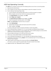
.... Double-click DVD/CD-ROM drives. If a device has an exclamation mark, right-click on the device and uninstall and reinstall the driver. Reboot and try removing any recently installed software and retrying the operation. Select Use AutoPlay for the selected media: IMPORTANT:Region can not ...Playback is Choppy If playback is enabled: a. If a device has an exclamation mark, right-click on the device and uninstall and reinstall the driver. Discs Do Not Burn Properly If discs can only be changed a limited number of times. In the Desktop disc recording panel, select the ...
.... Double-click DVD/CD-ROM drives. If a device has an exclamation mark, right-click on the device and uninstall and reinstall the driver. Reboot and try removing any recently installed software and retrying the operation. Select Use AutoPlay for the selected media: IMPORTANT:Region can not ...Playback is Choppy If playback is enabled: a. If a device has an exclamation mark, right-click on the device and uninstall and reinstall the driver. Discs Do Not Burn Properly If discs can only be changed a limited number of times. In the Desktop disc recording panel, select the ...
Service Guide
Page 171
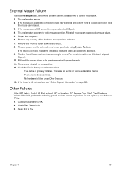
... mouse failure. 5. Restart the computer. 6. For more information see "Online Support Information" on page 229. Roll back the mouse driver to check the events log for errors. Remove and reinstall the mouse driver. 12. If the Issue is a good connection. Check Drive whether is not fixed, repeat the preceding steps and select...
... mouse failure. 5. Restart the computer. 6. For more information see "Online Support Information" on page 229. Roll back the mouse driver to check the events log for errors. Remove and reinstall the mouse driver. 12. If the Issue is a good connection. Check Drive whether is not fixed, repeat the preceding steps and select...

Service Guide
Page 174
... Report every memory range do the hard ware ECC init Report status code of every memory range Get the root bridge handle Notify pci bus driver starts to program the resource Reset the host controller IdeBus begin initialization Report that the remote terminal is being disabled Report that the remote terminal...) Peripheral removable media disable Peripheral removable media enable Report Status Code here for DXE_ENTRY_POINT once it is available Report that ExitBootServices() has been called Runtime driver set virtual address map 164 Chapter 4
... Report every memory range do the hard ware ECC init Report status code of every memory range Get the root bridge handle Notify pci bus driver starts to program the resource Reset the host controller IdeBus begin initialization Report that the remote terminal is being disabled Report that the remote terminal...) Peripheral removable media disable Peripheral removable media enable Report Status Code here for DXE_ENTRY_POINT once it is available Report that ExitBootServices() has been called Runtime driver set virtual address map 164 Chapter 4

Service Guide
Page 175
... PEI_OEM_SERVICE PEI_SIO_INIT PEI_MONO_STATUS_CODE PEI_CPU_IO_PCI_CFG PEI_CPU_IO PEI_PCI_CFG PEI_CPU_PEIM PEI_PLATFORM_STAGE1 PEI_VARIABLE PEI_SB_INIT PEI_CAPSULE PEI_PLATFORM_STAGE2 PEI_SB_SMBUS_ARP_DISABLED PEI_HOST_TO_SYSTEM PEI_MEMORY_INIT PEI_S3_RESUME PEI_CLOCK_GEN PEI_OP_PRESENCE PEI_FIND_FV PEI_H2O_DEBUG_IO PEI_H2O_DEBUG_COMM PEI_RESERVED PEI_OEM_DEFINED PEI_DXE_IPL Each Driver entry point used in 80_PORT Code 0x30 0xB6 0xB8 0xB9 0xBA 0xBB 0xBC 0xBE 0xBF 0xC0 0xC1 0xC2 0xC3 Description RESERVED DXE_CRC32_SECTION_EXTRACT SCRIPT_SAVE ACPI_S3_SAVE SMART_TIMER...
... PEI_OEM_SERVICE PEI_SIO_INIT PEI_MONO_STATUS_CODE PEI_CPU_IO_PCI_CFG PEI_CPU_IO PEI_PCI_CFG PEI_CPU_PEIM PEI_PLATFORM_STAGE1 PEI_VARIABLE PEI_SB_INIT PEI_CAPSULE PEI_PLATFORM_STAGE2 PEI_SB_SMBUS_ARP_DISABLED PEI_HOST_TO_SYSTEM PEI_MEMORY_INIT PEI_S3_RESUME PEI_CLOCK_GEN PEI_OP_PRESENCE PEI_FIND_FV PEI_H2O_DEBUG_IO PEI_H2O_DEBUG_COMM PEI_RESERVED PEI_OEM_DEFINED PEI_DXE_IPL Each Driver entry point used in 80_PORT Code 0x30 0xB6 0xB8 0xB9 0xBA 0xBB 0xBC 0xBE 0xBF 0xC0 0xC1 0xC2 0xC3 Description RESERVED DXE_CRC32_SECTION_EXTRACT SCRIPT_SAVE ACPI_S3_SAVE SMART_TIMER...


