
Aspire 4735ZG/4935/4935G Quick Guide
Page 11
... 5100/5300* • Wi-Fi®/WiMAX™: • Intel® Wireless WiFi Link 5150/5350* • WPAN: Bluetooth® 2.0+Enhanced Data Rate (EDR)* • LAN: Gigabit Ethernet; Wake-on -Ring ready • Acer Bio-Protection fingerprint solution* • BIOS user, supervisor, HDD passwords • Kensington lock slot • 342 (W) x 239 (D) x 23...
... 5100/5300* • Wi-Fi®/WiMAX™: • Intel® Wireless WiFi Link 5150/5350* • WPAN: Bluetooth® 2.0+Enhanced Data Rate (EDR)* • LAN: Gigabit Ethernet; Wake-on -Ring ready • Acer Bio-Protection fingerprint solution* • BIOS user, supervisor, HDD passwords • Kensington lock slot • 342 (W) x 239 (D) x 23...

Service Guide
Page 8
...Bracket 84 Removing the eKey Board 86 Removing the Media Board 87 Removing the USB Board 89 Removing the Modem Module 91 Removing the Bluetooth Module 92 Removing the Mainboard 93 Removing the RJ-11 Port 95 Removing the Thermal Module 97 Removing the CPU 99 LCD Module ...Reassembly Procedure 117 Replacing the CPU 117 Replacing the Thermal Module 118 Replacing the RJ-11 Port 119 Replacing the Mainboard 121 Replacing the Bluetooth Board 122 Replacing the Modem Module 122 Replacing the Finger Print Reader 126 Replacing the Upper Cover 127 Replacing the LCD Module 130 Replacing...
...Bracket 84 Removing the eKey Board 86 Removing the Media Board 87 Removing the USB Board 89 Removing the Modem Module 91 Removing the Bluetooth Module 92 Removing the Mainboard 93 Removing the RJ-11 Port 95 Removing the Thermal Module 97 Removing the CPU 99 LCD Module ...Reassembly Procedure 117 Replacing the CPU 117 Replacing the Thermal Module 118 Replacing the RJ-11 Port 119 Replacing the Mainboard 121 Replacing the Bluetooth Board 122 Replacing the Modem Module 122 Replacing the Finger Print Reader 126 Replacing the Upper Cover 127 Replacing the LCD Module 130 Replacing...
Service Guide
Page 9
...HDD Not Operating Correctly 153 ODD Failure 154 USB Failure (Rightside 157 Modem Function Failure 157 Wireless Function Failure 158 Bluetooth Function Failure 158 EasyTouch Button Failure 159 Media Board Failure 159 Fingerprint Reader Failure 160 Thermal Unit Failure 160 External...Recovery by Crisis Disk 172 FRU (Field Replaceable Unit) List 173 Aspire 4935/4935G Exploded Diagrams 174 Main Module 174 Aspire 4935/4935G FRU List 175 Screw List 182 Model Definition and Configuration 184 Aspire 4935/4935G Series 184 Test Compatible Components 223 Microsoft® Windows®...
...HDD Not Operating Correctly 153 ODD Failure 154 USB Failure (Rightside 157 Modem Function Failure 157 Wireless Function Failure 158 Bluetooth Function Failure 158 EasyTouch Button Failure 159 Media Board Failure 159 Fingerprint Reader Failure 160 Thermal Unit Failure 160 External...Recovery by Crisis Disk 172 FRU (Field Replaceable Unit) List 173 Aspire 4935/4935G Exploded Diagrams 174 Main Module 174 Aspire 4935/4935G FRU List 175 Screw List 182 Model Definition and Configuration 184 Aspire 4935/4935G Series 184 Test Compatible Components 223 Microsoft® Windows®...
Service Guide
Page 12
... x 239 (D) x 23/38.6 (H) mm (13.4 x 9.4 x 0.9/1.5 inches) • 2.4 kg (5.30 lbs.) with 6-cell battery Privacy control • Acer Bio-Protection fingerprint solution* • BIOS user, supervisor, HDD passwords • Kensington lock slot Power subsystem • ACPI 3.0 • 48.8 W 4400 mAh •...; Integrated Acer Crystal Eye webcam* • Acer PureZone technology* • Optional Acer Xpress VoIP phone* • WLAN: • Intel® Wireless WiFi Link 5100/5300* • Wi-Fi®/WiMAX™: • Intel® Wireless WiFi Link 5150/5350* • WPAN: Bluetooth® ...
... x 239 (D) x 23/38.6 (H) mm (13.4 x 9.4 x 0.9/1.5 inches) • 2.4 kg (5.30 lbs.) with 6-cell battery Privacy control • Acer Bio-Protection fingerprint solution* • BIOS user, supervisor, HDD passwords • Kensington lock slot Power subsystem • ACPI 3.0 • 48.8 W 4400 mAh •...; Integrated Acer Crystal Eye webcam* • Acer PureZone technology* • Optional Acer Xpress VoIP phone* • WLAN: • Intel® Wireless WiFi Link 5100/5300* • Wi-Fi®/WiMAX™: • Intel® Wireless WiFi Link 5150/5350* • WPAN: Bluetooth® ...

Service Guide
Page 20
... charging. 2. The mail and Web browser buttons are pre-set the Web browser, mail and programmable buttons, run the Acer Launch Manager. NOTE: 1. These buttons are : WLAN, Internet, email, Bluetooth, Arcade and Acer Empowering Technology. They are called easy-launch buttons. Icon Function Wireless communication switch Web browser Description Enables/disables the wireless...
... charging. 2. The mail and Web browser buttons are pre-set the Web browser, mail and programmable buttons, run the Acer Launch Manager. NOTE: 1. These buttons are : WLAN, Internet, email, Bluetooth, Arcade and Acer Empowering Technology. They are called easy-launch buttons. Icon Function Wireless communication switch Web browser Description Enables/disables the wireless...
Service Guide
Page 37
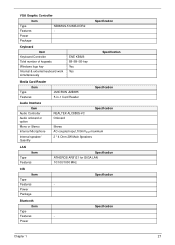
... 2W Main Speakers LAN Item Type Features Specification ATHEROS AR8121 for GIGA LAN 10/100/1000 MHz CIR Item Type Features • Power Package Specification Bluetooth Item Type Features • Power Specification Chapter 1 27
... 2W Main Speakers LAN Item Type Features Specification ATHEROS AR8121 for GIGA LAN 10/100/1000 MHz CIR Item Type Features • Power Package Specification Bluetooth Item Type Features • Power Specification Chapter 1 27

Service Guide
Page 75
... ove Fingerprint Reader Rem ove eKey Board Rem ove Media Board Rem ove TouchPad Bracket Rem ove USB Board Rem ove Modem Module Rem ove Bluetooth Module Rem ove Mainboard Rem ove RJ-11 Port Rem ove Thermal Module Screw List Step Hinge Covers Switch Cover Function Board Speaker Module LCD...
... ove Fingerprint Reader Rem ove eKey Board Rem ove Media Board Rem ove TouchPad Bracket Rem ove USB Board Rem ove Modem Module Rem ove Bluetooth Module Rem ove Mainboard Rem ove RJ-11 Port Rem ove Thermal Module Screw List Step Hinge Covers Switch Cover Function Board Speaker Module LCD...

Service Guide
Page 102
Removing the Bluetooth Module 1. Grasp the cable as shown and pull to free the cable. 4. See "Removing the Upper Base" on page 79. 2. Remove the single securing screw and remove the module from the Bluetooth module. 3. Disconnect the cable from the Mainboard and remove the adhesive tape to disconnect from the chassis. Step Bluetooth Module Size M2.5*3 Quantity 1 Screw Type 92 Chapter 3
Removing the Bluetooth Module 1. Grasp the cable as shown and pull to free the cable. 4. See "Removing the Upper Base" on page 79. 2. Remove the single securing screw and remove the module from the Bluetooth module. 3. Disconnect the cable from the Mainboard and remove the adhesive tape to disconnect from the chassis. Step Bluetooth Module Size M2.5*3 Quantity 1 Screw Type 92 Chapter 3

Service Guide
Page 103
See "Removing the Upper Base" on page 91. 4. See "Removing the Modem Module" on page 79. 2. See "Removing the Bluetooth Module" on page 89. 3. Grasp the RJ-11 cable and remove it from the Mainboard as shown. 6. Remove the single securing screw. Removing the Mainboard 1. Step Mainboard Size M2.5*3 Quantity 1 Screw Type Chapter 3 93 See "Removing the USB Board" on page 92. 5.
See "Removing the Upper Base" on page 91. 4. See "Removing the Modem Module" on page 79. 2. See "Removing the Bluetooth Module" on page 89. 3. Grasp the RJ-11 cable and remove it from the Mainboard as shown. 6. Remove the single securing screw. Removing the Mainboard 1. Step Mainboard Size M2.5*3 Quantity 1 Screw Type Chapter 3 93 See "Removing the USB Board" on page 92. 5.

Service Guide
Page 132
Replacing the Bluetooth Board 1. Reconnect the Bluetooth cable to the Mainboard 4. Replace the Modem Module on the Mainboard. 122 Chapter 3 Reconnect the Bluetooth cable to the Bluetooth and secure the cable in place with the tape. Connect the modem cable as shown. 2. Insert the Bluetooth Module left side first and lower 2. it into place. 3. Module. Replacing the Modem Module 1. Replace the single securing screw.
Replacing the Bluetooth Board 1. Reconnect the Bluetooth cable to the Mainboard 4. Replace the Modem Module on the Mainboard. 122 Chapter 3 Reconnect the Bluetooth cable to the Bluetooth and secure the cable in place with the tape. Connect the modem cable as shown. 2. Insert the Bluetooth Module left side first and lower 2. it into place. 3. Module. Replacing the Modem Module 1. Replace the single securing screw.
Service Guide
Page 155
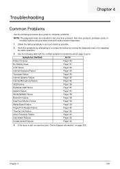
...Microphone Failure Page 152 ODD Failure Page 154 Rightside USB Failure Page 157 Modem Failure Page 157 WLAN/WiMAX Failure Page 158 Bluetooth Failure Page 158 EasyTouch Button Failure Page 159 Media Board Failure Page 159 Finger Print Reader Failure Page 160 Thermal Unit ... Page 162 4. Troubleshooting Chapter 4 Common Problems Use the following table with the verified symptom to determine which page to go to. Non-Acer products, prototype cards, or modified options can give false errors and invalid system responses. 1. Obtain the failing symptoms in as much detail...
...Microphone Failure Page 152 ODD Failure Page 154 Rightside USB Failure Page 157 Modem Failure Page 157 WLAN/WiMAX Failure Page 158 Bluetooth Failure Page 158 EasyTouch Button Failure Page 159 Media Board Failure Page 159 Finger Print Reader Failure Page 160 Thermal Unit ... Page 162 4. Troubleshooting Chapter 4 Common Problems Use the following table with the verified symptom to determine which page to go to. Non-Acer products, prototype cards, or modified options can give false errors and invalid system responses. 1. Obtain the failing symptoms in as much detail...

Service Guide
Page 168
... the Antenna OK Check WLAN/Wi MAX Card NG Swap WLAN/ WiMAX Card OK Check Function Board NG Swap Function Board Swap Mainboard Bluetooth Function Failure If the Bluetooth fails, perform the following actions one at a time to the module Check BT cable NG Swap the cable OK Check BT Module NG...
... the Antenna OK Check WLAN/Wi MAX Card NG Swap WLAN/ WiMAX Card OK Check Function Board NG Swap Function Board Swap Mainboard Bluetooth Function Failure If the Bluetooth fails, perform the following actions one at a time to the module Check BT cable NG Swap the cable OK Check BT Module NG...

Service Guide
Page 179
... SW2 LED2 LED1 SW1 JEXP1 Description FP Board Connector Keyboard Connector Function Board Connector e-Key Board Connector Media Console Connector USB Board Connector MiniCard Port Bluetooth Connector MDC Connector Switch Battery LED Power LED Switch ExpressCard Connector 169
... SW2 LED2 LED1 SW1 JEXP1 Description FP Board Connector Keyboard Connector Function Board Connector e-Key Board Connector Media Console Connector USB Board Connector MiniCard Port Bluetooth Connector MDC Connector Switch Battery LED Power LED Switch ExpressCard Connector 169
Service Guide
Page 186
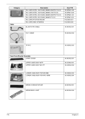
... SIN/PHI FCC/IC W/L CARD INTEL 3X3 533AN_MMWG FCC/IC W/L CARD RT2700E RALINK W/L CARD XB91 ATHEROS Acer P/N KI.SPM01.003 KI.SPM01.003 KI.SPM01.001 KI.SPM01.001 NI.23600.031 NI.23600.030 BLUETOOTH CABLE 50.AD302.001 RJ11 CABLE 50.AD302.002 TP FFC Case/Cover/Bracket Assembly STRIP...
... SIN/PHI FCC/IC W/L CARD INTEL 3X3 533AN_MMWG FCC/IC W/L CARD RT2700E RALINK W/L CARD XB91 ATHEROS Acer P/N KI.SPM01.003 KI.SPM01.003 KI.SPM01.001 KI.SPM01.001 NI.23600.031 NI.23600.030 BLUETOOTH CABLE 50.AD302.001 RJ11 CABLE 50.AD302.002 TP FFC Case/Cover/Bracket Assembly STRIP...

Service Guide
Page 234
... 60002015 HIPRO Audio Codec 9999995 ONE TIME VENDER 9999995 ONE TIME VENDER Battery 10001063 SONY 60001535 PANASONIC 60002162 SIMPLO 60002162 SIMPLO 60001921 SANYO 60002162 SIMPLO Bluetooth 9999995 ONE TIME VENDER Camera 9999995 ONE TIME VENDER Card Reader 9999995 ONE TIME VENDER CPU 10001067 INTEL Type 65W 65W 65W 90W 90W 90W...
... 60002015 HIPRO Audio Codec 9999995 ONE TIME VENDER 9999995 ONE TIME VENDER Battery 10001063 SONY 60001535 PANASONIC 60002162 SIMPLO 60002162 SIMPLO 60001921 SANYO 60002162 SIMPLO Bluetooth 9999995 ONE TIME VENDER Camera 9999995 ONE TIME VENDER Card Reader 9999995 ONE TIME VENDER CPU 10001067 INTEL Type 65W 65W 65W 90W 90W 90W...

Service Guide
Page 241
... BIOS Utility 29-42 Boot 40 Exit 41 Navigating 29 Onboard Device Configuration 36 Power 38 Save and Exit 41 Security 35 System Security 41 Bluetooth module 92 Board Layout Top View 169 brightness hotkeys 14 C Camera Module 103 caps lock on indicator 10 Common Problems 146 computer on indicator 10...
... BIOS Utility 29-42 Boot 40 Exit 41 Navigating 29 Onboard Device Configuration 36 Power 38 Save and Exit 41 Security 35 System Security 41 Bluetooth module 92 Board Layout Top View 169 brightness hotkeys 14 C Camera Module 103 caps lock on indicator 10 Common Problems 146 computer on indicator 10...


