
Aspire 4735ZG/4935/4935G Quick Guide
Page 9
Note: Do not cover or obstruct the opening of the fan. English 9 Base view 1 2 6 5 4 3 # Icon Item 1 Battery bay Description Houses the computer's battery pack. 2 Battery release latch Releases the battery for removal. 3 Hard disk bay Houses the computer's hard disk (secured with screws). 4 Memory compartment Houses the computer's main memory. 5 Battery lock Locks the battery in position. 6 Ventilation slots and Enable the computer to stay cool, even cooling fan after prolonged use.
Note: Do not cover or obstruct the opening of the fan. English 9 Base view 1 2 6 5 4 3 # Icon Item 1 Battery bay Description Houses the computer's battery pack. 2 Battery release latch Releases the battery for removal. 3 Hard disk bay Houses the computer's hard disk (secured with screws). 4 Memory compartment Houses the computer's main memory. 5 Battery lock Locks the battery in position. 6 Ventilation slots and Enable the computer to stay cool, even cooling fan after prolonged use.

Aspire 4735ZG/4935/4935G Quick Guide
Page 11
...® 2.0+Enhanced Data Rate (EDR)* • LAN: Gigabit Ethernet; Wake-on -LAN ready • Modem: 56K ITU V.92; Wake-on -Ring ready • Acer Bio-Protection fingerprint solution* • BIOS user, supervisor, HDD passwords • Kensington lock slot • 342 (W) x 239 (D) x 23/38.6 (H) mm (13.4... x 9.4 x 0.9/1.5 inches) • 2.4 kg (5.30 lbs.) with 6-cell battery • ACPI 3.0 • 48.8 W 4400 mAh • 3-pin 65 W AC adapter* • 3-pin 90 W AC adapter* • ENERGY STAR® 4.0* •...
...® 2.0+Enhanced Data Rate (EDR)* • LAN: Gigabit Ethernet; Wake-on -LAN ready • Modem: 56K ITU V.92; Wake-on -Ring ready • Acer Bio-Protection fingerprint solution* • BIOS user, supervisor, HDD passwords • Kensington lock slot • 342 (W) x 239 (D) x 23/38.6 (H) mm (13.4... x 9.4 x 0.9/1.5 inches) • 2.4 kg (5.30 lbs.) with 6-cell battery • ACPI 3.0 • 48.8 W 4400 mAh • 3-pin 65 W AC adapter* • 3-pin 90 W AC adapter* • ENERGY STAR® 4.0* •...

Service Guide
Page 7
...12 Lock Keys and embedded numeric keypad 12 Windows Keys 13 Hot Keys 14 Special Key 15 Using the System Utilities 16 Acer GridVista (dual-display compatible 16 Hardware Specifications and Configurations 18 System Utilities 29 BIOS Setup Utility 29 Navigating the BIOS Utility ...General Information 52 Pre-disassembly Instructions 52 Disassembly Process 52 External Module Disassembly Process 53 External Modules Disassembly Flowchart 53 Removing the Battery Pack 54 Removing the SD dummy card 55 Removing the ExpressCard dummy card 56 Removing the Lower Covers 57 Removing the WLAN...
...12 Lock Keys and embedded numeric keypad 12 Windows Keys 13 Hot Keys 14 Special Key 15 Using the System Utilities 16 Acer GridVista (dual-display compatible 16 Hardware Specifications and Configurations 18 System Utilities 29 BIOS Setup Utility 29 Navigating the BIOS Utility ...General Information 52 Pre-disassembly Instructions 52 Disassembly Process 52 External Module Disassembly Process 53 External Modules Disassembly Flowchart 53 Removing the Battery Pack 54 Removing the SD dummy card 55 Removing the ExpressCard dummy card 56 Removing the Lower Covers 57 Removing the WLAN...

Service Guide
Page 8
... the DIMM Modules 141 Replacing the WLAN Module 142 Replacing the Lower Covers 142 Replacing the ExpressCard and SD Card Dummy Trays 143 Replacing the Battery 143 VIII
... the DIMM Modules 141 Replacing the WLAN Module 142 Replacing the Lower Covers 142 Replacing the ExpressCard and SD Card Dummy Trays 143 Replacing the Battery 143 VIII
Service Guide
Page 12
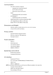
Wake-on -LAN ready • Modem: 56K ITU V.92; Communication • Acer Video Conference, featuring: • Integrated Acer Crystal Eye webcam* • Acer PureZone technology* • Optional Acer Xpress VoIP phone* • WLAN: • Intel® Wireless WiFi Link 5100/5300*...8226; 342 (W) x 239 (D) x 23/38.6 (H) mm (13.4 x 9.4 x 0.9/1.5 inches) • 2.4 kg (5.30 lbs.) with 6-cell battery Privacy control • Acer Bio-Protection fingerprint solution* • BIOS user, supervisor, HDD passwords • Kensington lock slot Power subsystem • ACPI 3.0 • 48.8 W 4400 ...
Wake-on -LAN ready • Modem: 56K ITU V.92; Communication • Acer Video Conference, featuring: • Integrated Acer Crystal Eye webcam* • Acer PureZone technology* • Optional Acer Xpress VoIP phone* • WLAN: • Intel® Wireless WiFi Link 5100/5300*...8226; 342 (W) x 239 (D) x 23/38.6 (H) mm (13.4 x 9.4 x 0.9/1.5 inches) • 2.4 kg (5.30 lbs.) with 6-cell battery Privacy control • Acer Bio-Protection fingerprint solution* • BIOS user, supervisor, HDD passwords • Kensington lock slot Power subsystem • ACPI 3.0 • 48.8 W 4400 ...

Service Guide
Page 19
Houses the computer's main memory. Note: Do not cover or obstruct the opening of the fan. Houses the computer's hard disk (secured with screws). Releases the battery for removal. Enable the computer to stay cool, even after prolonged use. Chapter 1 9 Locks the battery in position. Bottom View No. 1 2 3 4 5 6 Icon Item Battery bay Battery release latch Hard disk bay Memory compartment Battery lock Ventilation slots and cooling fan Description Houses the computer's battery pack.
Houses the computer's main memory. Note: Do not cover or obstruct the opening of the fan. Houses the computer's hard disk (secured with screws). Releases the battery for removal. Enable the computer to stay cool, even after prolonged use. Chapter 1 9 Locks the battery in position. Bottom View No. 1 2 3 4 5 6 Icon Item Battery bay Battery release latch Hard disk bay Memory compartment Battery lock Ventilation slots and cooling fan Description Houses the computer's battery pack.

Service Guide
Page 20
...battery is activated. They are application buttons. Internet browser (user-Programmable) Mail Email application (user-Programmable) Bluetooth communication switch Empowering Technology Enables/disables the Bluetooth function. The mail and Web browser buttons are pre-set the Web browser, mail and programmable buttons, run the Acer... programs, but can be reset by users. These buttons are called easy-launch buttons. Battery HDD Num Lock Caps Lock Indicates the computer's battery status. Indicates when the hard disk drive is active. To set to -read status ...
...battery is activated. They are application buttons. Internet browser (user-Programmable) Mail Email application (user-Programmable) Bluetooth communication switch Empowering Technology Enables/disables the Bluetooth function. The mail and Web browser buttons are pre-set the Web browser, mail and programmable buttons, run the Acer... programs, but can be reset by users. These buttons are called easy-launch buttons. Battery HDD Num Lock Caps Lock Indicates the computer's battery status. Indicates when the hard disk drive is active. To set to -read status ...
Service Guide
Page 52
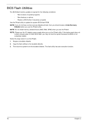
... required for the following conditions: • New versions of system programs • New features or options • Restore a BIOS when it becomes corrupted. If the battery pack does not contain enough power to run the Phlash utility. NOTE: Please use the AC adaptor power supply when you use the Phlash. The...
... required for the following conditions: • New versions of system programs • New features or options • Restore a BIOS when it becomes corrupted. If the battery pack does not contain enough power to run the Phlash utility. NOTE: Please use the AC adaptor power supply when you use the Phlash. The...

Service Guide
Page 62
...• External module disassembly • Main unit disassembly • LCD module disassembly The flowcharts provided in that order. Main Screw List Description Quantity Acer P/N M2.0D 3.0L K4.6D 0.8T ZK 17 86.AD302.001 M2.5D 3.0L K5.5D 0.8T ZK 15 86.AD302.002 M2.....004 M3.0D 3.0L K 4.9D NI+ 4 86.AD302.005 M2.5D 3.2L K 6D NI+ 4 86.AD302.006 52 Chapter 3 Remove the battery pack. Disassembly Process The disassembly process is divided into the following : 1. General Information Pre-disassembly Instructions Before proceeding with the disassembly procedure, make sure that...
...• External module disassembly • Main unit disassembly • LCD module disassembly The flowcharts provided in that order. Main Screw List Description Quantity Acer P/N M2.0D 3.0L K4.6D 0.8T ZK 17 86.AD302.001 M2.5D 3.0L K5.5D 0.8T ZK 15 86.AD302.002 M2.....004 M3.0D 3.0L K 4.9D NI+ 4 86.AD302.005 M2.5D 3.2L K 6D NI+ 4 86.AD302.006 52 Chapter 3 Remove the battery pack. Disassembly Process The disassembly process is divided into the following : 1. General Information Pre-disassembly Instructions Before proceeding with the disassembly procedure, make sure that...

Service Guide
Page 63
Turn off system and peripherals power Disconnect power and signal cables from system Rem ove Battery Rem ove SD Dummy Rem ove NewCard Dummy Rem ove Lower Covers Rem ove WLAN Rem ove DIMMs Rem ove HDD Rem ove ODD Screw ...
Turn off system and peripherals power Disconnect power and signal cables from system Rem ove Battery Rem ove SD Dummy Rem ove NewCard Dummy Rem ove Lower Covers Rem ove WLAN Rem ove DIMMs Rem ove HDD Rem ove ODD Screw ...

Service Guide
Page 64
Slide and hold the battery release latch to the unlock position. 3. Removing the Battery Pack 1. Slide the battery lock/unlock latch to the release position (1), then lift out the battery pack from the main unit (2). 2 1 54 Chapter 3 Turn computer over. 2.
Slide and hold the battery release latch to the unlock position. 3. Removing the Battery Pack 1. Slide the battery lock/unlock latch to the release position (1), then lift out the battery pack from the main unit (2). 2 1 54 Chapter 3 Turn computer over. 2.

Service Guide
Page 67
Loosen the five captive screws in the covers as shown. Carefully open the DIMM Cover. HDD Cover 6. Removing the Lower Covers 1. See "Removing the ExpressCard dummy card" on page 55. 3. Chapter 3 57 Remove the WLAN Cover as shown. See "Removing the SD dummy card" on page 56. 4. DIMM Cover WLAN Cover 5. See "Removing the Battery Pack" on page 54. 2.
Loosen the five captive screws in the covers as shown. Carefully open the DIMM Cover. HDD Cover 6. Removing the Lower Covers 1. See "Removing the ExpressCard dummy card" on page 55. 3. Chapter 3 57 Remove the WLAN Cover as shown. See "Removing the SD dummy card" on page 56. 4. DIMM Cover WLAN Cover 5. See "Removing the Battery Pack" on page 54. 2.

Service Guide
Page 77
See "Removing the Battery Pack" on the inside. Ensure that the correct cover is used during reassembly. Remove the two screw caps and screws from the Hinge Covers. Slide the covers off the hinges in the direction of the arrows. IMPORTANT:The left and right Hinge Covers are shaped differently and marked L and R on page 54. 2. Removing the Hinge Covers 1. Chapter 3 67 Step Hinge Covers Size M2*3 Quantity 2 Screw Type 3.
See "Removing the Battery Pack" on the inside. Ensure that the correct cover is used during reassembly. Remove the two screw caps and screws from the Hinge Covers. Slide the covers off the hinges in the direction of the arrows. IMPORTANT:The left and right Hinge Covers are shaped differently and marked L and R on page 54. 2. Removing the Hinge Covers 1. Chapter 3 67 Step Hinge Covers Size M2*3 Quantity 2 Screw Type 3.

Service Guide
Page 78
... Cover. 1. Locate and remove the ten securing screws on the bottom of the cover upward (2) to release the securing pins. 1 2 68 Chapter 3 See "Removing the Battery Pack" on page 67. 3.
... Cover. 1. Locate and remove the ten securing screws on the bottom of the cover upward (2) to release the securing pins. 1 2 68 Chapter 3 See "Removing the Battery Pack" on page 67. 3.

Service Guide
Page 153
Insert the SD Card and push into the slot until flush flush with the chassis cover. Slide the battery lock/unlock latch to the release position (1), then insert the battery and press down (2). 2. Slide and hold the battery release latch to the lock position. 2 1 Chapter 3 143 Replacing the Battery 1. Insert the ExpressCard and push into the slot until 2. with the chassis cover. Replacing the ExpressCard and SD Card Dummy Trays 1.
Insert the SD Card and push into the slot until flush flush with the chassis cover. Slide the battery lock/unlock latch to the release position (1), then insert the battery and press down (2). 2. Slide and hold the battery release latch to the lock position. 2 1 Chapter 3 143 Replacing the Battery 1. Insert the ExpressCard and push into the slot until 2. with the chassis cover. Replacing the ExpressCard and SD Card Dummy Trays 1.

Service Guide
Page 157
... by one at a time to correct the problem. 1. Chapter 4 147 If the computer boots correctly, add the devices one by removing the power cable and battery and holding down the power button for specific model procedures. 2. Reconnect the power and reboot the computer. 4. Remove the drives (see "Online Support Information" on...
... by one at a time to correct the problem. 1. Chapter 4 147 If the computer boots correctly, add the devices one by removing the power cable and battery and holding down the power button for specific model procedures. 2. Reconnect the power and reboot the computer. 4. Remove the drives (see "Online Support Information" on...
Service Guide
Page 158
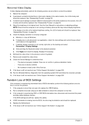
... Personalize´ Display Settings. d. Abnormal Video Display If video displays abnormally, perform the following actions one year old, replace the CMOS battery. 2. If permanent vertical/horizontal lines or dark spots display in the same location, the LCD is only abnormal in an application, check... the view settings and control/mouse wheel zoom feature in the same locations on battery alone as this may be defective and should be replaced. 5. See "Disassembly Process" on page 229. 10. Replace the Motherboard. 6....
... Personalize´ Display Settings. d. Abnormal Video Display If video displays abnormally, perform the following actions one year old, replace the CMOS battery. 2. If permanent vertical/horizontal lines or dark spots display in the same location, the LCD is only abnormal in an application, check... the view settings and control/mouse wheel zoom feature in the same locations on battery alone as this may be defective and should be replaced. 5. See "Disassembly Process" on page 229. 10. Replace the Motherboard. 6....
Service Guide
Page 171
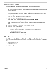
... software. 7. Roll back the mouse driver to Try. Swap M/B to the previous version if updated recently. 11. If the mouse uses a wireless connection, insert new batteries and confirm there is properly installed. Run the Event Viewer to verify mouse operation. Check Drive whether is not fixed, repeat the preceding steps and...
... software. 7. Roll back the mouse driver to Try. Swap M/B to the previous version if updated recently. 11. If the mouse uses a wireless connection, insert new batteries and confirm there is properly installed. Run the Event Viewer to verify mouse operation. Check Drive whether is not fixed, repeat the preceding steps and...

Service Guide
Page 172
... being used at least 10 times. 2. Visually check them for the system board in loop mode at the time of the following devices: • Non-Acer devices • Printer, mouse, and other external devices • Battery pack • Hard disk drive • DIMM • CD-ROM/Diskette drive Module • PC Cards 4.
... being used at least 10 times. 2. Visually check them for the system board in loop mode at the time of the following devices: • Non-Acer devices • Printer, mouse, and other external devices • Battery pack • Hard disk drive • DIMM • CD-ROM/Diskette drive Module • PC Cards 4.

Service Guide
Page 179
... Description FP Board Connector Keyboard Connector Function Board Connector e-Key Board Connector Media Console Connector USB Board Connector MiniCard Port Bluetooth Connector MDC Connector Switch Battery LED Power LED Switch ExpressCard Connector 169
... Description FP Board Connector Keyboard Connector Function Board Connector e-Key Board Connector Media Console Connector USB Board Connector MiniCard Port Bluetooth Connector MDC Connector Switch Battery LED Power LED Switch ExpressCard Connector 169


