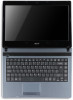
Acer Aspire 4339 4739 4739Z Notebook Series Service Guide
Page 7
... 3-5 General Information 3-5 Recommended Equipment 3-5 Maintenance Flowchart 3-6 Getting Started 3-7 Battery Pack Removal 3-8 Battery Pack Installation 3-8 Dummy Card Removal 3-9 Dummy Card Installation 3-9 Keyboard Removal 3-10 Keyboard Installation 3-11 Base Assembly Removal 3-12 Base Assembly Installation 3-13 ODD (Optical Disk Drive) Module Removal 3-14 ODD Module Installation 3-15 USB Module Removal 3-16 USB Module Installation 3-17 HDD (Hard Disk Drive) Module...
Acer Aspire 4339 4739 4739Z Notebook Series Service Guide
Page 8
... Bezel Installation 3-38 Camera Module Removal 3-39 Camera Module Installation 3-40 LCD Panel Removal 3-41 LCD Panel Installation 3-42 LCD Bracket Removal 3-43 LCD Bracket Installation 3-43 LVDS Cable Removal 3-44 LVDS Cable Installation 3-45 CHAPTER 4 Troubleshooting Introduction 4-3 General Information 4-3 Power On Issues 4-4 No Display Issues 4-5 LCD Picture Failure 4-8 Internal Keyboard Failure 4-9 Touchpad Failure 4-10...
Acer Aspire 4339 4739 4739Z Notebook Series Service Guide
Page 86
Introduction 3-5 General Information 3-5 Recommended Equipment 3-5 Maintenance Flowchart 3-6 Getting Started 3-7 Battery Pack Removal 3-8 Battery Pack Installation 3-8 Dummy Card Removal 3-9 Dummy Card Installation 3-9 Keyboard Removal 3-10 Keyboard Installation 3-11 Base Assembly Removal 3-12 Base Assembly Installation 3-13 ODD (Optical Disk Drive) Module Removal 3-14 ODD Module Installation 3-15 USB Module Removal 3-16 USB Module Installation 3-17 HDD (Hard Disk Drive) Module...
Acer Aspire 4339 4739 4739Z Notebook Series Service Guide
Page 90
Maintenance Flowchart 0 The flowchart in Figure 3-1 shows a graphic representation of the module removal and installation sequences. It shows information on what components may need to be removed and installed during servicing. Maintenance Flow 3-6 LCD Brackets Machine Maintenance Procedures Battery SD Dummy Card Keyboard Base Assembly ODD Module USB Module Mainboard HDD Module DIMM Module WLAN Module Power Switch Board LCD Module Speaker Module Thermal Module LCD Bezel DDCC--iinn JJaackke CPU Processor LCD Panel Camera LVDS Cable Figure 3-1.
Acer Aspire 4339 4739 4739Z Notebook Series Service Guide
Page 94
Keyboard Latches 2. Disconnect keyboard FPC (A) from the system (Figure 3-5). Figure 3-5. B A C 3-10 Figure 3-6. Keyboard FPC Machine Maintenance Procedures Press upward on the palm rest (Figure 3-6). 3. Turn the keyboard over so that the keypad (C) is face down on the seven (7) locking latches until the keyboard disengages and separates from mainboard connector (B) (Figure 3-6). Keyboard Removal 0 Prerequisite: Battery Pack Removal 1.
Acer Aspire 4339 4739 4739Z Notebook Series Service Guide
Page 95
Keyboard Installation 0 1. Refer to mainboard connector (B). Machine Maintenance Procedures 3-11 Install battery. Connect keyboard FPC (A) to Figure 3-5. 5. Refer to Figure 3-6. 3. Refer to Figure 3-6. 2. Turn the keyboard over and align the keyboard with the indentation in the upper cover. 4. Press down on the system. Put the keyboard face down to secure the latches on the palm rest (C). ! CAUTION: Keyboard FPC (Flexible Printed Circuit) can be damaged if removed while mainboard connector is locked.