Aspire 3000 / 3500 / 5000 Service Guide
Page 7
Table of Contents Chapter 1 System Introduction 1 Features 1 System Block Diagram (For Aspire 3000/5000 3 System Block Diagram (For Aspire 3500 4 Board Layout (For Aspire 3000/5000 5 Top View 5 Bottom View 6 Panel 8 Front view 8 Closed front view 9 Left view 9 Right view 10 ... 16 Touchpad 18 Touchpad basics 18 Hardware Specifications and Configurations 20 BIOS Setup Utility 32 Chapter 2 System Utilities 32 Navigating the BIOS Utility 33 Information 34 Main 35 Security 37 Boot 41 Exit 42 BIOS Flash Utility 43 Chapter 3 Machine Disassembly and Replacement 46 General...
Table of Contents Chapter 1 System Introduction 1 Features 1 System Block Diagram (For Aspire 3000/5000 3 System Block Diagram (For Aspire 3500 4 Board Layout (For Aspire 3000/5000 5 Top View 5 Bottom View 6 Panel 8 Front view 8 Closed front view 9 Left view 9 Right view 10 ... 16 Touchpad 18 Touchpad basics 18 Hardware Specifications and Configurations 20 BIOS Setup Utility 32 Chapter 2 System Utilities 32 Navigating the BIOS Utility 33 Information 34 Main 35 Security 37 Boot 41 Exit 42 BIOS Flash Utility 43 Chapter 3 Machine Disassembly and Replacement 46 General...
Aspire 3000 / 3500 / 5000 Service Guide
Page 8
... Power System Check 68 Touchpad Check 70 Power-On Self-Test (POST) Error Message 71 Index of Error Messages 72 Phoenix BIOS Beep Codes 75 Index of Symptom-to-FRU Error Message 79 Intermittent Problems 82 Undetermined Problems 83 Chapter 5 Jumper and Connector ...Locations 84 Top View 84 Bottom View 86 Cahpter 6 FRU (Field Replaceable Unit) List 88 Aspire 3000/5000 Exploded Diagram 89 Aspire 3000/3500/5000 Series 101 Appendix A Model Definition and Configuration 101 Appendix B Test Compatible Components 104 Microsoft Windows XP Environment Test ...
... Power System Check 68 Touchpad Check 70 Power-On Self-Test (POST) Error Message 71 Index of Error Messages 72 Phoenix BIOS Beep Codes 75 Index of Symptom-to-FRU Error Message 79 Intermittent Problems 82 Undetermined Problems 83 Chapter 5 Jumper and Connector ...Locations 84 Top View 84 Bottom View 86 Cahpter 6 FRU (Field Replaceable Unit) List 88 Aspire 3000/5000 Exploded Diagram 89 Aspire 3000/3500/5000 Series 101 Appendix A Model Definition and Configuration 101 Appendix B Test Compatible Components 104 Microsoft Windows XP Environment Test ...
Aspire 3000 / 3500 / 5000 Service Guide
Page 10
... with dual so DIMM modules T 512 KB flash ROM BIOS for models employing Intel® Celeron® M processor (Aspire 3500 series); 2 MB flash ROM BIOS for models employing Intel® Pentium® processor (Aspire 3500 series) Data storage T T 40/60/80 GB ATA.../100 hard disk DVD-Dual or Combo drive Display and graphics T Color Thin-Film Transistor (TFT) LCD displaying at -- 15" XGA (1024 X 768) -- 15.4" WXGA (1280 X 800) -- 15.4" WXGA Acer...
... with dual so DIMM modules T 512 KB flash ROM BIOS for models employing Intel® Celeron® M processor (Aspire 3500 series); 2 MB flash ROM BIOS for models employing Intel® Pentium® processor (Aspire 3500 series) Data storage T T 40/60/80 GB ATA.../100 hard disk DVD-Dual or Combo drive Display and graphics T Color Thin-Film Transistor (TFT) LCD displaying at -- 15" XGA (1024 X 768) -- 15.4" WXGA (1280 X 800) -- 15.4" WXGA Acer...

Aspire 3000 / 3500 / 5000 Service Guide
Page 12
... Page 11,12,13 LPC EC NS PC97551 Page 20 AC97 Codec ALC203 Page 17 BIOS Page 20 AMP MAX9755 Page 18 MIC-In Jack Line-In Jack HP-Out Jack Int. System Block Diagram (For Aspire 3000/5000) 8 7 HOST 200MHz ZCLK 133MHz CLK-GEN AGP 66MHz ICS 952801 PCI 33MHz D USB...
... Page 11,12,13 LPC EC NS PC97551 Page 20 AC97 Codec ALC203 Page 17 BIOS Page 20 AMP MAX9755 Page 18 MIC-In Jack Line-In Jack HP-Out Jack Int. System Block Diagram (For Aspire 3000/5000) 8 7 HOST 200MHz ZCLK 133MHz CLK-GEN AGP 66MHz ICS 952801 PCI 33MHz D USB...

Aspire 3000 / 3500 / 5000 Service Guide
Page 14
Board Layout (For Aspire 3000/5000) Top View [13] [14] [17] [18] [21] [22] [23] [28] [31] [42] [15] [16] [19] [20] [24] [25] [26] [27] [29] [30] [32] [33] [34][35][36][41][37] [38] [39][40] 13 Power Jack 15 Battery Connector 17 302ELV LVDS Encoder 19 MINI PCI 21 CPU Socket 23 USB Connector 25 EC PC97551 27 DDR SO-DIMM Socket1 14 CRT Connector 16 ODD Connector 18 RJ45 & RJ11 Connector 20 Northbridge M760GX 22 USB Connector 24 BIOS ROM 26 RTC Battery 28 LAN PHY RTL8201CP Chapter 1 5
Board Layout (For Aspire 3000/5000) Top View [13] [14] [17] [18] [21] [22] [23] [28] [31] [42] [15] [16] [19] [20] [24] [25] [26] [27] [29] [30] [32] [33] [34][35][36][41][37] [38] [39][40] 13 Power Jack 15 Battery Connector 17 302ELV LVDS Encoder 19 MINI PCI 21 CPU Socket 23 USB Connector 25 EC PC97551 27 DDR SO-DIMM Socket1 14 CRT Connector 16 ODD Connector 18 RJ45 & RJ11 Connector 20 Northbridge M760GX 22 USB Connector 24 BIOS ROM 26 RTC Battery 28 LAN PHY RTL8201CP Chapter 1 5

Aspire 3000 / 3500 / 5000 Service Guide
Page 24
... Keys The computer employs hot keys or key combinations to access most of the computer's controls like screen contrast and brightness, volume output and the BIOS Utility. Desired access Main keyboard keys Num lock on Num lock off Hold while typing letters on embedded Type the letters in the hot key...
... Keys The computer employs hot keys or key combinations to access most of the computer's controls like screen contrast and brightness, volume output and the BIOS Utility. Desired access Main keyboard keys Num lock on Num lock off Hold while typing letters on embedded Type the letters in the hot key...
Aspire 3000 / 3500 / 5000 Service Guide
Page 29
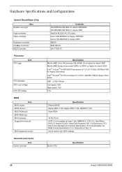
... 32 Pin PLCC ACPI 2.0 (if available, at 1.5 GHz, 400 MHz FSB for Aspire 3500 series SMT µ PGA 754 pin Low speed: 0.8V High speed: 1.5V 1.2V Specification Pheonix BIOS Aspire 3000 V1.00; Hardware Specifications and Configurations System Board Major Chip Item System core logic ... CPU core voltage CPU I/O voltage BIOS Item BIOS vendor BIOS Version BIOS ROM type BIOS ROM size BIOS package Supported protocols BIOS password control Second Level Cache Item Cache controller Controller SiS M760GX+SiS 963L for Aspire 3000/5000 SiS M661MX+SiS 963L for Aspire 3500 RealTek ALC203 AC 97 Codec built-...
... 32 Pin PLCC ACPI 2.0 (if available, at 1.5 GHz, 400 MHz FSB for Aspire 3500 series SMT µ PGA 754 pin Low speed: 0.8V High speed: 1.5V 1.2V Specification Pheonix BIOS Aspire 3000 V1.00; Hardware Specifications and Configurations System Board Major Chip Item System core logic ... CPU core voltage CPU I/O voltage BIOS Item BIOS vendor BIOS Version BIOS ROM type BIOS ROM size BIOS package Supported protocols BIOS password control Second Level Cache Item Cache controller Controller SiS M760GX+SiS 963L for Aspire 3000/5000 SiS M661MX+SiS 963L for Aspire 3500 RealTek ALC203 AC 97 Codec built-...
Aspire 3000 / 3500 / 5000 Service Guide
Page 35
... Item USB Compliancy Level OHCI Number of resolutions depends on the right side; NOTE: 16:9 aspect ratio monitors are limited by BIOS Setup PCMCIA Port Item PCMCIA controller Supports card type Number of the attached monitor. The complete list of USB port Location Serial ...memory size Chip voltage Supports ZV (Zoomed Video) port Graph interface Maximum resolution LCD Maximum resolution CRT Specification up to 128MB for Aspire 3000/5000 up to 64MB for Aspire 3500 Core / 2.5V, 1.5V, NO 4X AGP (Accelerated Graphic Port) Bus 1600X1200 (UXGA) 2048X1536@60HZ Video Resolutions Mode Monitor...
... Item USB Compliancy Level OHCI Number of resolutions depends on the right side; NOTE: 16:9 aspect ratio monitors are limited by BIOS Setup PCMCIA Port Item PCMCIA controller Supports card type Number of the attached monitor. The complete list of USB port Location Serial ...memory size Chip voltage Supports ZV (Zoomed Video) port Graph interface Maximum resolution LCD Maximum resolution CRT Specification up to 128MB for Aspire 3000/5000 up to 64MB for Aspire 3500 Core / 2.5V, 1.5V, NO 4X AGP (Accelerated Graphic Port) Bus 1600X1200 (UXGA) 2048X1536@60HZ Video Resolutions Mode Monitor...
Aspire 3000 / 3500 / 5000 Service Guide
Page 41
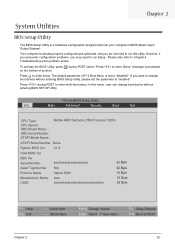
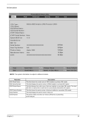
... on the bottom of F12 Boot Menu is a hardware configuration program built into your computer's BIOS (Basic Input/ Output System). Chapter 2 System Utilities BIOS Setup Utility The BIOS Setup Utility is set the parameter to "enabled". Please also refer to enter setup. In ...AMD Sempron (TM) Processor 2600+ ATAPI Serial Number None System BIOS Ver V1.0 VGA BIOS Ver KBC Ver Serial Number xxxxxxxxxxxxxxxxxxxxxx 22 Byte Asset Tag Number N/A 32 Byte Produce Name Aspire 3000 16 Byte Manufacturer Name: Acer UUID: xxxxxxxxxxxxxxxxxxxxxxxxxxxxxxxx 16 Byte 32 Byte F1 Help Esc Exit ...
... on the bottom of F12 Boot Menu is a hardware configuration program built into your computer's BIOS (Basic Input/ Output System). Chapter 2 System Utilities BIOS Setup Utility The BIOS Setup Utility is set the parameter to "enabled". Please also refer to enter setup. In ...AMD Sempron (TM) Processor 2600+ ATAPI Serial Number None System BIOS Ver V1.0 VGA BIOS Ver KBC Ver Serial Number xxxxxxxxxxxxxxxxxxxxxx 22 Byte Asset Tag Number N/A 32 Byte Produce Name Aspire 3000 16 Byte Manufacturer Name: Acer UUID: xxxxxxxxxxxxxxxxxxxxxxxxxxxxxxxx 16 Byte 32 Byte F1 Help Esc Exit ...
Aspire 3000 / 3500 / 5000 Service Guide
Page 42
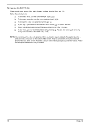
... to go to save any of the screen. T To change the value of a parameter if it is enclosed in any changes made and exit the BIOS Setup Utility. T Press ^ while you can change the value of the screen. T In any menu, you are shown on the bottom of a parameter, ... for a particular menu are in square brackets. NOTE: You can load default settings by pressing t. You can also press u to the Exit menu. Navigating the BIOS Utility There are found in models. 33 Chapter 2 Follow these instructions: T To choose a menu, use the cursor up/down keys ( wy). Read this carefully...
... to go to save any of the screen. T To change the value of a parameter if it is enclosed in any changes made and exit the BIOS Setup Utility. T Press ^ while you can change the value of the screen. T In any menu, you are shown on the bottom of a parameter, ... for a particular menu are in square brackets. NOTE: You can load default settings by pressing t. You can also press u to the Exit menu. Navigating the BIOS Utility There are found in models. 33 Chapter 2 Follow these instructions: T To choose a menu, use the cursor up/down keys ( wy). Read this carefully...
Aspire 3000 / 3500 / 5000 Service Guide
Page 43
... Model Name : Mobile AMD Sempron (TM) Processor 2600+ ATAPI Serial Number None System BIOS Ver V1.0 VGA BIOS Ver KBC Ver Serial Number Asset Tag Number Produce Name xxxxxxxxxxxxxxxxxxxxxx N/A Aspire 3000 22 Byte 32 Byte 16 Byte Manufacturer Name: Acer UUID: xxxxxxxxxxxxxxxxxxxxxxxxxxxxxxxx 16 Byte 32 Byte F1 Help Esc Exit ↑ ↓ Select Item...
... Model Name : Mobile AMD Sempron (TM) Processor 2600+ ATAPI Serial Number None System BIOS Ver V1.0 VGA BIOS Ver KBC Ver Serial Number Asset Tag Number Produce Name xxxxxxxxxxxxxxxxxxxxxx N/A Aspire 3000 22 Byte 32 Byte 16 Byte Manufacturer Name: Acer UUID: xxxxxxxxxxxxxxxxxxxxxxxxxxxxxxxx 16 Byte 32 Byte F1 Help Esc Exit ↑ ↓ Select Item...

Aspire 3000 / 3500 / 5000 Service Guide
Page 44
... Boot Exit System Time: System Date: System Memory: Extended Memory: Video Memory Quiet Boot: Power on display: Network boot F12 Boot Menu D2D Recovery USB BIOS Legacy Item Specific Help [15:56:48] [03/18/2005] , , or 640 KB selects field. Shows system base memory size 446MB Shows extended memory size...
... Boot Exit System Time: System Date: System Memory: Extended Memory: Video Memory Quiet Boot: Power on display: Network boot F12 Boot Menu D2D Recovery USB BIOS Legacy Item Specific Help [15:56:48] [03/18/2005] , , or 640 KB selects field. Shows system base memory size 446MB Shows extended memory size...

Aspire 3000 / 3500 / 5000 Service Guide
Page 45
... Enables, disables Boot Menu during POST. The function allows the user to create a hidden partition on display Network Boot F12 Boot Menu D2D Recovery USB BIOS Legacy Support Description Format/Option Sets the system time. Parameter System Time System Date System Memory Extended Memory VGA Memory Fast Boot Power on hard...
... Enables, disables Boot Menu during POST. The function allows the user to create a hidden partition on display Network Boot F12 Boot Menu D2D Recovery USB BIOS Legacy Support Description Format/Option Sets the system time. Parameter System Time System Date System Memory Extended Memory VGA Memory Fast Boot Power on hard...
Aspire 3000 / 3500 / 5000 Service Guide
Page 47
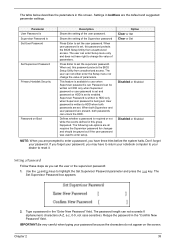
When set, this password protects the BIOS Setup Utility from unauthorized access. When both Supervisor and user password are present, both passwords are the default and suggested parameter settings. Don't forget your ... password because the characters do not appear on Boot Description Shows the setting of parameters. Type a password in boldface are set , this password protects the BIOS Setup Utility from unauthorized access. IMPORTANT:Be very careful when typing your password, you are all requires the Supervisor password for changes and should be...
When set, this password protects the BIOS Setup Utility from unauthorized access. When both Supervisor and user password are present, both passwords are the default and suggested parameter settings. Don't forget your ... password because the characters do not appear on Boot Description Shows the setting of parameters. Type a password in boldface are set , this password protects the BIOS Setup Utility from unauthorized access. IMPORTANT:Be very careful when typing your password, you are all requires the Supervisor password for changes and should be...
Aspire 3000 / 3500 / 5000 Service Guide
Page 48
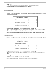
...parameter and press the e key. The Set Password box appears: 2. Press e. When you are done, press u to save the changes and exit the BIOS Setup Utility. If desired, you are done, press u to enable the Password on boot parameter. 6. When you can opt to save the changes and ...exit the BIOS Setup Utility. Changing a Password 1. Use the w and y keys to "Clear". 4. Type the current password in the Enter New Password field. The Set...
...parameter and press the e key. The Set Password box appears: 2. Press e. When you are done, press u to save the changes and exit the BIOS Setup Utility. If desired, you are done, press u to enable the Password on boot parameter. 6. When you can opt to save the changes and ...exit the BIOS Setup Utility. Changing a Password 1. Use the w and y keys to "Clear". 4. Type the current password in the Enter New Password field. The Set...

Aspire 3000 / 3500 / 5000 Service Guide
Page 52
... you use the AC adaptor power supply when you may not boot the system because the BIOS is required for the following conditions: T New versions of system programs T New features or options T Restore a BIOS when it becomes corrupted. NOTE: Please use the Phlash utility. If the battery pack does... not contain enough power to update the system BIOS flash ROM. Fellow the steps below to the bootable diskette. 3. Prepare a bootable diskette. 2. Copy the Phlash utilities to run the Phlash utility....
... you use the AC adaptor power supply when you may not boot the system because the BIOS is required for the following conditions: T New versions of system programs T New features or options T Restore a BIOS when it becomes corrupted. NOTE: Please use the Phlash utility. If the battery pack does... not contain enough power to update the system BIOS flash ROM. Fellow the steps below to the bootable diskette. 3. Prepare a bootable diskette. 2. Copy the Phlash utilities to run the Phlash utility....

Aspire 3000 / 3500 / 5000 Service Guide
Page 80
The following lists the error messages that the BIOS displays on page 83. Some of them display information about a hardware device, e.g., the amount of the error messages occur during POST. Others may indicate a problem ... actions in the sequence shown in FRU/Action column, if the FRU replacement does not solve the problem, put the original part back in the BIOS Setup Utility menus, reset the computer, enter Setup and install Setup defaults or correct the error. 71 Chapter 4 This index can also help you make...
The following lists the error messages that the BIOS displays on page 83. Some of them display information about a hardware device, e.g., the amount of the error messages occur during POST. Others may indicate a problem ... actions in the sequence shown in FRU/Action column, if the FRU replacement does not solve the problem, put the original part back in the BIOS Setup Utility menus, reset the computer, enter Setup and install Setup defaults or correct the error. 71 Chapter 4 This index can also help you make...
Aspire 3000 / 3500 / 5000 Service Guide
Page 81
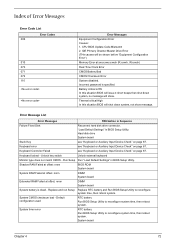
... system. Keyboard Controller Failed see "Keyboard or Auxiliary Input Device Check" on page 67. Battery critical LOW In this situation BIOS will shut down system, no message will be shown before "Equipment Configuration Error") Memory Error at offset: nnnn DIMM System board... System battery is specified. Error Message List Error Messages FRU/Action in BIOS Setup Utility. System CMOS checksum bad - "Load Default Settings" in Sequence Failure Fixed Disk Reconnect hard disk drive connector. Incorrect ...
... system. Keyboard Controller Failed see "Keyboard or Auxiliary Input Device Check" on page 67. Battery critical LOW In this situation BIOS will shut down system, no message will be shown before "Equipment Configuration Error") Memory Error at offset: nnnn DIMM System board... System battery is specified. Error Message List Error Messages FRU/Action in BIOS Setup Utility. System CMOS checksum bad - "Load Default Settings" in Sequence Failure Fixed Disk Reconnect hard disk drive connector. Incorrect ...

Aspire 3000 / 3500 / 5000 Service Guide
Page 82
... POST differed from CMOS Diskette drive A error Incorrect Drive A type - Check the drive is defined with the proper diskette type in BIOS Setup Utility System board System board DIMM System board DIMM System board DIMM System board Run "Load Default Settings" in Sequence RTC battery Run... time, then reboot system. Diskette drive Hard disk drive System board 73 Chapter 4 RTC battery System board Run "Load Default Settings" in BIOS Setup Utility. Error Message List Error Messages Real time clock error Previous boot incomplete - RTC battery System board Enter Setup and see if fixed...
... POST differed from CMOS Diskette drive A error Incorrect Drive A type - Check the drive is defined with the proper diskette type in BIOS Setup Utility System board System board DIMM System board DIMM System board DIMM System board Run "Load Default Settings" in Sequence RTC battery Run... time, then reboot system. Diskette drive Hard disk drive System board 73 Chapter 4 RTC battery System board Run "Load Default Settings" in BIOS Setup Utility. Error Message List Error Messages Real time clock error Previous boot incomplete - RTC battery System board Enter Setup and see if fixed...
Aspire 3000 / 3500 / 5000 Service Guide
Page 84
... Load alternate registers with initial POST values Restore CPU control word during warm boot Initialize PCI Bus Mastering devices Initialize keyboard controller BIOS ROM checksum Initialize cache before memory autosize 8254 timer initialization 8237 DMA controller initialization Reset Programmable Interrupt Controller Test DRAM refresh Test ... RAM failure on address line xxxx RAM failure on data bits xxxx of low byte of memory bus Enable cache before system BIOS shadow RAM failure on data bits xxxx of high byte of memory bus Test CPU bus-clock frequency Initialize Phoenix Dispatch Manager ...
... Load alternate registers with initial POST values Restore CPU control word during warm boot Initialize PCI Bus Mastering devices Initialize keyboard controller BIOS ROM checksum Initialize cache before memory autosize 8254 timer initialization 8237 DMA controller initialization Reset Programmable Interrupt Controller Test DRAM refresh Test ... RAM failure on address line xxxx RAM failure on data bits xxxx of low byte of memory bus Enable cache before system BIOS shadow RAM failure on data bits xxxx of high byte of memory bus Test CPU bus-clock frequency Initialize Phoenix Dispatch Manager ...


