Aspire 5050 / 3050 Service Guide
Page 8
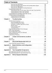
...Card/the Modem Board 66 Removing the ODD Module 67 Removing the LCD Module (including Keyboard 67 Disassembling the Main Uint 69 Separating the Main Unit into Upper Case and Lower Case Assembly 69 Disassembling the Upper Case Assembly 69 Disassembling the Lower Case Assembly 69 Disassembling the... View 95 Bottom View 96 Chapter 6 FRU (Field Replaceable Unit) List 99 Aspire 5050/3050 Exploded Diagram 100 Appendix A Model Definition and Configuration 112 Aspire 5050 Series 112 Aspire 3050 Series 134 Appendix B Test Compatible Components 139 Microsoft® Windows® XP Pro...
...Card/the Modem Board 66 Removing the ODD Module 67 Removing the LCD Module (including Keyboard 67 Disassembling the Main Uint 69 Separating the Main Unit into Upper Case and Lower Case Assembly 69 Disassembling the Upper Case Assembly 69 Disassembling the Lower Case Assembly 69 Disassembling the... View 95 Bottom View 96 Chapter 6 FRU (Field Replaceable Unit) List 99 Aspire 5050/3050 Exploded Diagram 100 Appendix A Model Definition and Configuration 112 Aspire 5050 Series 112 Aspire 3050 Series 134 Appendix B Test Compatible Components 139 Microsoft® Windows® XP Pro...
Aspire 5050 / 3050 Service Guide
Page 71
... rear side H*3 HDD Cover Wireless LAN Card O*4 HDD Module M*4 HDD Bracket HDD Lower Case *2 Speaker Set Lower Case Assembly O*2 Main Board Assembly RTC Battery Bluetooth Module Upper Case Assembly Microphone Upper Case Touchpad Assembly N*3 C*1 86.9A353.3R0*2 D*2 North Bridge Plate CPU Heatsink 86.9A353.3R0*2 O*2 Modem Board Fan Touchpad Bracket Touchpad CPU ODD Module G*2 ODD ODD Bracket Chapter 3 63 Start Battery...
... rear side H*3 HDD Cover Wireless LAN Card O*4 HDD Module M*4 HDD Bracket HDD Lower Case *2 Speaker Set Lower Case Assembly O*2 Main Board Assembly RTC Battery Bluetooth Module Upper Case Assembly Microphone Upper Case Touchpad Assembly N*3 C*1 86.9A353.3R0*2 D*2 North Bridge Plate CPU Heatsink 86.9A353.3R0*2 O*2 Modem Board Fan Touchpad Bracket Touchpad CPU ODD Module G*2 ODD ODD Bracket Chapter 3 63 Start Battery...
Aspire 5050 / 3050 Service Guide
Page 76
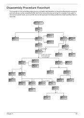
Take out the wireless LAN antenna set from the launch board. 6. Disconnect the LCD cable from the main board. . 9. Disconnect the lid switch cable from the main board. 8. Remove four screws holding the LCD module to the upper case. 5. Disconnect the microphone cable from the guide-line as shown. 10. If you laptop has CCD module (web camera module), please disconnect CCD cable as shown. 7. 4. Detach the entire LCD module. 68 Chapter 3 Remove the two screw fastening the keyboard to the upper and lower case assembly. 11.
Take out the wireless LAN antenna set from the launch board. 6. Disconnect the LCD cable from the main board. . 9. Disconnect the lid switch cable from the main board. 8. Remove four screws holding the LCD module to the upper case. 5. Disconnect the microphone cable from the guide-line as shown. 10. If you laptop has CCD module (web camera module), please disconnect CCD cable as shown. 7. 4. Detach the entire LCD module. 68 Chapter 3 Remove the two screw fastening the keyboard to the upper and lower case assembly. 11.
Aspire 5050 / 3050 Service Guide
Page 77
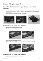
... upper case. 4. Disassembling the Main Uint Separating the Main Unit into Upper Case and Lower Case Assembly 1. Remove three screws fastening the upper case assembly and the lower case assembly. 2. Disassembling the Upper Case Assembly 1. Take out the media board from the upper case. 3. Disassembling the Lower Case Assembly 1. M2.0L1.7x1) holding the upper assembly and the lower case assembly on the bottom. 3. Detach the upper case assembly from the main board...
... upper case. 4. Disassembling the Main Uint Separating the Main Unit into Upper Case and Lower Case Assembly 1. Remove three screws fastening the upper case assembly and the lower case assembly. 2. Disassembling the Upper Case Assembly 1. Take out the media board from the upper case. 3. Disassembling the Lower Case Assembly 1. M2.0L1.7x1) holding the upper assembly and the lower case assembly on the bottom. 3. Detach the upper case assembly from the main board...


