Acer Aspire 1640 Service Guide
Page 12
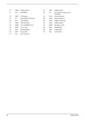
21 CN20 USB Connector 23 U19 BIOS ROM 25 CN22 RTC Battery 27 U1 LAN Chipset RTL8100CL 29 U18 South Bridge 31 CN25 HDD Connector 33 CN28 Line-out/SPEDIF Jack 35 CN30 Line-in Jack 37 SW2 Bluetooth Button 39 LED1 Power LED 41 U10 Fan Connector 22 CN21 USB Connector 24 U4 EC PC97551 (Power and I/O Connector) 26 CN18 Memory Socket 1 28 CN19 Memory Socket 2 30 CN24 PCMCIA Connector 32 CN27 USB Connector 34 CN29 Microphone Jack 36 SW3 WLAN Button 38 LED2 Charger LED 40 U22 Audio Codec 6 Aspire 1640
21 CN20 USB Connector 23 U19 BIOS ROM 25 CN22 RTC Battery 27 U1 LAN Chipset RTL8100CL 29 U18 South Bridge 31 CN25 HDD Connector 33 CN28 Line-out/SPEDIF Jack 35 CN30 Line-in Jack 37 SW2 Bluetooth Button 39 LED1 Power LED 41 U10 Fan Connector 22 CN21 USB Connector 24 U4 EC PC97551 (Power and I/O Connector) 26 CN18 Memory Socket 1 28 CN19 Memory Socket 2 30 CN24 PCMCIA Connector 32 CN27 USB Connector 34 CN29 Microphone Jack 36 SW3 WLAN Button 38 LED2 Charger LED 40 U22 Audio Codec 6 Aspire 1640
Acer Aspire 1640 Service Guide
Page 16
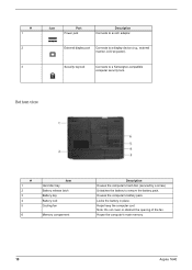
... monitor, LCD projector). Note: Do not cover or obstruct the opening of the fan. External display port Connects to a Kensington-compatible computer security lock. House the computer's main memory. 10 Aspire 1640 Houses the computer's battery pack. Bottom view # 1 2 3 4 5 6... Item Hard disc bay Battery release latch Battery bay Battery lock Cooling fan Memory comparment Description Houses the computer's hard disc (secured by a...
... monitor, LCD projector). Note: Do not cover or obstruct the opening of the fan. External display port Connects to a Kensington-compatible computer security lock. House the computer's main memory. 10 Aspire 1640 Houses the computer's battery pack. Bottom view # 1 2 3 4 5 6... Item Hard disc bay Battery release latch Battery bay Battery lock Cooling fan Memory comparment Description Houses the computer's hard disc (secured by a...

Acer Aspire 1640 Service Guide
Page 56
Disconnect the fan cable. Use a flat-bladed screwdriver to assemble the thermal module, fasten the screws as the order 1, 2, 3 on the thermal module. Remove the CPU from the ... order 3, 2, 1 on the thermal module. 6. Remove the three screws holding the thermal door 2. Detach the thermal door. 3. Removing the Thermal Module and CPU 1. Disconnect the fan cable from the socket carefully. NOTE: When you need to release the CPU lock. 7. .
Disconnect the fan cable. Use a flat-bladed screwdriver to assemble the thermal module, fasten the screws as the order 1, 2, 3 on the thermal module. Remove the CPU from the ... order 3, 2, 1 on the thermal module. 6. Remove the three screws holding the thermal door 2. Detach the thermal door. 3. Removing the Thermal Module and CPU 1. Disconnect the fan cable from the socket carefully. NOTE: When you need to release the CPU lock. 7. .
Aspire 1640 User's Guide
Page 15
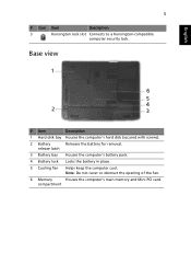
release latch 3 Battery bay Houses the computer's battery pack. 4 Battery lock Locks the battery in place. 5 Cooling fan Helps keep the computer cool. Note: Do not cover or obstruct the opening of the fan. 6 Memory Houses the computer's main memory and Mini PCI card. English 5 # Icon Item Description 3 Kensington lock slot Connects to a Kensington-compatible computer security lock. compartment Base view 1 6 5 4 2 3 # Item Description 1 Hard disk bay Houses the computer's hard disk (secured with screws). 2 Battery Releases the battery for removal.
release latch 3 Battery bay Houses the computer's battery pack. 4 Battery lock Locks the battery in place. 5 Cooling fan Helps keep the computer cool. Note: Do not cover or obstruct the opening of the fan. 6 Memory Houses the computer's main memory and Mini PCI card. English 5 # Icon Item Description 3 Kensington lock slot Connects to a Kensington-compatible computer security lock. compartment Base view 1 6 5 4 2 3 # Item Description 1 Hard disk bay Houses the computer's hard disk (secured with screws). 2 Battery Releases the battery for removal.


