
Aspire 1500 Service Guide
Page 7
...BIOS Flash Utility 41 Chapter 3 Machine Disassembly and Replacement 42 General Information 43 Before You Begin 43 Disassembly Procedure Flowchart 44 Removing the Battery 46 Removing the Memory Module 47 Removing the Modem Board 48 Removing the Hard Disk Drive Module 49 Removing the LCD Module 50 Disassembling...LCD Module 81 Installing the Hard Disk Drive Module 84 Installing the Modem Board 85 Installing the Memory Module 86 Installing the Battery 87 Chapter 4 Troubleshooting 88 System Check Procedures 89 External Diskette Drive Check 89 External CD-ROM Drive Check 89 VII
...BIOS Flash Utility 41 Chapter 3 Machine Disassembly and Replacement 42 General Information 43 Before You Begin 43 Disassembly Procedure Flowchart 44 Removing the Battery 46 Removing the Memory Module 47 Removing the Modem Board 48 Removing the Hard Disk Drive Module 49 Removing the LCD Module 50 Disassembling...LCD Module 81 Installing the Hard Disk Drive Module 84 Installing the Modem Board 85 Installing the Memory Module 86 Installing the Battery 87 Chapter 4 Troubleshooting 88 System Check Procedures 89 External Diskette Drive Check 89 External CD-ROM Drive Check 89 VII
Aspire 1500 Service Guide
Page 13
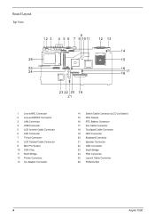
Board Layout Top View 1 Line-in/MIC Connector 2 Line-out/S/PDIF Connector 3 LAN Connector 4 USB Connector 5 LCD Inverter Cable Connector 6 CRT Connector 7 TV-out Connector 8 LCD Coaxial Cable Connector 9 Mini PCI Socket 10 VGA Chip 11 North Bridge 12 Printer Connector 13 AC Adapter Connector 14 Switch Cable Connector (LCD Lid Switch) 15 CPU Socket 16 RTC Battery Connector 17 Fan Cable Connector 18 Touchpad Cable Connector 19 HDD Connector 20 Keyboard Connector 21 Speaker Connector 22 ODD Connector 23 South Bridge 24 FDD Connector 25 Launch Cable Connector 26 PCMCIA Slot 4 Aspire 1500
Board Layout Top View 1 Line-in/MIC Connector 2 Line-out/S/PDIF Connector 3 LAN Connector 4 USB Connector 5 LCD Inverter Cable Connector 6 CRT Connector 7 TV-out Connector 8 LCD Coaxial Cable Connector 9 Mini PCI Socket 10 VGA Chip 11 North Bridge 12 Printer Connector 13 AC Adapter Connector 14 Switch Cable Connector (LCD Lid Switch) 15 CPU Socket 16 RTC Battery Connector 17 Fan Cable Connector 18 Touchpad Cable Connector 19 HDD Connector 20 Keyboard Connector 21 Speaker Connector 22 ODD Connector 23 South Bridge 24 FDD Connector 25 Launch Cable Connector 26 PCMCIA Slot 4 Aspire 1500

Aspire 1500 Service Guide
Page 19
Houses the computer's main memory. 10 Aspire 1500 Unlatches the battery to remove the battery pack. Bottom Panel # 1 2 3 Item Battery bay Battery release latch Memory compartment Description Houses the computer's battery pack.
Houses the computer's main memory. 10 Aspire 1500 Unlatches the battery to remove the battery pack. Bottom Panel # 1 2 3 Item Battery bay Battery release latch Memory compartment Description Houses the computer's battery pack.

Aspire 1500 Service Guide
Page 20
... when it enters into or resumes from hibernation mode. 4 Media Activity Lights when the floppy drive, hard disk or optical drive is active. 5 Battery Charge Lights when the battery is being charged. 6 Caps Lock Lights when Caps Lock is activated. 7 Num Lock Lights when Numeric Lock is activated. (Fn-F11) Chapter 1 11...
... when it enters into or resumes from hibernation mode. 4 Media Activity Lights when the floppy drive, hard disk or optical drive is active. 5 Battery Charge Lights when the battery is being charged. 6 Caps Lock Lights when Caps Lock is activated. 7 Num Lock Lights when Numeric Lock is activated. (Fn-F11) Chapter 1 11...
Aspire 1500 Service Guide
Page 32
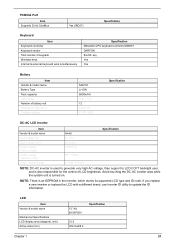
... 32 bit CardBus Yes (IRQ17) Specification Keyboard Item Keyboard controller Keyboard vendor Total number of LCD brightness. key Yes Yes Battery Item Vendor & model name Battery Type Pack capacity Cell voltage Number of battery cell Package configuration Package voltage SANYO Li-ION 6600mAH 3.8V / 1.2V 12 4529 / 8S 41.8V / 9.6V Specification DC...
... 32 bit CardBus Yes (IRQ17) Specification Keyboard Item Keyboard controller Keyboard vendor Total number of LCD brightness. key Yes Yes Battery Item Vendor & model name Battery Type Pack capacity Cell voltage Number of battery cell Package configuration Package voltage SANYO Li-ION 6600mAH 3.8V / 1.2V 12 4529 / 8S 41.8V / 9.6V Specification DC...
Aspire 1500 Service Guide
Page 35
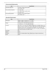
...(W) x 290(D) x 38.6(H)mm for 14.1" Model 326(W) x 290(D) x 42.9(H)mm for 15.0" Model 7.32 Ibs for 14.1" TFT LCD model with battery 7.51 Ibs for 15.0" TFT LCD model with battery Two Type II or one Type III PC CardBus (PCMCIA) slot, one IEEE 1394 port, one FIR port, one RJ-11..., one external monitor port, one microphone-in jack (3.5mm mini jack), one headphone jack (3.5mm mini jack), four USB 2.0 ports One Plastic Power-on, Standby, Battery Status, Media Access, CapsLock and NumLock Power 26 Aspire 1500
...(W) x 290(D) x 38.6(H)mm for 14.1" Model 326(W) x 290(D) x 42.9(H)mm for 15.0" Model 7.32 Ibs for 14.1" TFT LCD model with battery 7.51 Ibs for 15.0" TFT LCD model with battery Two Type II or one Type III PC CardBus (PCMCIA) slot, one IEEE 1394 port, one FIR port, one RJ-11..., one external monitor port, one microphone-in jack (3.5mm mini jack), one headphone jack (3.5mm mini jack), four USB 2.0 ports One Plastic Power-on, Standby, Battery Status, Media Access, CapsLock and NumLock Power 26 Aspire 1500

Aspire 1500 Service Guide
Page 50
... the steps below to finish BIOS flash, you run the Phlash. 1. BIOS Flash Utility The BIOS flash memory update is not completely loaded. If the battery pack does not contain enough power to run the Phlash utility. The Phlash utility has auto-execution function. 41 Chapter 2
... the steps below to finish BIOS flash, you run the Phlash. 1. BIOS Flash Utility The BIOS flash memory update is not completely loaded. If the battery pack does not contain enough power to run the Phlash utility. The Phlash utility has auto-execution function. 41 Chapter 2
Aspire 1500 Service Guide
Page 53
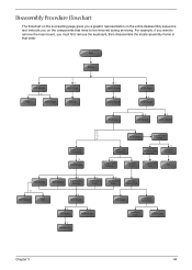
... keyboard, then disassemble the inside assembly frame in that need to remove the main board, you on the components that order. Start Battery HDD Module *2 HDD HDD Holder *2 Dimm Cover Memory *1 Modem Cover *2 Modem Board Hinge Caps *2 Middle Cover Keyboard *6 LCD... Module *2 Launch Board Lower Case Assembly *2 FDD Module *3 *3 *11 *4 RTC Battery *3 Mini PCI Card Plate Upper Case Assembly Disconnect Wireless LAN Antenna *4 Thermal Module *4 Wireless LAN Antenna Touchpad Cover Wireless LAN Card CPU ODD Module...
... keyboard, then disassemble the inside assembly frame in that need to remove the main board, you on the components that order. Start Battery HDD Module *2 HDD HDD Holder *2 Dimm Cover Memory *1 Modem Cover *2 Modem Board Hinge Caps *2 Middle Cover Keyboard *6 LCD... Module *2 Launch Board Lower Case Assembly *2 FDD Module *3 *3 *11 *4 RTC Battery *3 Mini PCI Card Plate Upper Case Assembly Disconnect Wireless LAN Antenna *4 Thermal Module *4 Wireless LAN Antenna Touchpad Cover Wireless LAN Card CPU ODD Module...

Aspire 1500 Service Guide
Page 55
Then slide the battery out from the machine. To remove the battery, push the battery release latch. 2. Removing the Battery 1. Chapter 3 46
Then slide the battery out from the machine. To remove the battery, push the battery release latch. 2. Removing the Battery 1. Chapter 3 46

Aspire 1500 Service Guide
Page 56
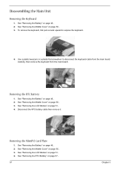
Then remove the memory. 47 Chapter 3 To remove the memory module from the machine, first remove the two screws holding the dimm cover. 3. Pop up the memory. 5. See "Removing the Battery" on page 46.. 2. Remove the dimm cover. 4. Removing the Memory Module 1.
Then remove the memory. 47 Chapter 3 To remove the memory module from the machine, first remove the two screws holding the dimm cover. 3. Pop up the memory. 5. See "Removing the Battery" on page 46.. 2. Remove the dimm cover. 4. Removing the Memory Module 1.

Aspire 1500 Service Guide
Page 57
Then remove the modem board from the modem board as shown. See "Removing the Battery" on the picture indicate. 5. Chapter 3 48 Remove two screws from the main unit carefully by using a plastic bladed screw driver. 6. Please remove the screws according to the number on page 46. 2. Disconnect the modem cable from the modem cover. 3. To remove the modem board, first remove the screw from the modem board, then remove the modem board. Remove the modem cover from the machine. 4. Removing the Modem Board 1.
Then remove the modem board from the modem board as shown. See "Removing the Battery" on the picture indicate. 5. Chapter 3 48 Remove two screws from the main unit carefully by using a plastic bladed screw driver. 6. Please remove the screws according to the number on page 46. 2. Disconnect the modem cable from the modem cover. 3. To remove the modem board, first remove the screw from the modem board, then remove the modem board. Remove the modem cover from the machine. 4. Removing the Modem Board 1.

Aspire 1500 Service Guide
Page 58
Then take the hard disk drive out of the main unit. Remove the two screws that fasten the HDD holder. 4. Disassembling the Hard Disk Drive Module 1. To remove the hard disk drive, pull the hard disk dirve carefully. 3. See "Removing the Hard Disk Drive Module" on page 46.. 2. See "Removing the Battery" on page 49.. 3. See "Removing the Battery" on page 46.. 2. Detach the hard disk drive from the HDD holder. 49 Chapter 3 Removing the Hard Disk Drive Module 1.
Then take the hard disk drive out of the main unit. Remove the two screws that fasten the HDD holder. 4. Disassembling the Hard Disk Drive Module 1. To remove the hard disk drive, pull the hard disk dirve carefully. 3. See "Removing the Hard Disk Drive Module" on page 46.. 2. See "Removing the Battery" on page 49.. 3. See "Removing the Battery" on page 46.. 2. Detach the hard disk drive from the HDD holder. 49 Chapter 3 Removing the Hard Disk Drive Module 1.

Aspire 1500 Service Guide
Page 59
Remove the left hinge cap. 5. Remove the screw that secures the middle cover. 4. Disconnect the launch board cable then remove the middle cover off the main unit. . Detach the middle cover from the machine. 7. Chapter 3 50 Removing the Launch Board 1. See "Removing the Battery" on the other side. 6. Then remove the screw holding the middle cover on page 46.. To remove the middle cover, first use a plastic flat screwdriver to remove the right hinge cap. 3. Removing the LCD Module Removing the Middle Cover 1. See "Removing the Battery" on page 46.. 2.
Remove the left hinge cap. 5. Remove the screw that secures the middle cover. 4. Disconnect the launch board cable then remove the middle cover off the main unit. . Detach the middle cover from the machine. 7. Chapter 3 50 Removing the Launch Board 1. See "Removing the Battery" on the other side. 6. Then remove the screw holding the middle cover on page 46.. To remove the middle cover, first use a plastic flat screwdriver to remove the right hinge cap. 3. Removing the LCD Module Removing the Middle Cover 1. See "Removing the Battery" on page 46.. 2.

Aspire 1500 Service Guide
Page 60
... the Middle Cover" on page 46.. 2. Remove the two screws and then detach the launch board from the main unit. 51 Chapter 3 See "Removing the Battery" on page 50.. 3.
... the Middle Cover" on page 46.. 2. Remove the two screws and then detach the launch board from the main unit. 51 Chapter 3 See "Removing the Battery" on page 50.. 3.

Aspire 1500 Service Guide
Page 62
... the Middle Cover" on page 50.. 4. See "Removing the Launch Board" on page 50.. 3. See "Removing the LCD Module" on page 46.. 2. See "Removing the Battery" on page 51.. 5. See "Removing the Middle Cover" on page 50.. 4. See "Removing the Launch Board" on page 50.. 3. See "Removing the LCD Bezel" on... remove the four screw pads, and then remove the four screws that fasten the LCD bezel. 6. Removing the Inverter Board (15" LCD) 1. See "Removing the Battery" on page 53.. 6. See "Removing the LCD Module" on page 51.. 5.
... the Middle Cover" on page 50.. 4. See "Removing the Launch Board" on page 50.. 3. See "Removing the LCD Module" on page 46.. 2. See "Removing the Battery" on page 51.. 5. See "Removing the Middle Cover" on page 50.. 4. See "Removing the Launch Board" on page 50.. 3. See "Removing the LCD Bezel" on... remove the four screw pads, and then remove the four screws that fasten the LCD bezel. 6. Removing the Inverter Board (15" LCD) 1. See "Removing the Battery" on page 53.. 6. See "Removing the LCD Module" on page 51.. 5.

Aspire 1500 Service Guide
Page 63
... the LCD panel as the picture below shows when you reassemble the LCD module. See "Removing the Launch Board" on page 53. 6. See "Removing the Battery" on page 51.. 5. See "Removing the LCD Module" on page 46.. 2.
... the LCD panel as the picture below shows when you reassemble the LCD module. See "Removing the Launch Board" on page 53. 6. See "Removing the Battery" on page 51.. 5. See "Removing the LCD Module" on page 46.. 2.

Aspire 1500 Service Guide
Page 64
..... 2. See "Removing the Inverter Board (15" LCD)" on page 53.. 6. See "Removing the LCD Bezel" on page 53.. 7. Removing the LCD Brackets 1. See "Removing the Battery" on page 50.. 3. See "Removing the Middle Cover" on page 46.. 2. See "Removing the Launch Board" on page 54.. 8. Remove the four screws holding the...
..... 2. See "Removing the Inverter Board (15" LCD)" on page 53.. 6. See "Removing the LCD Bezel" on page 53.. 7. Removing the LCD Brackets 1. See "Removing the Battery" on page 50.. 3. See "Removing the Middle Cover" on page 46.. 2. See "Removing the Launch Board" on page 54.. 8. Remove the four screws holding the...

Aspire 1500 Service Guide
Page 65
See "Removing the Battery" on page 53.. 6. See "Removing the LCD Bezel" on page 46.. 2. Remove the screw holding the right hinge, then remove the right hinge. 9. See "Removing the Middle Cover" on page 54.. 8. See "Removing the 15" TFT LCD" on page 50.. 3. Chapter 3 56 Remove the screw holding the left hinge, then remove the left hinge. Removing the LCD Hinges 1. See "Removing the Launch Board" on page 51.. 5. See "Removing the LCD Module" on page 50.. 4. See "Removing the Inverter Board (15" LCD)" on page 53.. 7.
See "Removing the Battery" on page 53.. 6. See "Removing the LCD Bezel" on page 46.. 2. Remove the screw holding the right hinge, then remove the right hinge. 9. See "Removing the Middle Cover" on page 54.. 8. See "Removing the 15" TFT LCD" on page 50.. 3. Chapter 3 56 Remove the screw holding the left hinge, then remove the left hinge. Removing the LCD Hinges 1. See "Removing the Launch Board" on page 51.. 5. See "Removing the LCD Module" on page 50.. 4. See "Removing the Inverter Board (15" LCD)" on page 53.. 7.
Aspire 1500 Service Guide
Page 66
... board. See "Removing the Middle Cover" on page 46.. 2. See "Removing the Battery" on page 50.. 3. Disconnect the RTC battery cable then remove it. Removing the RTC Battery 1. See "Removing the RTC Battery" on page 50.. 3. See "Removing the Middle Cover" on page 57.. 57 ... "Removing the LCD Module" on page 50.. 3. Use a plastic tweezers or a plastic flat screwdriver to expose the keyboard. 4. See "Removing the Battery" on page 51.. 4. Removing the MimiPCI Card Plate 1. See "Removing the LCD Module" on page 46.. 2. Disassembling the Main Unit Removing the Keyboard...
... board. See "Removing the Middle Cover" on page 46.. 2. See "Removing the Battery" on page 50.. 3. Disconnect the RTC battery cable then remove it. Removing the RTC Battery 1. See "Removing the RTC Battery" on page 50.. 3. See "Removing the Middle Cover" on page 57.. 57 ... "Removing the LCD Module" on page 50.. 3. Use a plastic tweezers or a plastic flat screwdriver to expose the keyboard. 4. See "Removing the Battery" on page 51.. 4. Removing the MimiPCI Card Plate 1. See "Removing the LCD Module" on page 46.. 2. Disassembling the Main Unit Removing the Keyboard...
Aspire 1500 Service Guide
Page 67
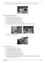
... three screws holding the mini PCI card plate and remove the mini PCI card plate. Then remove the thermal module. See "Removing the RTC Battery" on page 51.. 4. Disconnect the fan cable then remove the four screws fastening the thermal module. 7. Remember to press down the lever...57.. 5. Lift up the CPU socket lever. See "Removing the MimiPCI Card Plate" on page 46.. 2. Removing the Thermal Module 1. See "Removing the Battery" on page 57.. 6. See "Removing the Middle Cover" on page 57.. 6. See "Removing the MimiPCI Card Plate" on page 50.. 3. See "Removing the...
... three screws holding the mini PCI card plate and remove the mini PCI card plate. Then remove the thermal module. See "Removing the RTC Battery" on page 51.. 4. Disconnect the fan cable then remove the four screws fastening the thermal module. 7. Remember to press down the lever...57.. 5. Lift up the CPU socket lever. See "Removing the MimiPCI Card Plate" on page 46.. 2. Removing the Thermal Module 1. See "Removing the Battery" on page 57.. 6. See "Removing the Middle Cover" on page 57.. 6. See "Removing the MimiPCI Card Plate" on page 50.. 3. See "Removing the...


