
Aspire 1500 Service Guide
Page 7
... Keyboard 13 Special keys 13 Hot Keys 15 Hardware Specifications and Configurations 18 Chapter 2 System Utilities 28 BIOS Setup Utility 28 Navigating the BIOS Utility 29 Information 30 Main 31 Advanced 33 Security 35 Boot 39 Exit 40 BIOS Flash Utility 41 Chapter 3 Machine Disassembly and Replacement 42 General Information 43 Before You Begin 43 Disassembly Procedure Flowchart 44 Removing the Battery 46 Removing the Memory Module 47 Removing the Modem Board 48 Removing the Hard Disk Drive Module 49 Removing the LCD Module 50 Disassembling...
... Keyboard 13 Special keys 13 Hot Keys 15 Hardware Specifications and Configurations 18 Chapter 2 System Utilities 28 BIOS Setup Utility 28 Navigating the BIOS Utility 29 Information 30 Main 31 Advanced 33 Security 35 Boot 39 Exit 40 BIOS Flash Utility 41 Chapter 3 Machine Disassembly and Replacement 42 General Information 43 Before You Begin 43 Disassembly Procedure Flowchart 44 Removing the Battery 46 Removing the Memory Module 47 Removing the Modem Board 48 Removing the Hard Disk Drive Module 49 Removing the LCD Module 50 Disassembling...
Aspire 1500 Service Guide
Page 15
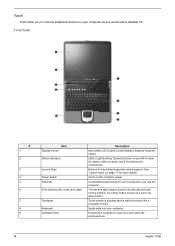
... data into your computer. Front Panel # 1 2 3 4 5 6 7 8 9 Item Display screen Status indicators Launch Keys Power switch Palmrest Click buttons (left and right mouse buttons, the center button serves as you use . 6 Aspire 1500 Comfortable support area for more details. Touch-sensitive pointing device which functions like the left , center and right) Touchpad Keyboard Ventilation Slot Description Also called LCD (Liquid Crystal Display), displays computer output. Buttons for launching frequently used programs. See "Launch keys" on page 17 for...
... data into your computer. Front Panel # 1 2 3 4 5 6 7 8 9 Item Display screen Status indicators Launch Keys Power switch Palmrest Click buttons (left and right mouse buttons, the center button serves as you use . 6 Aspire 1500 Comfortable support area for more details. Touch-sensitive pointing device which functions like the left , center and right) Touchpad Keyboard Ventilation Slot Description Also called LCD (Liquid Crystal Display), displays computer output. Buttons for launching frequently used programs. See "Launch keys" on page 17 for...

Aspire 1500 Service Guide
Page 24
... the display screen and external monitor. Turns the display screen backlight off . Turns the internal touchpad on and off Switches display output between the power management scheme used by the computer (function available if supported by operating system). Fn-y Volume down Decreases the sound volume. Fn-x Brightness up Increases the sound volume. Hot Key Fn-l Fn-m Fn-n Fn-o Fn-p Fn-q Fn-r Fn-s Fn-w Icon Function Hotkey help Setup Description Displays a list of the computer's controls like screen contrast and brightness, volume output and the BIOS Utility. Puts...
... the display screen and external monitor. Turns the display screen backlight off . Turns the internal touchpad on and off Switches display output between the power management scheme used by the computer (function available if supported by operating system). Fn-y Volume down Decreases the sound volume. Fn-x Brightness up Increases the sound volume. Hot Key Fn-l Fn-m Fn-n Fn-o Fn-p Fn-q Fn-r Fn-s Fn-w Icon Function Hotkey help Setup Description Displays a list of the computer's controls like screen contrast and brightness, volume output and the BIOS Utility. Puts...
Aspire 1500 Service Guide
Page 27
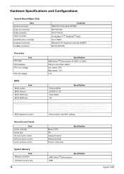
... High speed: 1.5V 1.2V BIOS Item BIOS vendor BIOS Version BIOS ROM type BIOS ROM size BIOS package Supported protocols BIOS password control Specification Phoenix BIOS AS1500 V1.00 Flash ROM 1M 32 Pin PLCC ACPI 2.0 (if available, at least 1.0b), SMBIOS 2.3, PCI 2.2, Boot Block, PXE 2.0, Mobile PC2001, Hard Disk Password, INT 13h Extensions, PCI Bus Power Management interface Specification, EI Torito-Bootable CDROM Format Specification V1.0, Simple Boot Flag 1.0 Set by switch, see SW1 settings Second Level Cache Item...
... High speed: 1.5V 1.2V BIOS Item BIOS vendor BIOS Version BIOS ROM type BIOS ROM size BIOS package Supported protocols BIOS password control Specification Phoenix BIOS AS1500 V1.00 Flash ROM 1M 32 Pin PLCC ACPI 2.0 (if available, at least 1.0b), SMBIOS 2.3, PCI 2.2, Boot Block, PXE 2.0, Mobile PC2001, Hard Disk Password, INT 13h Extensions, PCI Bus Power Management interface Specification, EI Torito-Bootable CDROM Format Specification V1.0, Simple Boot Flag 1.0 Set by switch, see SW1 settings Second Level Cache Item...

Aspire 1500 Service Guide
Page 28
... table lists some system memory configurations. System Memory Item DIMM socket number Supports memory size per socket Supports maximum memory size Supports DIMM type Supports DIMM Speed Supports DIMM voltage Supports DIMM package Memory module combinations Specification 2 Sockets 128MB 2048MB DDR-DRAM 333 MHz 2.5 V/1.25V 200-pin so-DIMM You can install memory modules in any combinations as long as they match the above specifications . LAN Interface Item Chipset Supports LAN protocol LAN connector type LAN connector location Specification...
... table lists some system memory configurations. System Memory Item DIMM socket number Supports memory size per socket Supports maximum memory size Supports DIMM type Supports DIMM Speed Supports DIMM voltage Supports DIMM package Memory module combinations Specification 2 Sockets 128MB 2048MB DDR-DRAM 333 MHz 2.5 V/1.25V 200-pin so-DIMM You can install memory modules in any combinations as long as they match the above specifications . LAN Interface Item Chipset Supports LAN protocol LAN connector type LAN connector location Specification...
Aspire 1500 Service Guide
Page 32
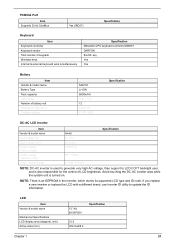
... backlight user, and is used to generate very high AC voltage, then support to update the ID information. . Avoid touching the DC-AC inverter area while the system unit is an EEPROM in the inverter, which stores its supported LCD type and ID code. PCMCIA Port Item Supports 32 bit CardBus Yes (IRQ17) Specification Keyboard Item Keyboard controller Keyboard vendor Total number of LCD brightness. LCD Item Vendor & model name Mechanical Specifications LCD display...
... backlight user, and is used to generate very high AC voltage, then support to update the ID information. . Avoid touching the DC-AC inverter area while the system unit is an EEPROM in the inverter, which stores its supported LCD type and ID code. PCMCIA Port Item Supports 32 bit CardBus Yes (IRQ17) Specification Keyboard Item Keyboard controller Keyboard vendor Total number of LCD brightness. LCD Item Vendor & model name Mechanical Specifications LCD display...
Aspire 1500 Service Guide
Page 41
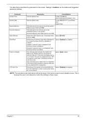
... the device control is disabled. The table below describes the parameters in boldface are the default and suggested parameter settings. Settings in this screen. Parameter System Time System Date System Memory Extended Memory Video Memory Quiet Boot Power on display LCD Auto Dim Description Format/Option Sets the system time. Enabled: Customer Logo is displayed, and Summary Screen is set to 32MB Determines if Customer Logo will automatically dim Option: Enabled or Disabled the LCD brightness in order...
... the device control is disabled. The table below describes the parameters in boldface are the default and suggested parameter settings. Settings in this screen. Parameter System Time System Date System Memory Extended Memory Video Memory Quiet Boot Power on display LCD Auto Dim Description Format/Option Sets the system time. Enabled: Customer Logo is displayed, and Summary Screen is set to 32MB Determines if Customer Logo will automatically dim Option: Enabled or Disabled the LCD brightness in order...
Aspire 1500 Service Guide
Page 44
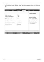
... help safeguard and protect your computer from unauthorized use. F1 Help Esc Exit ↑ ↓ Select Item ← → Select Menu F5/F6 Change Values Enter Select 4 Sub-Menu F9 Setup Defaults F10 Save and Exit 35 Chapter 2 It can be used to boot up when Password on boot is Set User Password Set Supervisor Password Primary HardDisk Security Password on Boot Clear Clear [Enter] [Enter] [Disabled] [Disabled] Item Specific Help Supervisor Password controls accesses of the whole setup utility.
... help safeguard and protect your computer from unauthorized use. F1 Help Esc Exit ↑ ↓ Select Item ← → Select Menu F5/F6 Change Values Enter Select 4 Sub-Menu F9 Setup Defaults F10 Save and Exit 35 Chapter 2 It can be used to boot up when Password on boot is Set User Password Set Supervisor Password Primary HardDisk Security Password on Boot Clear Clear [Enter] [Enter] [Disabled] [Disabled] Item Specific Help Supervisor Password controls accesses of the whole setup utility.
Aspire 1500 Service Guide
Page 45
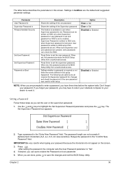
... changes and exit the BIOS Setup Utility. Option Clear or Set Clear or Set Disabled or Enabled Disabled or Enabled NOTE: When you are done, press u to set . Use the w andy keys to "Set". 4. When you are prompted to enabled. Password can not exceeds 8 alphanumeric characters (A-Z, a-z, 0-9, not case sensitive). When set to enter a password, you can unlock the HDD. Type a password in this password protects the BIOS Setup Utility from unauthorized access. IMPORTANT:Be very careful when typing your password, you set , this screen. Supervisor Password...
... changes and exit the BIOS Setup Utility. Option Clear or Set Clear or Set Disabled or Enabled Disabled or Enabled NOTE: When you are done, press u to set . Use the w andy keys to "Set". 4. When you are prompted to enabled. Password can not exceeds 8 alphanumeric characters (A-Z, a-z, 0-9, not case sensitive). When set to enter a password, you can unlock the HDD. Type a password in this password protects the BIOS Setup Utility from unauthorized access. IMPORTANT:Be very careful when typing your password, you set , this screen. Supervisor Password...

Aspire 1500 Service Guide
Page 46
... without typing anything in the Confirm New Password field. 4. If desired, you have changed the settings, press u to save the changes and exit the BIOS Setup Utility. Changing a Password 1. After setting the password, the computer sets the User Password parameter to highlight the Set Supervisor Password parameter and press the e key. Press e. Type the current password in the Enter Current Password field and press e. 3. Use the w and y keys to "Set". 5. When you can enable the Password on boot parameter...
... without typing anything in the Confirm New Password field. 4. If desired, you have changed the settings, press u to save the changes and exit the BIOS Setup Utility. Changing a Password 1. After setting the password, the computer sets the User Password parameter to highlight the Set Supervisor Password parameter and press the e key. Press e. Type the current password in the Enter Current Password field and press e. 3. Use the w and y keys to "Set". 5. When you can enable the Password on boot parameter...
Aspire 1500 Service Guide
Page 53
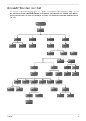
... Cover Keyboard *6 LCD Module *2 Launch Board Lower Case Assembly *2 FDD Module *3 *3 *11 *4 RTC Battery *3 Mini PCI Card Plate Upper Case Assembly Disconnect Wireless LAN Antenna *4 Thermal Module *4 Wireless LAN Antenna Touchpad Cover Wireless LAN Card CPU ODD Module *4 HDD Bracket *1 ODD Support Bracket *1 CPU Heatsink Plate *3 VGA Heatsink Plate Touchpad Button Pad *2 ODD Bracket ODD *4 Main Board Touchpad Touchpad Scroll Key *2 DC Board *2 Speaker Set *4 PCMCIA Slot Touchpad Cable Upper Case Chapter 3 44 For example, if you want to remove the main board...
... Cover Keyboard *6 LCD Module *2 Launch Board Lower Case Assembly *2 FDD Module *3 *3 *11 *4 RTC Battery *3 Mini PCI Card Plate Upper Case Assembly Disconnect Wireless LAN Antenna *4 Thermal Module *4 Wireless LAN Antenna Touchpad Cover Wireless LAN Card CPU ODD Module *4 HDD Bracket *1 ODD Support Bracket *1 CPU Heatsink Plate *3 VGA Heatsink Plate Touchpad Button Pad *2 ODD Bracket ODD *4 Main Board Touchpad Touchpad Scroll Key *2 DC Board *2 Speaker Set *4 PCMCIA Slot Touchpad Cable Upper Case Chapter 3 44 For example, if you want to remove the main board...

Aspire 1500 Service Guide
Page 75
... PCMCIA slot from the lower case. Remove the speaker set cable. See "Removing the Battery" on page 63. 8. See "Removing the ODD Module(1)" on page 46. 2. 9. See "Removing the Middle Cover" on page 64. 10. See "Removing the Main Board" on page 50. 3. See "Removing the HDD Bracket" on page 64. 10. See "Removing the Main Board" on page 63. 9. Removing the Speaker Set 1. Chapter 3 66 See "Removing the Keyboard...
... PCMCIA slot from the lower case. Remove the speaker set cable. See "Removing the Battery" on page 63. 8. See "Removing the ODD Module(1)" on page 46. 2. 9. See "Removing the Middle Cover" on page 64. 10. See "Removing the Main Board" on page 50. 3. See "Removing the HDD Bracket" on page 64. 10. See "Removing the Main Board" on page 63. 9. Removing the Speaker Set 1. Chapter 3 66 See "Removing the Keyboard...

Aspire 1500 Service Guide
Page 105
... devices Initialize all video adapters in system QuietBoot start (optional) Shadow video BIOS ROM Display BIOS copyright notice Display CPU type and speed Initialize EISA board Test keyboard Set key click if enabled Test for unexpected interrupts Initialize POST display service Display prompt "Press F2 to enter SETUP" Disable CPU cache Test RAM between 512 and 640 KB Test extended memory Test extended memory address lines Jump to User Patch1 Configure advanced cache registers Initialize Multi Processor APIC Enable external and CPU caches Setup...
... devices Initialize all video adapters in system QuietBoot start (optional) Shadow video BIOS ROM Display BIOS copyright notice Display CPU type and speed Initialize EISA board Test keyboard Set key click if enabled Test for unexpected interrupts Initialize POST display service Display prompt "Press F2 to enter SETUP" Disable CPU cache Test RAM between 512 and 640 KB Test extended memory Test extended memory address lines Jump to User Patch1 Configure advanced cache registers Initialize Multi Processor APIC Enable external and CPU caches Setup...

Aspire 1500 Service Guide
Page 106
... boot Clear huge ES segment register Fixup Multi Processor table Search for errors POST done- Check for SMART drive (optional) Shadow option ROMs Set up Power Management Initialize security engine (optional) Enable hardware interrupts Determine number of ATA and SCSI drives Set time of ATA drives (optional) Initialize hard-disk controllers Initialize local-bus hard-disk controllers Jump to boot with INT 19 Initialize POST Error Manager (PEM) Initialize error logging Initialize error display function Initialize system error handler PnPnd dual CMOS (optional) Initialize notebook...
... boot Clear huge ES segment register Fixup Multi Processor table Search for errors POST done- Check for SMART drive (optional) Shadow option ROMs Set up Power Management Initialize security engine (optional) Enable hardware interrupts Determine number of ATA and SCSI drives Set time of ATA drives (optional) Initialize hard-disk controllers Initialize local-bus hard-disk controllers Jump to boot with INT 19 Initialize POST Error Manager (PEM) Initialize error logging Initialize error display function Initialize system error handler PnPnd dual CMOS (optional) Initialize notebook...
Aspire 1500 Service Guide
Page 107
... the CPU Initialize the system timer Initialize system I/O Check force recovery boot Checksum BIOS ROM Go to BIOS Set Huge Segment Initialize Multi Processor Initialize OEM special code Initialize PIC and DMA Initialize Memory type Initialize Memory size Shadow Boot Block System memory test Initialize interrupt vectors Initialize Run Time Clock Initialize video Initialize System Management Mode Output one beep before boot Boot to Mini DOS Clear Huge Segment Boot...
... the CPU Initialize the system timer Initialize system I/O Check force recovery boot Checksum BIOS ROM Go to BIOS Set Huge Segment Initialize Multi Processor Initialize OEM special code Initialize PIC and DMA Initialize Memory type Initialize Memory size Shadow Boot Block System memory test Initialize interrupt vectors Initialize Run Time Clock Initialize video Initialize System Management Mode Output one beep before boot Boot to Mini DOS Clear Huge Segment Boot...

Aspire 1500 Service Guide
Page 108
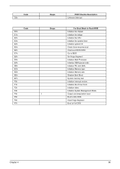
.... Battery pack Power adapter CPU Main board In Windows XP operating system, hold and press the power switch for more than 4 seconds. Main board 99 Chapter 4 Action in characters Abnormal screen Wrong color displayed LCD has extra horizontal or vertical lines displayed. If the system can power off . Index of Symptom-to-FRU Error Message LCD-Related Symptoms Symptom / Error LCD backlight doesn't work ). LCD cable LCD inverter LCD Main board Enter BIOS Utility to execute "Load Setup Default Settings", then reboot...
.... Battery pack Power adapter CPU Main board In Windows XP operating system, hold and press the power switch for more than 4 seconds. Main board 99 Chapter 4 Action in characters Abnormal screen Wrong color displayed LCD has extra horizontal or vertical lines displayed. If the system can power off . Index of Symptom-to-FRU Error Message LCD-Related Symptoms Symptom / Error LCD backlight doesn't work ). LCD cable LCD inverter LCD Main board Enter BIOS Utility to execute "Load Setup Default Settings", then reboot...

Aspire 1500 Service Guide
Page 109
... volume control Audio driver Speaker Main board Speaker Main board Audio driver Volume control in Sequence See "Check the Battery Pack" on , but you hear two long beeps: "B--, B--" and the LCD is damaged. Power-Related Symptoms Symptom / Error Battery can power on page 91. Action in Sequence Power option in Windows XP Hard disk drive Main board Driver of the portable computer. System can 't be inserted or ejected Action in Sequence Enter BIOS Setup Utility to execute "Load Default Settings...
... volume control Audio driver Speaker Main board Speaker Main board Audio driver Volume control in Sequence See "Check the Battery Pack" on , but you hear two long beeps: "B--, B--" and the LCD is damaged. Power-Related Symptoms Symptom / Error Battery can power on page 91. Action in Sequence Power option in Windows XP Hard disk drive Main board Driver of the portable computer. System can 't be inserted or ejected Action in Sequence Enter BIOS Setup Utility to execute "Load Default Settings...
Aspire 1500 Service Guide
Page 110
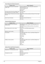
... power off, then charge battery). Reconnect hard disk/CD-ROM drives. Touchpad board Main board 101 Chapter 4 Power Management-Related Symptoms Symptom / Error Action in Sequence The system doesn't resume from standby mode LCD cover switch after opening the lid of the portable computer. Main board Peripheral-Related Symptoms Symptom / Error System configuration does not match the installed devices. Run printer self-test. Device driver Device cable Device Main board Keyboard/Touchpad-Related Symptoms Symptom / Error Keyboard (one or more keys) does not work . Connect AC adapter...
... power off, then charge battery). Reconnect hard disk/CD-ROM drives. Touchpad board Main board 101 Chapter 4 Power Management-Related Symptoms Symptom / Error Action in Sequence The system doesn't resume from standby mode LCD cover switch after opening the lid of the portable computer. Main board Peripheral-Related Symptoms Symptom / Error System configuration does not match the installed devices. Run printer self-test. Device driver Device cable Device Main board Keyboard/Touchpad-Related Symptoms Symptom / Error Keyboard (one or more keys) does not work . Connect AC adapter...
Aspire 1500 Service Guide
Page 112
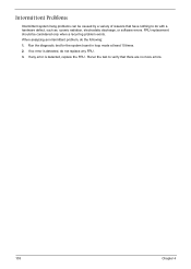
... replace any FRU. 3. Rerun the test to do the following: 1. Run the diagnostic test for the system board in loop mode at least 10 times. 2. Intermittent Problems Intermittent system hang problems can be considered only when a recurring problem exists. When analyzing an intermittent problem, do with a hardware defect, such as: cosmic radiation, electrostatic discharge, or software errors. If no more errors...
... replace any FRU. 3. Rerun the test to do the following: 1. Run the diagnostic test for the system board in loop mode at least 10 times. 2. Intermittent Problems Intermittent system hang problems can be considered only when a recurring problem exists. When analyzing an intermittent problem, do with a hardware defect, such as: cosmic radiation, electrostatic discharge, or software errors. If no more errors...
Aspire 1500 Service Guide
Page 135
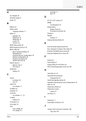
... package 18 type 18 D DC-AC LCD Inverter 23 DIMM Combinations 19 Disassembly Battery Pack 45 Procedure Flowchart 44 Display 2 display hotkeys 15 Display Standby Mode 25 E Environmental Requirements 25 Error Symptom-to-Spare Part Index 92 External CD-ROM Drive Check 89 External Diskette Drive Check 89 F Features 1 Flash Utility 41 Floppy Disk Drive Interface 20 FRU (Field Replaceable Unit) List 108 H Hard disk 18, 20 Hard Disk Drive Module Disassembly 49 Hard Disk Standby Mode 25 Hardware Specifications and Configurations 18 HDD 18, 20...
... package 18 type 18 D DC-AC LCD Inverter 23 DIMM Combinations 19 Disassembly Battery Pack 45 Procedure Flowchart 44 Display 2 display hotkeys 15 Display Standby Mode 25 E Environmental Requirements 25 Error Symptom-to-Spare Part Index 92 External CD-ROM Drive Check 89 External Diskette Drive Check 89 F Features 1 Flash Utility 41 Floppy Disk Drive Interface 20 FRU (Field Replaceable Unit) List 108 H Hard disk 18, 20 Hard Disk Drive Module Disassembly 49 Hard Disk Standby Mode 25 Hardware Specifications and Configurations 18 HDD 18, 20...


