
Aspire 1400 Notebook Service Guide
Page 9
Video performance is boosted with on-die level 2 cache 256 MB memory expandable to 1G High-capacity, Enhanced-IDE hard disk Lithium-Ion battery pack Power management system Display The large graphics display offers excellent viewing, display quality and desktop-performance graphics. ! Chapter 1 System Specifications Features This computer was ...
Video performance is boosted with on-die level 2 cache 256 MB memory expandable to 1G High-capacity, Enhanced-IDE hard disk Lithium-Ion battery pack Power management system Display The large graphics display offers excellent viewing, display quality and desktop-performance graphics. ! Chapter 1 System Specifications Features This computer was ...
Aspire 1400 Notebook Service Guide
Page 20
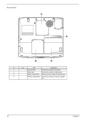
Bottom Panel # Icon Item Description 1 Hard disk bay Houses the computer's hard disk. 2 Battery bay Houses the computer's battery pack. 3 Battery release latch Slide and hold to unlatch the battery pack. 4 Memory compartment Houses the computer's memory upgrade slot. 14 Chapter 1
Bottom Panel # Icon Item Description 1 Hard disk bay Houses the computer's hard disk. 2 Battery bay Houses the computer's battery pack. 3 Battery release latch Slide and hold to unlatch the battery pack. 4 Memory compartment Houses the computer's memory upgrade slot. 14 Chapter 1
Aspire 1400 Notebook Service Guide
Page 22
Wireless networking Optical drive activity Wireless networking feature is being accessed. C. Use the wireless networking switch to enable or disable this switch. Hard disk activity Hard disk is enabled. Audio DJ mode indicators Media Player Audio DJ to Microsoft Media Player is being accessed. See "Right view" on page 6 for the location for the location of this feature. Icon Function Description Battery charge Battery is set to CD playback. 16 Chapter 1 Optical drive (CD or DVD) is set . CD Audio DJ is being charged.
Wireless networking Optical drive activity Wireless networking feature is being accessed. C. Use the wireless networking switch to enable or disable this switch. Hard disk activity Hard disk is enabled. Audio DJ mode indicators Media Player Audio DJ to Microsoft Media Player is being accessed. See "Right view" on page 6 for the location for the location of this feature. Icon Function Description Battery charge Battery is set to CD playback. 16 Chapter 1 Optical drive (CD or DVD) is set . CD Audio DJ is being charged.
Aspire 1400 Notebook Service Guide
Page 36
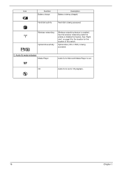
... burst mode is that come form system to control lamp brightness. Wide range 9V to21V input voltage. 2. Battery Item Vendor & model name Battery Type Pack capacity Cell voltage Number of battery cell Package configuration Package voltage Specification Sony Li-ion 57Wh 3.7V/cell 12 4 cells in series, 3 ...by PWM duty mode. 30 Chapter 1 This inverter brightness is named PWM, which limits current to light up the CCFL of LCD for Aspire 1400 notebook. The effective brightness is named DAC_BRIG, which adjusts lamp brightness. Birghtness adjustment by PWM burst mode. One signal is a function...
... burst mode is that come form system to control lamp brightness. Wide range 9V to21V input voltage. 2. Battery Item Vendor & model name Battery Type Pack capacity Cell voltage Number of battery cell Package configuration Package voltage Specification Sony Li-ion 57Wh 3.7V/cell 12 4 cells in series, 3 ...by PWM duty mode. 30 Chapter 1 This inverter brightness is named PWM, which limits current to light up the CCFL of LCD for Aspire 1400 notebook. The effective brightness is named DAC_BRIG, which adjusts lamp brightness. Birghtness adjustment by PWM burst mode. One signal is a function...

Aspire 1400 Notebook Service Guide
Page 51
The table below describes the parameters in boldface are the default and suggested parameter settings. Settings in this screen. Options Enabled or Disabled Enabled or Disabled Disabled or Enabled Chapter 2 45 Determines whether or not the system will alarm when the battery power is closed. Parameter Low Battery Alarm Panel Close Alarm System Beep Description Determines whether or not the system will alarm when the display cover is low. Others The Others screen contains various parameter settings. Determines whether or not the system will emit a beep on boot up.
The table below describes the parameters in boldface are the default and suggested parameter settings. Settings in this screen. Options Enabled or Disabled Enabled or Disabled Disabled or Enabled Chapter 2 45 Determines whether or not the system will alarm when the battery power is closed. Parameter Low Battery Alarm Panel Close Alarm System Beep Description Determines whether or not the system will alarm when the display cover is low. Others The Others screen contains various parameter settings. Determines whether or not the system will emit a beep on boot up.
Aspire 1400 Notebook Service Guide
Page 54
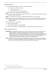
... of system programs ! NOTE: If you may not boot the system because the BIOS is provided by Acer Headquarters. If the battery pack does not contain enough power to employ in the Aspire 1400 service CD kit. BIOS Phlash Utility The BIOS flash memory update is required for the following items... for Aspire 1400 is not exactly the same as a basic diagnostic tool. Restore a BIOS when it as PQA (...
... of system programs ! NOTE: If you may not boot the system because the BIOS is provided by Acer Headquarters. If the battery pack does not contain enough power to employ in the Aspire 1400 service CD kit. BIOS Phlash Utility The BIOS flash memory update is required for the following items... for Aspire 1400 is not exactly the same as a basic diagnostic tool. Restore a BIOS when it as PQA (...

Aspire 1400 Notebook Service Guide
Page 60
13. Battery Charge Test Insert AC adapter to the sytem, then run "591NEW2.exe" for testing. 54 Chapter 2
13. Battery Charge Test Insert AC adapter to the sytem, then run "591NEW2.exe" for testing. 54 Chapter 2
Aspire 1400 Notebook Service Guide
Page 62
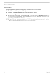
...too long may need to fasten the FFC/FPC/connectors/cable, you may damage the main board as you do the following: 1. NOTE: Aspire 1400 uses mylar or tape to tear the tape or mylar before you use the right screws. Please make sure that are M2.5x4. Otherwise..., other screws that you secure the power board to the system and all power and signal cables from the system. 3. Remove the battery pack. 4. Unplug the AC adapter and all peripherals. 2. General Information Before You Begin Before proceeding with the disassembly procedure, make sure you disconnect ...
...too long may need to fasten the FFC/FPC/connectors/cable, you may damage the main board as you do the following: 1. NOTE: Aspire 1400 uses mylar or tape to tear the tape or mylar before you use the right screws. Please make sure that are M2.5x4. Otherwise..., other screws that you secure the power board to the system and all power and signal cables from the system. 3. Remove the battery pack. 4. Unplug the AC adapter and all peripherals. 2. General Information Before You Begin Before proceeding with the disassembly procedure, make sure you disconnect ...
Aspire 1400 Notebook Service Guide
Page 63
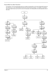
Start Battery Ex2 HDD Module Disconnect FDD FPC Ex1 FDD Module Jx4 HDD Drive Jx2 HDD EMI Plate FDD FPC HDD Connector Panasoni: Ex2 MIT: GX2 FDD ...
Start Battery Ex2 HDD Module Disconnect FDD FPC Ex1 FDD Module Jx4 HDD Drive Jx2 HDD EMI Plate FDD FPC HDD Connector Panasoni: Ex2 MIT: GX2 FDD ...
Aspire 1400 Notebook Service Guide
Page 65
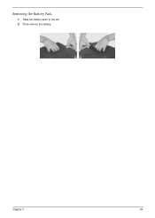
Chapter 3 59 Slide the battery latch to the left. 2. Then remove the battery. Removing the Battery Pack 1.
Chapter 3 59 Slide the battery latch to the left. 2. Then remove the battery. Removing the Battery Pack 1.
Aspire 1400 Notebook Service Guide
Page 77
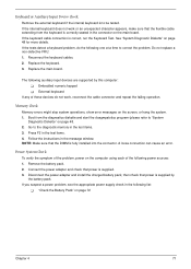
...from the diagnostics diskette and start the doagmpstotics program (please refer to correct the problem. Disconnect the power adapter and install the charged battery pack; If you suspect a power problem, see the appropriate power supply check in the message window. Power System Check To verify ... the keyboard. 3. Replace the main board. External keyboard If any of the following auxiliary input devices are supported by the battery pack. "Check the Battery Pack" on page 48. 2. Boot from the keyboard is correctly seated in the connector on the computer using each of these...
...from the diagnostics diskette and start the doagmpstotics program (please refer to correct the problem. Disconnect the power adapter and install the charged battery pack; If you suspect a power problem, see the appropriate power supply check in the message window. Power System Check To verify ... the keyboard. 3. Replace the main board. External keyboard If any of the following auxiliary input devices are supported by the battery pack. "Check the Battery Pack" on page 48. 2. Boot from the keyboard is correctly seated in the connector on the computer using each of these...
Aspire 1400 Notebook Service Guide
Page 78
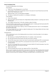
... PS2 Mode Driver. Replace switch board. 7. If the voltage is working. 3. If the charge indicator still does not light up , remove the battery pack and let it return to room temperature. Do not replace a non-defective FRU: 1. Run utility with the PS/2 mouse function and check if...to switch board FPC is on recharging or discharging. This helps you use a discharged battery pack or a battery pack that if the parameters shown in control Panel 2. Remove the battery pack and measure the voltage between battery terminals 1(+) and 6(ground). If yes, then replace touch pad PCB. This symptom ...
... PS2 Mode Driver. Replace switch board. 7. If the voltage is working. 3. If the charge indicator still does not light up , remove the battery pack and let it return to room temperature. Do not replace a non-defective FRU: 1. Run utility with the PS/2 mouse function and check if...to switch board FPC is on recharging or discharging. This helps you use a discharged battery pack or a battery pack that if the parameters shown in control Panel 2. Remove the battery pack and measure the voltage between battery terminals 1(+) and 6(ground). If yes, then replace touch pad PCB. This symptom ...
Aspire 1400 Notebook Service Guide
Page 80
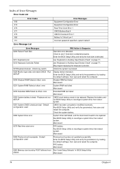
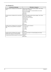
... Input Device Check" on page 71. Enter the BIOS Setup Utility and verify the parameters (try loading the default settings); RTC battery Main board Run "Load Setup Defaults" in Sequence Hard disk error detected. Replace and run BIOS Setup Utility to reconfigure system time...071 072 080 110 Error Message List Error Messages Equipment Configuration Error Equipment Configuration Error Real Time Clock Error 1 CMOS Battery Bad 4 CMOS Checksum Error 1 Battery Is Critical Low 1 Incorrect password specified, system halted 1 Error Messages 0200 Failure Fixed Disk 0211 Keyboard error 0212 ...
... Input Device Check" on page 71. Enter the BIOS Setup Utility and verify the parameters (try loading the default settings); RTC battery Main board Run "Load Setup Defaults" in Sequence Hard disk error detected. Replace and run BIOS Setup Utility to reconfigure system time...071 072 080 110 Error Message List Error Messages Equipment Configuration Error Equipment Configuration Error Real Time Clock Error 1 CMOS Battery Bad 4 CMOS Checksum Error 1 Battery Is Critical Low 1 Incorrect password specified, system halted 1 Error Messages 0200 Failure Fixed Disk 0211 Keyboard error 0212 ...
Aspire 1400 Notebook Service Guide
Page 81
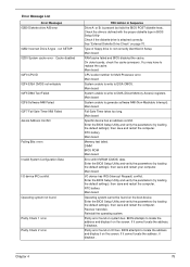
... RAM cache failed and BIOS disabled the cache. Enter the BIOS Setup Utility and verify the parameters (try loading the default settings); RTC battery Main board Memery test failed. DIMM BIOS ROM Main board Error with the proper diskette type in Sequence Drive A: or B: is attached ...correctly. Parity error found on the screen. Chapter 4 75 Main board CPU socket number for Multi-Processor error. RTC battery Main board Operating system cannot be found Parity Check 1 nnnn Parity Check 2 nnnn FRU/Action in BIOS Setup Utility Check if the diskette drive...
... RAM cache failed and BIOS disabled the cache. Enter the BIOS Setup Utility and verify the parameters (try loading the default settings); RTC battery Main board Memery test failed. DIMM BIOS ROM Main board Error with the proper diskette type in Sequence Drive A: or B: is attached ...correctly. Parity error found on the screen. Chapter 4 75 Main board CPU socket number for Multi-Processor error. RTC battery Main board Operating system cannot be found Parity Check 1 nnnn Parity Check 2 nnnn FRU/Action in BIOS Setup Utility Check if the diskette drive...
Aspire 1400 Notebook Service Guide
Page 82
... System Check" on page 71. But you can see POST on indicator turns off and LCD is blank. Power source (battery pack and power adapter). Reconnect the DIMM. Power source (battery pack and power adapter). Ensure every connector is connected tightly and correctly. Speaker Main board 76 Chapter 4 Ensure every connector is...
... System Check" on page 71. But you can see POST on indicator turns off and LCD is blank. Power source (battery pack and power adapter). Reconnect the DIMM. Power source (battery pack and power adapter). Ensure every connector is connected tightly and correctly. Speaker Main board 76 Chapter 4 Ensure every connector is...
Aspire 1400 Notebook Service Guide
Page 83
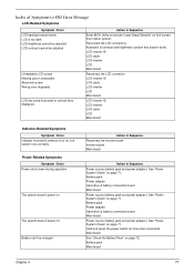
...runs correctly Power-Related Symptoms Symptom / Error Power shuts down during operation The system doesn't power-on page 71. Battery can't be adjusted Unreadable LCD screen Missing pels in characters Abnormal screen Wrong color displayed LCD has extra horizontal or vertical lines ... LCD backlight doesn't work ). See "Power System Check" on Exit screen, then reboot system. Battery pack Main board Chapter 4 77 Reconnect the LCD connectors. Action in Sequence Power source (battery pack and power adapter). See "Power System Check" on page 72. Main board See "Check...
...runs correctly Power-Related Symptoms Symptom / Error Power shuts down during operation The system doesn't power-on page 71. Battery can't be adjusted Unreadable LCD screen Missing pels in characters Abnormal screen Wrong color displayed LCD has extra horizontal or vertical lines ... LCD backlight doesn't work ). See "Power System Check" on Exit screen, then reboot system. Battery pack Main board Chapter 4 77 Reconnect the LCD connectors. Action in Sequence Power source (battery pack and power adapter). See "Power System Check" on page 72. Main board See "Check...
Aspire 1400 Notebook Service Guide
Page 84
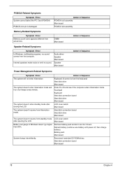
...Related Symptoms Symptom / Error In Windows, multimedia programs, no sound. Hard disk connection board Main board 78 Chapter 4 Main board Battery fuel gauge in Sequence The system will not enter hibernation Keyboard (if control is damaged. PCMCIA-Related Symptoms Symptom / Error System ...is from the keyboard) Hard disk drive Main board The system doesn't enter hibernation mode and four short beeps every minute. Battery pack Main board System hangs intermittently. Hard disk connection board Hard disk drive Main board The system doesn't resume from actual ...
...Related Symptoms Symptom / Error In Windows, multimedia programs, no sound. Hard disk connection board Main board 78 Chapter 4 Main board Battery fuel gauge in Sequence The system will not enter hibernation Keyboard (if control is damaged. PCMCIA-Related Symptoms Symptom / Error System ...is from the keyboard) Hard disk drive Main board The system doesn't enter hibernation mode and four short beeps every minute. Battery pack Main board System hangs intermittently. Hard disk connection board Hard disk drive Main board The system doesn't resume from actual ...
Aspire 1400 Notebook Service Guide
Page 87
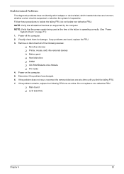
... at the time of the following FRU one at a time. If the problem remains, replace the following devices: ! LCD assembly Chapter 4 81 Battery pack ! Do not replace a non-defective FRU: ! Visually check them for damage. Hard disk drive ! Power-on page 71): 1. Power-...off the computer. 2. Determine if the problem has changed. 6. NOTE: Verify that all of the failure is inoperative. Non-Acer devices ! Main board ! Printer, mouse, and other external devices ! CD-ROM/Diskette drive Module ! NOTE: Verify that the power supply being ...
... at the time of the following FRU one at a time. If the problem remains, replace the following devices: ! LCD assembly Chapter 4 81 Battery pack ! Do not replace a non-defective FRU: ! Visually check them for damage. Hard disk drive ! Power-on page 71): 1. Power-...off the computer. 2. Determine if the problem has changed. 6. NOTE: Verify that all of the failure is inoperative. Non-Acer devices ! Main board ! Printer, mouse, and other external devices ! CD-ROM/Diskette drive Module ! NOTE: Verify that the power supply being ...

Aspire 1400 Notebook Service Guide
Page 88
Make sure this AFlash BIOS diskette for this diskette. Index of AFlash BIOS Error Message Error Message Hardware Error VPD Checksum Error BIOS Update Program Error System Error Without AC adapter Battery Low Action in Sequence See "System Diagnostic Diskette" on page 48 Reboot the system and then restest with this model. Turn off the power and restart the system. make sure to connect AC adapter make sure to install a highly charged battery, and reboot system. 82 Chapter 4
Make sure this AFlash BIOS diskette for this diskette. Index of AFlash BIOS Error Message Error Message Hardware Error VPD Checksum Error BIOS Update Program Error System Error Without AC adapter Battery Low Action in Sequence See "System Diagnostic Diskette" on page 48 Reboot the system and then restest with this model. Turn off the power and restart the system. make sure to connect AC adapter make sure to install a highly charged battery, and reboot system. 82 Chapter 4
Aspire 1400 Notebook Service Guide
Page 106
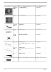
Picture No. 008-Logic Upper Partname And Description TOUCHPAD BRACKET Part Number 33.A02V5.002 311-The System HEATSINK BRACKET 33.A02V5.003 002-Logic Upper LED BRACKET 310-The System D-SUB BRACKET 312-The System CPU SUPPORT BRACKET 33.A02V5.004 33.A02V5.005 33.A02V5.006 006-Logic Upper HINGE SADDLE-R Note: The image includes right and left hinge saddles. 34.A02V5.001 007-Logic Upper HINGE SADDLE-L Note: The image includes right and left hinge saddles. 34.A02V5.002 NS BATTERY LATCH 42.A02V5.004 NS BATTERY LATCH KNOB V42.A02V5.005 100 Chapter 6
Picture No. 008-Logic Upper Partname And Description TOUCHPAD BRACKET Part Number 33.A02V5.002 311-The System HEATSINK BRACKET 33.A02V5.003 002-Logic Upper LED BRACKET 310-The System D-SUB BRACKET 312-The System CPU SUPPORT BRACKET 33.A02V5.004 33.A02V5.005 33.A02V5.006 006-Logic Upper HINGE SADDLE-R Note: The image includes right and left hinge saddles. 34.A02V5.001 007-Logic Upper HINGE SADDLE-L Note: The image includes right and left hinge saddles. 34.A02V5.002 NS BATTERY LATCH 42.A02V5.004 NS BATTERY LATCH KNOB V42.A02V5.005 100 Chapter 6


