Aspire 1400 Notebook Service Guide
Page 7
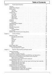
... Diagram 5 Board Layout 6 Top View 6 Bottom View 7 Outlook View 9 Front View 9 Left Panel 11 Right Panel 12 Rear Panel 13 Bottom Panel 14 Indicators 15 Keyboard 17 Lock Keys 17 Embedded Numeric Keypad 18 Windows Keys 19 Hot Keys 20 Keyboard Ergonomics 21 Touchpad 22 Touchpad Basics 22 Launch Keys 24 Hardware Specifications and Configurations 25 Chapter 2 System Utilities 37 BIOS Setup Utility 37 Navigating the BIOS Utility 37 Main 38 Advanced 40 Security 42 Others 45 Boot...
... Diagram 5 Board Layout 6 Top View 6 Bottom View 7 Outlook View 9 Front View 9 Left Panel 11 Right Panel 12 Rear Panel 13 Bottom Panel 14 Indicators 15 Keyboard 17 Lock Keys 17 Embedded Numeric Keypad 18 Windows Keys 19 Hot Keys 20 Keyboard Ergonomics 21 Touchpad 22 Touchpad Basics 22 Launch Keys 24 Hardware Specifications and Configurations 25 Chapter 2 System Utilities 37 BIOS Setup Utility 37 Navigating the BIOS Utility 37 Main 38 Advanced 40 Security 42 Others 45 Boot...
Aspire 1400 Notebook Service Guide
Page 19
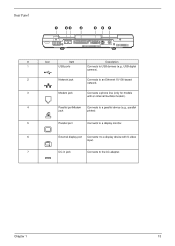
Chapter 1 13 Rear Panel # Icon Item Description 1 USB ports Connects to USB devices (e.g., USB digital camera). 2 Network jack Connects to an Ethernet 10/100-based network. 3 Modem jack Connects a phone line (only for models with an internal fax/data modem). 4 Parallel portModem Connects to a parallel device (e.g., parallel jack printer). 5 Parallel port Connects to a display monitor. 6 External display port Connects t to a display device with S-video input. 7 DC-in jack Connects to the AC adapter.
Chapter 1 13 Rear Panel # Icon Item Description 1 USB ports Connects to USB devices (e.g., USB digital camera). 2 Network jack Connects to an Ethernet 10/100-based network. 3 Modem jack Connects a phone line (only for models with an internal fax/data modem). 4 Parallel portModem Connects to a parallel device (e.g., parallel jack printer). 5 Parallel port Connects to a display monitor. 6 External display port Connects t to a display device with S-video input. 7 DC-in jack Connects to the AC adapter.
Aspire 1400 Notebook Service Guide
Page 23
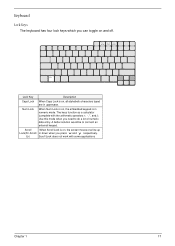
... and off. Use this mode when you need to connect an external keypad. Lock Key Description Caps Lock When Caps Lock is in uppercase. Keyboard Lock Keys The keyboard has four lock keys which you can toggle on , all alphabetic characters typed are in numeric mode. A better solution would be to do a lot of numeric data entry. Lk) Scroll Lock does not work with the arithmetic operators +, -, *, and /). The keys function as a calculator...
... and off. Use this mode when you need to connect an external keypad. Lock Key Description Caps Lock When Caps Lock is in uppercase. Keyboard Lock Keys The keyboard has four lock keys which you can toggle on , all alphabetic characters typed are in numeric mode. A better solution would be to do a lot of numeric data entry. Lk) Scroll Lock does not work with the arithmetic operators +, -, *, and /). The keys function as a calculator...
Aspire 1400 Notebook Service Guide
Page 40
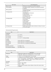
... states and data onto disk prior to -read lock indicators, Status indicators, Power LED, Audio DJ mode indicators Chapter 1 All devices in the system are turned off back-light PCMCIA Standby Hard Disk Spin Down motor CD-ROM Spin Down Super I/O Power down CPU set power down VGA Suspend PCMCIA Suspend Audio Suspend Hard Disk Power Down CD-ROM Power Down Super I /O Ports Drive Bays Material Indicators 34 Specification 329mm (W) x 279mm (D) x 42.3/52.8mm(H) for 14.1 LCD model 335mm(W) x 295mm (D) x 42...
... states and data onto disk prior to -read lock indicators, Status indicators, Power LED, Audio DJ mode indicators Chapter 1 All devices in the system are turned off back-light PCMCIA Standby Hard Disk Spin Down motor CD-ROM Spin Down Super I/O Power down CPU set power down VGA Suspend PCMCIA Suspend Audio Suspend Hard Disk Power Down CD-ROM Power Down Super I /O Ports Drive Bays Material Indicators 34 Specification 329mm (W) x 279mm (D) x 42.3/52.8mm(H) for 14.1 LCD model 335mm(W) x 295mm (D) x 42...
Aspire 1400 Notebook Service Guide
Page 49
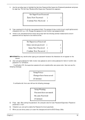
... save the changes and exit the BIOS Setup Utility. Type a password in the Confirm new password field. 3. Set Supervisor Password Enter current password [ ] Enter New Password [ ] Confirm New Password [ ] IMPORTANT:Be very careful when typing your password because the characters do not appear on boot parameter. 7. Retype the password in the Enter new password field. When you can opt to eight alphanumeric characters (A-Z, a-z, 0-9). Use the w andy keys to "Set". 6. User can type password in field of enter new password, and re-enter password in field...
... save the changes and exit the BIOS Setup Utility. Type a password in the Confirm new password field. 3. Set Supervisor Password Enter current password [ ] Enter New Password [ ] Confirm New Password [ ] IMPORTANT:Be very careful when typing your password because the characters do not appear on boot parameter. 7. Retype the password in the Enter new password field. When you can opt to eight alphanumeric characters (A-Z, a-z, 0-9). Use the w andy keys to "Set". 6. User can type password in field of enter new password, and re-enter password in field...
Aspire 1400 Notebook Service Guide
Page 50
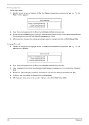
... the BIOS Setup Utility. If desired, you can enable the Password on boot parameter. 6. Changing a Password 1. Type the current password in the Enter New Password and Confirm New Password fields. After setting the password, the computer sets the User Password parameter to highlight the Set User Password parameter and press the e key. Press e twice without typing anything in the Enter Current Password field and press e. 3. The computer then sets the User Password parameter to highlight the Set User Password parameter and press the e key. Removing a Password...
... the BIOS Setup Utility. If desired, you can enable the Password on boot parameter. 6. Changing a Password 1. Type the current password in the Enter New Password and Confirm New Password fields. After setting the password, the computer sets the User Password parameter to highlight the Set User Password parameter and press the e key. Press e twice without typing anything in the Enter Current Password field and press e. 3. The computer then sets the User Password parameter to highlight the Set User Password parameter and press the e key. Removing a Password...
Aspire 1400 Notebook Service Guide
Page 54
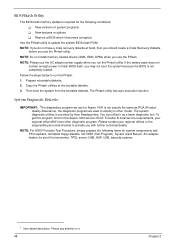
.... NOTE: Do not install memory-related drivers (XMS, EMS, DPMI) when you may not boot the system because the BIOS is provided by Acer Headquarters. NOTE: Please use for system components test: PIO loopback, formatted floppy diskette, CD-DISK (Test Program), Sycard (Card Bus)x2, AC-adapter, feather (to see if the fan works), TPDL server, USB_HUP, USB_barcode scanner. 1 New added description. Prepare a bootable...
.... NOTE: Do not install memory-related drivers (XMS, EMS, DPMI) when you may not boot the system because the BIOS is provided by Acer Headquarters. NOTE: Please use for system components test: PIO loopback, formatted floppy diskette, CD-DISK (Test Program), Sycard (Card Bus)x2, AC-adapter, feather (to see if the fan works), TPDL server, USB_HUP, USB_barcode scanner. 1 New added description. Prepare a bootable...
Aspire 1400 Notebook Service Guide
Page 63
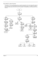
... on the components that order. Start Battery Ex2 HDD Module Disconnect FDD FPC Ex1 FDD Module Jx4 HDD Drive Jx2 HDD EMI Plate FDD FPC HDD Connector Panasoni: Ex2 MIT: GX2 FDD Panel Ex4 RAM Door Ex2 Antenna Covers Wireless LAN Card Ex1 Optical Drive Optical Panel Ax2 Optical Bracket Ex2 LED power board LS- 1257 Stripe Cover Disconenct Keyboard FFC Ex2 Keyboard Ex1 EMI Bar Disconnect coaxial cable Fx4 LCD Module Ex2 LCD Bezel Ex6 Dx2 Ex1...
... on the components that order. Start Battery Ex2 HDD Module Disconnect FDD FPC Ex1 FDD Module Jx4 HDD Drive Jx2 HDD EMI Plate FDD FPC HDD Connector Panasoni: Ex2 MIT: GX2 FDD Panel Ex4 RAM Door Ex2 Antenna Covers Wireless LAN Card Ex1 Optical Drive Optical Panel Ax2 Optical Bracket Ex2 LED power board LS- 1257 Stripe Cover Disconenct Keyboard FFC Ex2 Keyboard Ex1 EMI Bar Disconnect coaxial cable Fx4 LCD Module Ex2 LCD Bezel Ex6 Dx2 Ex1...
Aspire 1400 Notebook Service Guide
Page 67
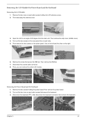
... keyboard FFC. After disconnect the keyboard connector then remove the keyboard. Disconnect the coaxial cable connector. 8. Turn out the two (one on each side. 5. Then remove the strip cover (middle cover). 4. Then remove the two screws on the right. 6. Removing the Power Board and the Keyboard 1. Open the LCD to an angle of 95 degree from the main unit. Chapter 3 61 Removing the LCD Module/the Power Board and the Keyboard Removing the LCD Module 1. Remove...
... keyboard FFC. After disconnect the keyboard connector then remove the keyboard. Disconnect the coaxial cable connector. 8. Turn out the two (one on each side. 5. Then remove the strip cover (middle cover). 4. Then remove the two screws on the right. 6. Removing the Power Board and the Keyboard 1. Open the LCD to an angle of 95 degree from the main unit. Chapter 3 61 Removing the LCD Module/the Power Board and the Keyboard Removing the LCD Module 1. Remove...
Aspire 1400 Notebook Service Guide
Page 80
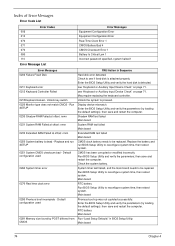
... Sequence Hard disk error detected. Default configuration used 0281 Memory size found by POST differed from CMOS FRU/Action in BIOS Setup Utility. see "Keyboard or Auxiliary Input Device Check" on page 71. Shadow RAM test failed Main board System RAM test failed Main board Extended RAM test failed Main board CMOS clock battery needs to reconfigure system time, then reboot system. Main board Previous boot-up was not copleted successfully. Main board 74 Chapter 4 Unlock key switch 0220 Monitor type...
... Sequence Hard disk error detected. Default configuration used 0281 Memory size found by POST differed from CMOS FRU/Action in BIOS Setup Utility. see "Keyboard or Auxiliary Input Device Check" on page 71. Shadow RAM test failed Main board System RAM test failed Main board Extended RAM test failed Main board CMOS clock battery needs to reconfigure system time, then reboot system. Main board Previous boot-up was not copleted successfully. Main board 74 Chapter 4 Unlock key switch 0220 Monitor type...
Aspire 1400 Notebook Service Guide
Page 83
... pack and power adapter). Battery pack Power adapter Hard drive & battery connection board Main board Power source (battery pack and power adapter). Action in Sequence Enter BIOS Utility to -FRU Error Message LCD-Related Symptoms Symptom / Error LCD backlight doesn't work ). Reconnect the LCD connectors. Keyboard (if contrast and brightness function key doesn't work LCD is too dark LCD brightness cannot be adjusted LCD contrast cannot be charged Action in Sequence Reconnect the inverter board Inverter board Main board Action in characters Abnormal screen Wrong color displayed LCD has...
... pack and power adapter). Battery pack Power adapter Hard drive & battery connection board Main board Power source (battery pack and power adapter). Action in Sequence Enter BIOS Utility to -FRU Error Message LCD-Related Symptoms Symptom / Error LCD backlight doesn't work ). Reconnect the LCD connectors. Keyboard (if contrast and brightness function key doesn't work LCD is too dark LCD brightness cannot be adjusted LCD contrast cannot be charged Action in Sequence Reconnect the inverter board Inverter board Main board Action in characters Abnormal screen Wrong color displayed LCD has...
Aspire 1400 Notebook Service Guide
Page 85
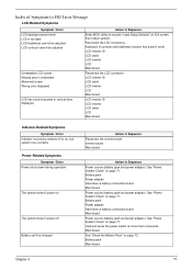
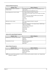
...USB does not work . Onboard Devices Configuration Run printer self-test. Power off. Touchpad does not work correctly Print problems. Action in Sequence Internal modem does not work . Chapter 4 79 Reconnect hard disk/CD-ROM/diskette drives. Then check if RAM CPU BIOS are well-connected. Printer driver Printer cable Printer Main board Keyboard/Touchpad-Related Symptoms Symptom / Error Keyboard (one or more keys) does not work correctly. Touchpad board Main board Modem-Related Symptoms Symptom / Error Action in Sequence Enter BIOS Setup Utility to Enabled...
...USB does not work . Onboard Devices Configuration Run printer self-test. Power off. Touchpad does not work correctly Print problems. Action in Sequence Internal modem does not work . Chapter 4 79 Reconnect hard disk/CD-ROM/diskette drives. Then check if RAM CPU BIOS are well-connected. Printer driver Printer cable Printer Main board Keyboard/Touchpad-Related Symptoms Symptom / Error Keyboard (one or more keys) does not work correctly. Touchpad board Main board Modem-Related Symptoms Symptom / Error Action in Sequence Enter BIOS Setup Utility to Enabled...
Aspire 1400 Notebook Service Guide
Page 117
... 26 external 60 removing 60 Disassembly Battery Pack 58 CD-ROM/DVD-ROM Module 62 Floppy Disk Drive 66 Machine 55 Procedure Flowchart 57 Display 5 DVD-ROM Interface 27 E Error Symptom-to-Spare Part Index 73 External CD-ROM Drive Check 70 External Diskette Drive Check 70 F Features 3 features 105 Flash Utility 48 Floppy Disk removing the 66 Floppy Disk Drive Interface 26 FRU (Field Replaceable Unit) List 87 H Hard disk 26, 29 Hardware Specifications and Configurations 24 HDD 26, 29 Hot Keys 17 I Indicators 15 Intermittent Problems...
... 26 external 60 removing 60 Disassembly Battery Pack 58 CD-ROM/DVD-ROM Module 62 Floppy Disk Drive 66 Machine 55 Procedure Flowchart 57 Display 5 DVD-ROM Interface 27 E Error Symptom-to-Spare Part Index 73 External CD-ROM Drive Check 70 External Diskette Drive Check 70 F Features 3 features 105 Flash Utility 48 Floppy Disk removing the 66 Floppy Disk Drive Interface 26 FRU (Field Replaceable Unit) List 87 H Hard disk 26, 29 Hardware Specifications and Configurations 24 HDD 26, 29 Hot Keys 17 I Indicators 15 Intermittent Problems...
Aspire 1400 User Guide
Page 17
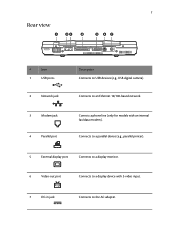
7 Rear view # Item 1 USB ports 2 Network jack 3 Modem jack 4 Parallel port Description Connects to an Ethernet 10/100-based network. Connects to USB devices (e.g., USB digital camera). Conncts a phone line (only for models with S-video input. 7 DC-in jack Connects to the AC adapter. Connects to a parallel device (e.g., parallel printer). 5 External display port Connects to a display monitor. 6 Video-out port Connects to a display device with an internal fax/data modem).
7 Rear view # Item 1 USB ports 2 Network jack 3 Modem jack 4 Parallel port Description Connects to an Ethernet 10/100-based network. Connects to USB devices (e.g., USB digital camera). Conncts a phone line (only for models with S-video input. 7 DC-in jack Connects to the AC adapter. Connects to a parallel device (e.g., parallel printer). 5 External display port Connects to a display monitor. 6 Video-out port Connects to a display device with an internal fax/data modem).
Aspire 1400 User Guide
Page 52
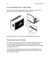
... projector with s-video input You can choose to connect the display device to the computer through the external display port or video-out port, depending on the other external display. So whatever is displayed in your TV or projector for your computer will likewise be displayed on what your display device supports. Press Fn-F5 to toggle the display output location. Read the manual for additional operating instructions. Using simultaneous display Your computer...
... projector with s-video input You can choose to connect the display device to the computer through the external display port or video-out port, depending on the other external display. So whatever is displayed in your TV or projector for your computer will likewise be displayed on what your display device supports. Press Fn-F5 to toggle the display output location. Read the manual for additional operating instructions. Using simultaneous display Your computer...
Aspire 1400 User Guide
Page 59
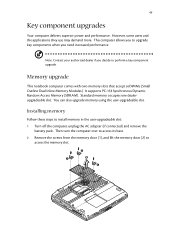
... upgrade key components when you to perform a key component upgrade. Memory upgrade This notebook computer comes with two memory slots that accept soDIMMs (Small Outline Dual Inline Memory Modules). Standard memory occupies one dealerupgradeable slot. However, some users and the applications they use may demand more. It supports PC-133 Synchronous Dynamic Random Access Memory (SDRAM). Installing memory Follow these steps to access the memory slot. Then turn the computer over to access its base. 2 Remove...
... upgrade key components when you to perform a key component upgrade. Memory upgrade This notebook computer comes with two memory slots that accept soDIMMs (Small Outline Dual Inline Memory Modules). Standard memory occupies one dealerupgradeable slot. However, some users and the applications they use may demand more. It supports PC-133 Synchronous Dynamic Random Access Memory (SDRAM). Installing memory Follow these steps to access the memory slot. Then turn the computer over to access its base. 2 Remove...
Aspire 1400 User Guide
Page 77
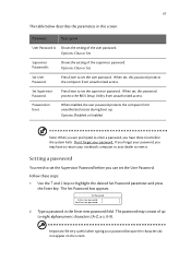
...of the supervisor password. When set the user password. Setting a password You need to reset it. The Set Password box appears: Set Password Enter new password: [ ] Confirm new password: [ ] 2 Type a password in this screen. When set, this password protects the BIOS Setup Utility from unauthorized access during boot up to set , this password protects the computer from unauthorized access. Options: Clear or Set Set User Password Press Enter to eight alphanumeric characters (A-Z, a-z, 0-9). Password on the screen. Options: Disabled or Enabled Note: When you...
...of the supervisor password. When set the user password. Setting a password You need to reset it. The Set Password box appears: Set Password Enter new password: [ ] Confirm new password: [ ] 2 Type a password in this screen. When set, this password protects the BIOS Setup Utility from unauthorized access during boot up to set , this password protects the computer from unauthorized access. Options: Clear or Set Set User Password Press Enter to eight alphanumeric characters (A-Z, a-z, 0-9). Password on the screen. Options: Disabled or Enabled Note: When you...
Aspire 1400 User Guide
Page 78
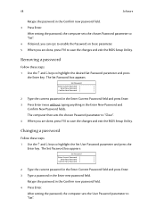
..., press F10 to save the changes and exit the BIOS Setup Utility. Removing a password Follow these steps: 1 Use the ↑ and ↓ keys to highlight the desired Set Password parameter and press the Enter key. Retype the password in the Confirm new password field. 3 Press Enter. After setting the password, the computer sets the User Password parameter to save the changes and exit the BIOS Setup Utility. 68 Software Retype the password in the Confirm new password field. 4 Press...
..., press F10 to save the changes and exit the BIOS Setup Utility. Removing a password Follow these steps: 1 Use the ↑ and ↓ keys to highlight the desired Set Password parameter and press the Enter key. Retype the password in the Confirm new password field. 3 Press Enter. After setting the password, the computer sets the User Password parameter to save the changes and exit the BIOS Setup Utility. 68 Software Retype the password in the Confirm new password field. 4 Press...
Aspire 1400 User Guide
Page 85
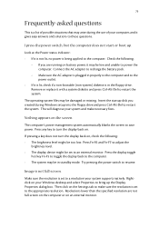
... operating system files may arise during Windows setup into the floppy drive and press Ctrl-Alt-Del to an external monitor. Insert the startup disk you are not full-screen on the computer or on the screen. I press the power switch, but the computer does not start or boot-up the Display Properties dialog box. Make sure the resolution is not full-screen. Press any key to turn the display...
... operating system files may arise during Windows setup into the floppy drive and press Ctrl-Alt-Del to an external monitor. Insert the startup disk you are not full-screen on the computer or on the screen. I press the power switch, but the computer does not start or boot-up the Display Properties dialog box. Make sure the resolution is not full-screen. Press any key to turn the display...
Aspire 1400 User Guide
Page 108
... year 2000 compliance 95 num lock 14 on indicator 12 numeric keypad embedded 15 O optical drive 22 options hard disk upgrade 50 memory upgrade 49 PC Cards 46 spare AC adapter 48 spare battery 48 P palm rest 18 parallel port setting in BIOS Utility 66 password 29 changing 68 removing 68 setting 67 PC Card ejecting 47 inserting 46 ports AC adapter 7 external display 7 microphone 5 modem jack 7 network jack 7 parallel 7 speaker/headphone 5 USB 7 video-out 7 power management 38 printer connecting 44 troubleshooting 77 problems 75 audio 76
... year 2000 compliance 95 num lock 14 on indicator 12 numeric keypad embedded 15 O optical drive 22 options hard disk upgrade 50 memory upgrade 49 PC Cards 46 spare AC adapter 48 spare battery 48 P palm rest 18 parallel port setting in BIOS Utility 66 password 29 changing 68 removing 68 setting 67 PC Card ejecting 47 inserting 46 ports AC adapter 7 external display 7 microphone 5 modem jack 7 network jack 7 parallel 7 speaker/headphone 5 USB 7 video-out 7 power management 38 printer connecting 44 troubleshooting 77 problems 75 audio 76


