
AL1916e Service Guide
Page 5
..., uses and can be used in order to comply with the emission limits. 3. Reorient or relocate the receiving antenna. 2. NOTICE: 1. Shielded interface cables and AC power cord, if any radio or TV interference caused by unauthorized modification to this equipment. If this equipment does cause harmful interference to radio or television...
..., uses and can be used in order to comply with the emission limits. 3. Reorient or relocate the receiving antenna. 2. NOTICE: 1. Shielded interface cables and AC power cord, if any radio or TV interference caused by unauthorized modification to this equipment. If this equipment does cause harmful interference to radio or television...
AL1916e Service Guide
Page 6
... service personnel. Do not place the monitor on an unstable trolley, stand, or table. To ensure reliable operation of power supplied to the appliance. l Do not overload power strips and extension cords. l Slots and openings in a bookcase or cabinet unless proper ventilation is equipped with a three...between 100-240V AC, Min. 3.5A. Please refer all servicing to service the monitor yourself; l Never push any object into a grounded power outlet as a safety feature. Do not place the monitor in the back and bottom of the grounded plug. opening or removing covers can ...
... service personnel. Do not place the monitor on an unstable trolley, stand, or table. To ensure reliable operation of power supplied to the appliance. l Do not overload power strips and extension cords. l Slots and openings in a bookcase or cabinet unless proper ventilation is equipped with a three...between 100-240V AC, Min. 3.5A. Please refer all servicing to service the monitor yourself; l Never push any object into a grounded power outlet as a safety feature. Do not place the monitor in the back and bottom of the grounded plug. opening or removing covers can ...
AL1916e Service Guide
Page 7
... switching the image, when the same image is recovered slowly by changing the image or turning off the Power Switch and then turn it on the desktop pattern you use . Turn off the Power Switch for hours. l Due to the nature of the LCD screen, an afterimage of 99.99% or more...
... switching the image, when the same image is recovered slowly by changing the image or turning off the Power Switch and then turn it on the desktop pattern you use . Turn off the Power Switch for hours. l Due to the nature of the LCD screen, an afterimage of 99.99% or more...
AL1916e Service Guide
Page 8
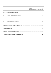
Table of contents Chapter 1 MONITOR FEATURE 9 Chapter 2 OPERATING INSTRUTION 16 Chapter 3 MACHINE ASSEMBLY 21 Chapter 4 TROUBLE SHOOTING 32 Chapter 5 CONNECTOR INFORMATION 34 Chapter 6 FRU LIST 35 Chapter 7 SCHEMATIC DIAGRAM 36 Chapter 8 POWER BOARD INFORMATION 40 - 8 -
Table of contents Chapter 1 MONITOR FEATURE 9 Chapter 2 OPERATING INSTRUTION 16 Chapter 3 MACHINE ASSEMBLY 21 Chapter 4 TROUBLE SHOOTING 32 Chapter 5 CONNECTOR INFORMATION 34 Chapter 6 FRU LIST 35 Chapter 7 SCHEMATIC DIAGRAM 36 Chapter 8 POWER BOARD INFORMATION 40 - 8 -
AL1916e Service Guide
Page 9
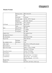
... Panel Input Display Color Maximum Dot Clock ® Max Resolution Plug & Play EPA ENERGY STAY Audio output Input Connector Input Video Signal Screen Size (Active) Power Source Environmental Considerations Weight (N.W.) Dimension Driving system Size Pixel pitch Viewable angle Brightness Contrast Ratio Response time Video Separate Sync H-Frequency V-Frequency ON Mode OFF...
... Panel Input Display Color Maximum Dot Clock ® Max Resolution Plug & Play EPA ENERGY STAY Audio output Input Connector Input Video Signal Screen Size (Active) Power Source Environmental Considerations Weight (N.W.) Dimension Driving system Size Pixel pitch Viewable angle Brightness Contrast Ratio Response time Video Separate Sync H-Frequency V-Frequency ON Mode OFF...

AL1916e Service Guide
Page 10
Switch * Power Switch * MENU / EXIT * / Volume * / Volume * AUTO / ENTER External Controls : Regulatory Compliance * Contrast/brightness * Focus * Clock * H.Position * W.Position * Language * OSD Color temperature * OSD Position & Timeout * Auto Config * Input * Information * Reset * Exit cUL, FCC, TUV, CE, ISO13406-2 - 10 -
Switch * Power Switch * MENU / EXIT * / Volume * / Volume * AUTO / ENTER External Controls : Regulatory Compliance * Contrast/brightness * Focus * Clock * H.Position * W.Position * Language * OSD Color temperature * OSD Position & Timeout * Auto Config * Input * Information * Reset * Exit cUL, FCC, TUV, CE, ISO13406-2 - 10 -
AL1916e Service Guide
Page 16
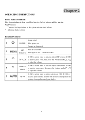
... or MINUS to view OSD. Key Definition: There are five keys defined in this system and described bellows. * Adjusting display settings External Controls Power on/off ?1 POWER Blue: power on Orange: in OSD. OPERATING INSTRUCTIONS Chapter 2 Front Panel Definition This Section defines the front panel User Interface for Led Indictor and Key function...
... or MINUS to view OSD. Key Definition: There are five keys defined in this system and described bellows. * Adjusting display settings External Controls Power on/off ?1 POWER Blue: power on Orange: in OSD. OPERATING INSTRUCTIONS Chapter 2 Front Panel Definition This Section defines the front panel User Interface for Led Indictor and Key function...

AL1916e Service Guide
Page 19
... system status and defined as bellows : LED Color Blue System Status System in normal operation mode Amber System in power-saving mode Dark System in power-off mode LOGO : When the monitor is power on the level of its display capabilities. The communication channel is a bi-directional data channel based on the I2C...
... system status and defined as bellows : LED Color Blue System Status System in normal operation mode Amber System in power-saving mode Dark System in power-off mode LOGO : When the monitor is power on the level of its display capabilities. The communication channel is a bi-directional data channel based on the I2C...

AL1916e Service Guide
Page 20
... with a grounding type attachment plug, rated 10A, 250V,CEE-22 male configuration. This feature is designed to conserve electrical energy by reducing power consumption when there is no video-input signal present. When there is no video input signal this monitor, following a time-out period, ... molded-on the keyboard, or clicking the mouse. USING THE RIGHT POWER CORD The accessory power cord for the Northern American region is similar to power outlet of personal computer: Please use VDE 0602, 0625, 0821 approval power cord in European counties. - 20 - One end terminates with units ...
... with a grounding type attachment plug, rated 10A, 250V,CEE-22 male configuration. This feature is designed to conserve electrical energy by reducing power consumption when there is no video-input signal present. When there is no video input signal this monitor, following a time-out period, ... molded-on the keyboard, or clicking the mouse. USING THE RIGHT POWER CORD The accessory power cord for the Northern American region is similar to power outlet of personal computer: Please use VDE 0602, 0625, 0821 approval power cord in European counties. - 20 - One end terminates with units ...

AL1916e Service Guide
Page 24
2 1 3 4 5 1 2 1.[GET POWER/B] 2.[INSERT JUMPER IN THE APPOINTED PLACE OF JP10 AT POWER/B] 3.[GET AGGLUTINANT TO CONNECT THE JUMPER AND POWER/B] 4 .[MARK DOT IN THE PANE MARK OF POWER/B AS PICTURE SHOWS] 5. [ASSEMBLE POWER/B THAT IS OK IN THE SHIELDING] 1.[FASTEN 3*PCS SCREW(M3*6-B) IN P/B] 2.[FASTEN 3*PCS SCREW(M3*6-B) IN M/B] - 24 -
2 1 3 4 5 1 2 1.[GET POWER/B] 2.[INSERT JUMPER IN THE APPOINTED PLACE OF JP10 AT POWER/B] 3.[GET AGGLUTINANT TO CONNECT THE JUMPER AND POWER/B] 4 .[MARK DOT IN THE PANE MARK OF POWER/B AS PICTURE SHOWS] 5. [ASSEMBLE POWER/B THAT IS OK IN THE SHIELDING] 1.[FASTEN 3*PCS SCREW(M3*6-B) IN P/B] 2.[FASTEN 3*PCS SCREW(M3*6-B) IN M/B] - 24 -
AL1916e Service Guide
Page 25
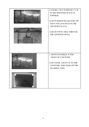
1.[FASTEN 1*PCS SCREW(M3.5*8-B) IN THE APPOINTED PLACE OF POWER/B] 2.[GET POWER/B MYLAR,TEAR OFF BACK TYPE AND STICK ON THE APPOINTED PLACE] 3.[GET BUTTON CABLE THROUGH THE APPOINTED HOLE] 1. [MOVE PCB SHIELD TOTHE FRONT OF CONVEYER] 2 [GET PANEL AND PUT IT ON THE CONVEYER, THEN TEAR OFF THE INCOMING TAPE] - 25 -
1.[FASTEN 1*PCS SCREW(M3.5*8-B) IN THE APPOINTED PLACE OF POWER/B] 2.[GET POWER/B MYLAR,TEAR OFF BACK TYPE AND STICK ON THE APPOINTED PLACE] 3.[GET BUTTON CABLE THROUGH THE APPOINTED HOLE] 1. [MOVE PCB SHIELD TOTHE FRONT OF CONVEYER] 2 [GET PANEL AND PUT IT ON THE CONVEYER, THEN TEAR OFF THE INCOMING TAPE] - 25 -
AL1916e Service Guide
Page 27
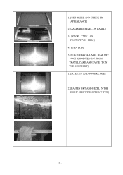
1. [GET BEZEL AND CHECK ITS APPEARANCE] 2 .[ASSEMBLE BEZEL ON PANEL] 3. [STICK TYPE ON PROTECTIVE FILM] 4.[TURN LCD] 5.[FETCH TRAVEL CARD, TEAR OFF 1*PCS APPOINTED S/N FROM TRAVEL CARD AND PASTE IT ON THE RIGHT BKT] 1. [SCAN S/N AND POWER CODE] 2. [FASTEN BKT AND BEZEL IN THE RIGHT SIDE WITH SCREW 3*PCS ] - 27 -
1. [GET BEZEL AND CHECK ITS APPEARANCE] 2 .[ASSEMBLE BEZEL ON PANEL] 3. [STICK TYPE ON PROTECTIVE FILM] 4.[TURN LCD] 5.[FETCH TRAVEL CARD, TEAR OFF 1*PCS APPOINTED S/N FROM TRAVEL CARD AND PASTE IT ON THE RIGHT BKT] 1. [SCAN S/N AND POWER CODE] 2. [FASTEN BKT AND BEZEL IN THE RIGHT SIDE WITH SCREW 3*PCS ] - 27 -

AL1916e Service Guide
Page 28
1.[FASTEN BKT AND BEZEL IN THE RIGHT SIDE WITH SCREW 3*PCS ] 2.[SCAN S/N AND POWER CODE] 1.[GET SHIELD ON THE BKT R/L] 2. [INSERT LCD CABLE INTO PANEL CONNECTOR] 3. [STICK 1*PCS YELLOW TAPE TO FASTEN LCD CABLE] 4. [TRIM WIRES AND ASSEMBLE SHIELDING IN RIGHT POSITION] - 28 -
1.[FASTEN BKT AND BEZEL IN THE RIGHT SIDE WITH SCREW 3*PCS ] 2.[SCAN S/N AND POWER CODE] 1.[GET SHIELD ON THE BKT R/L] 2. [INSERT LCD CABLE INTO PANEL CONNECTOR] 3. [STICK 1*PCS YELLOW TAPE TO FASTEN LCD CABLE] 4. [TRIM WIRES AND ASSEMBLE SHIELDING IN RIGHT POSITION] - 28 -

AL1916e Service Guide
Page 29
1. [LOCK 4*PCS SCREW(M3*3-I) TO FASTEN PCB SHIELD] 1.[FETCH BUTTON AND PUT IT IN THE MIDDLE OF CONVEYER] 2.[FASTEN 2*PCS IO-NUT IN THE M/B] 3.[INSERT UPPER CCFT CABLE IN POWER/B] 1.[FETCH BUTTON&ITS CABLE,THEN ASSEMBLE THEM] 2.[ASSEMBLE BUTTON/B AND BEZEL] 3.[LOCK 3*PCS SCREW(F3*8-I) TO FASTEN BUTTON/B ON THE BEZEL] 4.[STICK 1*PCS AL FOIL TO COVER UPPER CCFT CABLE] - 29 -
1. [LOCK 4*PCS SCREW(M3*3-I) TO FASTEN PCB SHIELD] 1.[FETCH BUTTON AND PUT IT IN THE MIDDLE OF CONVEYER] 2.[FASTEN 2*PCS IO-NUT IN THE M/B] 3.[INSERT UPPER CCFT CABLE IN POWER/B] 1.[FETCH BUTTON&ITS CABLE,THEN ASSEMBLE THEM] 2.[ASSEMBLE BUTTON/B AND BEZEL] 3.[LOCK 3*PCS SCREW(F3*8-I) TO FASTEN BUTTON/B ON THE BEZEL] 4.[STICK 1*PCS AL FOIL TO COVER UPPER CCFT CABLE] - 29 -

AL1916e Service Guide
Page 30
1.[PASTE YELLOW TAPE TO FASTEN BUTTON/B CABLE] 2.[INSERT LOWER CCFT CABLE IN POWER/B] 3.[STICK 1*PCS AL FOIL TO COVER UPPER CCFT CABLE] 1.[GET LCD COVER AND INSPECT ITS APPEARANCE] 2.[ASSEMBLE LCD COVER TO BEZEL] 1.[FETCH TRAVEL CARD, TEAR OFF 1*PCS APPOINTED S/N FROM TRAVEL CARD AND PASTE IT ON THE COVER] 2.[LOCK 2*PCS SCREW (F3*8-B) TO FASTEN BE ZEL AND LCD COVER] - 30 -
1.[PASTE YELLOW TAPE TO FASTEN BUTTON/B CABLE] 2.[INSERT LOWER CCFT CABLE IN POWER/B] 3.[STICK 1*PCS AL FOIL TO COVER UPPER CCFT CABLE] 1.[GET LCD COVER AND INSPECT ITS APPEARANCE] 2.[ASSEMBLE LCD COVER TO BEZEL] 1.[FETCH TRAVEL CARD, TEAR OFF 1*PCS APPOINTED S/N FROM TRAVEL CARD AND PASTE IT ON THE COVER] 2.[LOCK 2*PCS SCREW (F3*8-B) TO FASTEN BE ZEL AND LCD COVER] - 30 -

AL1916e Service Guide
Page 32
OK Check Power Button From Scalar/B(CN6) to Button/B(CN1) NO Change Scalar Module Board NO Check Cable Yes Open ? No Power No Power Check Power Board Output CN4 Pin 5,Pin6 =5V NO Change Adaptor Power Board OK Check Scalar Module Output R96 =5V? R98 = 1.8V ? Change Cable NO Change Switch or Button Board - 32 - R99 = 3.3V ? Chapter 4 TROUBLE SHOOTING This chapter provides trouble shooting information forAL1916 1.
OK Check Power Button From Scalar/B(CN6) to Button/B(CN1) NO Change Scalar Module Board NO Check Cable Yes Open ? No Power No Power Check Power Board Output CN4 Pin 5,Pin6 =5V NO Change Adaptor Power Board OK Check Scalar Module Output R96 =5V? R98 = 1.8V ? Change Cable NO Change Switch or Button Board - 32 - R99 = 3.3V ? Chapter 4 TROUBLE SHOOTING This chapter provides trouble shooting information forAL1916 1.

AL1916e Service Guide
Page 40
Power Board Information Panel P/N AAM190EN129(AU) AA0190EA108(CPT) Description Chapter 8 Current Type Value P/B P/N AS05B312D00 AS05B520207 Description ADP/INV,FSP043-2PI01 90~264V GP ADP/INV,SLS0532D0248,90~264V,REV1A GP When the lamp current value is 7.0mA, the jumper should be done as the picture left shows - - 40 -
Power Board Information Panel P/N AAM190EN129(AU) AA0190EA108(CPT) Description Chapter 8 Current Type Value P/B P/N AS05B312D00 AS05B520207 Description ADP/INV,FSP043-2PI01 90~264V GP ADP/INV,SLS0532D0248,90~264V,REV1A GP When the lamp current value is 7.0mA, the jumper should be done as the picture left shows - - 40 -
AL1916p Service Guide
Page 5
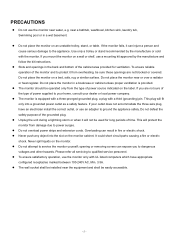
...not blocked or covered. If you to protect it will protect the monitor from overheating, be easily accessible. - 5 - z Do not overload power strips and extension cords. z Do not attempt to qualified service personnel. Use only a trolley or stand recommended by the manufacture and follow the ...kit instructions. Do not place the monitor in a wet basement. z Never push any object into a grounded power outlet as a safety feature. PRECAUTIONS z Do not use the monitor only with UL listed computers which have an electrician install the correct outlet...
...not blocked or covered. If you to protect it will protect the monitor from overheating, be easily accessible. - 5 - z Do not overload power strips and extension cords. z Do not attempt to qualified service personnel. Use only a trolley or stand recommended by the manufacture and follow the ...kit instructions. Do not place the monitor in a wet basement. z Never push any object into a grounded power outlet as a safety feature. PRECAUTIONS z Do not use the monitor only with UL listed computers which have an electrician install the correct outlet...
AL1916p Service Guide
Page 6
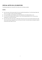
Turn off the Power Switch for hours. SPECIAL NOTES ON LCD MONITORS The following symptoms are normal with LCD monitor and do not indicate a problem. z You may flicker during ...initial use . It may remain after switching the image, when the same image is recovered slowly by changing the image or turning off the Power Switch and then turn it on the desktop pattern you use . In this case, the screen is displayed for hours. - 6 - z Due to the nature of...
Turn off the Power Switch for hours. SPECIAL NOTES ON LCD MONITORS The following symptoms are normal with LCD monitor and do not indicate a problem. z You may flicker during ...initial use . It may remain after switching the image, when the same image is recovered slowly by changing the image or turning off the Power Switch and then turn it on the desktop pattern you use . In this case, the screen is displayed for hours. - 6 - z Due to the nature of...
AL1916p Service Guide
Page 7
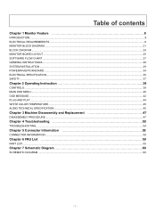
... Feature 8 INTRODUCTION...8 ELECTRICAL REQUIREMEENTS...9 MONITOR BLOCK DIAGRAM ...21 BLOCK DIAGRAM ...24 MONITOR BOARD LAYOUT ...25 SOFTWARE FLOW CHART ...27 GENERAL INSTRUCTIONS ...28 SYSTEM INSTALLATION ...29 POWER/INVERTOR BOARD ...34 ELECTRICAL SPECIFICATION...35 SAFETY ...37 Chapter 2 Operating Instruction 39 CONTROLS ...39 MAIN OSD MENU ...40 OSD MESSAGE...42 PLUG AND PLAY ...44...
... Feature 8 INTRODUCTION...8 ELECTRICAL REQUIREMEENTS...9 MONITOR BLOCK DIAGRAM ...21 BLOCK DIAGRAM ...24 MONITOR BOARD LAYOUT ...25 SOFTWARE FLOW CHART ...27 GENERAL INSTRUCTIONS ...28 SYSTEM INSTALLATION ...29 POWER/INVERTOR BOARD ...34 ELECTRICAL SPECIFICATION...35 SAFETY ...37 Chapter 2 Operating Instruction 39 CONTROLS ...39 MAIN OSD MENU ...40 OSD MESSAGE...42 PLUG AND PLAY ...44...


