
AL1712 Service Guide
Page 7
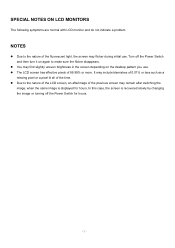
It may flicker during initial use . Due to the nature of the LCD screen, an afterimage of the previous screen may find slightly uneven brightness in the screen depending on again to the nature of the fluorescent light, ... then turn it on the desktop pattern you use . In this case, the screen is displayed for hours. - 7 - SPECIAL NOTES ON LCD MONITORS The following symptoms are normal with LCD monitor and do not indicate a problem. Turn off the Power Switch for hours. NOTES Due to make sure the flicker disappears. The...
It may flicker during initial use . Due to the nature of the LCD screen, an afterimage of the previous screen may find slightly uneven brightness in the screen depending on again to the nature of the fluorescent light, ... then turn it on the desktop pattern you use . In this case, the screen is displayed for hours. - 7 - SPECIAL NOTES ON LCD MONITORS The following symptoms are normal with LCD monitor and do not indicate a problem. Turn off the Power Switch for hours. NOTES Due to make sure the flicker disappears. The...
AL1712 Service Guide
Page 8
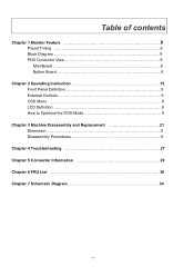
Table of contents Chapter 1 Monitor Feature 9 Preset Timing 9 Block Diagram 9 PCB Conductor View 9 MainBoard 9 Button Board 9 Chapter 2 Operating Instruction 15 Front Panel Definition 9 External Controls 9 OSD Menu 9 LCD Definition 9 How to Optimize the DOS-Mode 9 Chapter 3 Machine Disassembly and Replacement 21 Dimension 9 Disassembly Procedures 9 Chapter 4 Troubleshooting 27 Chapter 5 Connector Information 29 Chapter 6 FRU List 30 Chapter 7 Schematic Diagram 34 - 8 -
Table of contents Chapter 1 Monitor Feature 9 Preset Timing 9 Block Diagram 9 PCB Conductor View 9 MainBoard 9 Button Board 9 Chapter 2 Operating Instruction 15 Front Panel Definition 9 External Controls 9 OSD Menu 9 LCD Definition 9 How to Optimize the DOS-Mode 9 Chapter 3 Machine Disassembly and Replacement 21 Dimension 9 Disassembly Procedures 9 Chapter 4 Troubleshooting 27 Chapter 5 Connector Information 29 Chapter 6 FRU List 30 Chapter 7 Schematic Diagram 34 - 8 -
AL1712 Service Guide
Page 9
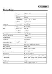
Monitor Feature Chapter 1 LCD Panel Input Display Color Maximum Dot Clock ® Max Resolution Plug & Play EPA ENERGY STAY Audio output Input Connector Input Video Signal Maximum Screen Size Power Source Environmental Considerations Weight (N.W.) Dimension Driving system Size Pixel pitch Viewable angle Brightness Contrast Ratio Response time Video Separate Sync H-Frequency V-Frequency ON Mode OFF Mode TFT Color LCD 17" 0.264 mm 150(H) x 125 (V) degree 300 cd/m2(typ) 450:1 (typ) 20ms (Tr+Tf) R,G,B Analog H/V TTL 31-81KHZ 56-75HZ 16.2 million Colors 135MHz 1280x1024@75HZ VESA DDC2B
Monitor Feature Chapter 1 LCD Panel Input Display Color Maximum Dot Clock ® Max Resolution Plug & Play EPA ENERGY STAY Audio output Input Connector Input Video Signal Maximum Screen Size Power Source Environmental Considerations Weight (N.W.) Dimension Driving system Size Pixel pitch Viewable angle Brightness Contrast Ratio Response time Video Separate Sync H-Frequency V-Frequency ON Mode OFF Mode TFT Color LCD 17" 0.264 mm 150(H) x 125 (V) degree 300 cd/m2(typ) 450:1 (typ) 20ms (Tr+Tf) R,G,B Analog H/V TTL 31-81KHZ 56-75HZ 16.2 million Colors 135MHz 1280x1024@75HZ VESA DDC2B
AL1712 Service Guide
Page 24
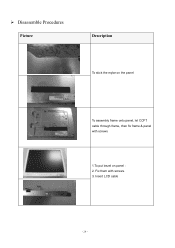
Fix them with screws 1.To put bezel on the panel To assembly frame onto panel, let CCFT cable through frame, then fix frame & panel with screws. 3. Insert LCD cable - 24 - Disassemble Procedures Picture Description To stick the mylar on panel : 2.
Fix them with screws 1.To put bezel on the panel To assembly frame onto panel, let CCFT cable through frame, then fix frame & panel with screws. 3. Insert LCD cable - 24 - Disassemble Procedures Picture Description To stick the mylar on panel : 2.

AL1712 Service Guide
Page 25
Stick mylar on power BD shielding Assemble main BD & power BD on the frame with screw - 25 - Insert CCFL cable into main BD. Fix button BD & bezel with screws Insert LCD cable into power BD.
Stick mylar on power BD shielding Assemble main BD & power BD on the frame with screw - 25 - Insert CCFL cable into main BD. Fix button BD & bezel with screws Insert LCD cable into power BD.

AL1712 Service Guide
Page 33
L7T LCD COVER SUB 14 LCD COVER ASSY 60.L13VE.005 ASSY 15 STAND BASE ASSY L7T STAND BASE ASSY 60.L13VE.007 16 STAND NECK ASSY L7T STAND ASSY 60.L13VE.009 17 HINGE CAP HIGNE CAP L7T 42.L13VE.001 18 POWER BOARD ESD L7T POWER-BD-ESD 33.L13VE.001 19 LCD FRAME L7T FRAME 33.L13VE.002 SPEAKER ASSY L7T 20 SPEAKER 23.L23VE.001 FG-QT390E 1.5WX2 - 33 -
L7T LCD COVER SUB 14 LCD COVER ASSY 60.L13VE.005 ASSY 15 STAND BASE ASSY L7T STAND BASE ASSY 60.L13VE.007 16 STAND NECK ASSY L7T STAND ASSY 60.L13VE.009 17 HINGE CAP HIGNE CAP L7T 42.L13VE.001 18 POWER BOARD ESD L7T POWER-BD-ESD 33.L13VE.001 19 LCD FRAME L7T FRAME 33.L13VE.002 SPEAKER ASSY L7T 20 SPEAKER 23.L23VE.001 FG-QT390E 1.5WX2 - 33 -


