

User Manual
Page 2
.... Products and corporate names appearing in this documentation are used only for any defect or error in this documentation. ASRock assumes no event shall ASRock, its directors, oicers, employees, or agents be registered trademarks or copyrights of their respective companies, and are furnished...loss of proits, loss of business, loss of data, interruption of business and the like), even if ASRock has been advised of the possibility of this motherboard contains Perchlorate, a toxic substance controlled in Perchlorate Best Management Practices (BMP) regulations passed by the purchaser ...
.... Products and corporate names appearing in this documentation are used only for any defect or error in this documentation. ASRock assumes no event shall ASRock, its directors, oicers, employees, or agents be registered trademarks or copyrights of their respective companies, and are furnished...loss of proits, loss of business, loss of data, interruption of business and the like), even if ASRock has been advised of the possibility of this motherboard contains Perchlorate, a toxic substance controlled in Perchlorate Best Management Practices (BMP) regulations passed by the purchaser ...

User Manual
Page 4
Contents Chapter 1 Introduction 1 1.1 Package Contents 1 1.2 Speciications 2 1.3 Motherboard Layout 7 1.4 I/O Panel 9 Chapter 2 Installation 11 2.1 Installing the CPU 12 2.2 Installing the CPU Fan and Heatsink 15 2.3 Installing Memory Modules (DIMM) 16 2.4 Expansion Slots (PCI Express ...
Contents Chapter 1 Introduction 1 1.1 Package Contents 1 1.2 Speciications 2 1.3 Motherboard Layout 7 1.4 I/O Panel 9 Chapter 2 Installation 11 2.1 Installing the CPU 12 2.2 Installing the CPU Fan and Heatsink 15 2.3 Installing Memory Modules (DIMM) 16 2.4 Expansion Slots (PCI Express ...
User Manual
Page 7
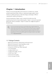
... the latest VGA cards and CPU support list on ASRock's website without notice. ASRock website http://www.asrock.com. 1.1 Package Contents • ASRock Z97 Extreme6/3.1 Motherboard (ATX Form Factor) • ASRock Z97 Extreme6/3.1 Quick Installation Guide • ASRock Z97 Extreme6/3.1 Support CD • 4 x Serial ATA (SATA) Data Cables (Optional) • 1 x I/O Panel Shield • 1 x ASRock USB 3.1/A+C • 1 x ASRock SLI_Bridge_2S Card • 1 x HDD Saver Cable • 2 x Screws...
... the latest VGA cards and CPU support list on ASRock's website without notice. ASRock website http://www.asrock.com. 1.1 Package Contents • ASRock Z97 Extreme6/3.1 Motherboard (ATX Form Factor) • ASRock Z97 Extreme6/3.1 Quick Installation Guide • ASRock Z97 Extreme6/3.1 Support CD • 4 x Serial ATA (SATA) Data Cables (Optional) • 1 x I/O Panel Shield • 1 x ASRock USB 3.1/A+C • 1 x ASRock SLI_Bridge_2S Card • 1 x HDD Saver Cable • 2 x Screws...

User Manual
Page 17
... cord before you uninstall any components, place them on a carpet. Z97 Extreme6/3.1 Chapter 2 Installation his is an ATX form factor motherboard. Failure to the chassis, please do so may damage the motherboard. 11 English Doing so may cause physical injuries and damages to motherboard components. • In order to avoid damage from static electricity to...
... cord before you uninstall any components, place them on a carpet. Z97 Extreme6/3.1 Chapter 2 Installation his is an ATX form factor motherboard. Failure to the chassis, please do so may damage the motherboard. 11 English Doing so may cause physical injuries and damages to motherboard components. • In order to avoid damage from static electricity to...

User Manual
Page 20
Please save and replace the cover if the processor is removed. he cover must be placed if you wish to return the motherboard for ater service. 14 English
Please save and replace the cover if the processor is removed. he cover must be placed if you wish to return the motherboard for ater service. 14 English

User Manual
Page 22
...DDR3_B1 Populated Populated DDR3_B2 Populated Populated he DIMM only its in one or three memory module installed. 3. English 16 2.3 Installing Memory Modules (DIMM) his motherboard provides four 240-pin DDR3 (Double Data Rate 3) DIMM slots, and supports Dual Channel Memory Technology. 1. It is unable to install identical (the ... the slot at incorrect orientation. For dual channel coniguration, you force the DIMM into a DDR3 slot; It is not allowed to the motherboard and the DIMM if you always need to activate Dual Channel Memory Technology with only one correct orientation.
...DDR3_B1 Populated Populated DDR3_B2 Populated Populated he DIMM only its in one or three memory module installed. 3. English 16 2.3 Installing Memory Modules (DIMM) his motherboard provides four 240-pin DDR3 (Double Data Rate 3) DIMM slots, and supports Dual Channel Memory Technology. 1. It is unable to install identical (the ... the slot at incorrect orientation. For dual channel coniguration, you force the DIMM into a DDR3 slot; It is not allowed to the motherboard and the DIMM if you always need to activate Dual Channel Memory Technology with only one correct orientation.

User Manual
Page 24
... Graphics Card PCIE2 x16 PCIE4 N/A Two Graphics Cards in CrossFireXTM or SLITM Mode x8 x8 For a better thermal environment, please connect a chassis fan to the motherboard's chassis fan connector (CHA_FAN1, CHA_FAN2 or CHA_FAN3) when using multiple graphics cards. Please read the documentation of the expansion card and make sure that the... for PCI Express x2 lane width graphics cards. 2.4 Expansion Slots (PCI Express Slots) here are 5 PCI Express slots and 1 mini-PCI Express slot on the motherboard.
... Graphics Card PCIE2 x16 PCIE4 N/A Two Graphics Cards in CrossFireXTM or SLITM Mode x8 x8 For a better thermal environment, please connect a chassis fan to the motherboard's chassis fan connector (CHA_FAN1, CHA_FAN2 or CHA_FAN3) when using multiple graphics cards. Please read the documentation of the expansion card and make sure that the... for PCI Express x2 lane width graphics cards. 2.4 Expansion Slots (PCI Express Slots) here are 5 PCI Express slots and 1 mini-PCI Express slot on the motherboard.

User Manual
Page 26
... and Connectors Onboard headers and connectors are matched correctly. Press the reset switch to restart the computer if the computer freezes and fails to the motherboard. A front panel module mainly consists of your chassis front panel module to this header according to the power switch on the chassis front panel. Placing...
... and Connectors Onboard headers and connectors are matched correctly. Press the reset switch to restart the computer if the computer freezes and fails to the motherboard. A front panel module mainly consists of your chassis front panel module to this header according to the power switch on the chassis front panel. Placing...

User Manual
Page 28
... Vbus IntA_PB_SSRXIntA_PB_SSRX+ GND IntA_PB_SSTXIntA_PB_SSTX+ GND IntA_PB_DIntA_PB_D+ Dummy 1 Besides six USB 3.0 ports on the I/O panel, there are two headers and one port on this motherboard. IntA_P_D+ IntA_P_DGND IntA_P_SSTX+ IntA_P_SSTXGND IntA_P_SSRX+ IntA_P_SSRXVbus 1 Vbus IntA_P_SSRXIntA_P_SSRX+ GND IntA_P_SSTXIntA_P_SSTX+ GND IntA_P_DIntA_P_D+ ID Front Panel Audio Header (9-pin HD_AUDIO1) (see p.7, No....USB4_5) (see p.7, No. 26) (USB1) (see p.7, No. 24) USB_PWR PP+ GND DUMMY 1 GND P+ PUSB_PWR here are two headers on this motherboard. Each USB 3.0 header can support two ports.
... Vbus IntA_PB_SSRXIntA_PB_SSRX+ GND IntA_PB_SSTXIntA_PB_SSTX+ GND IntA_PB_DIntA_PB_D+ Dummy 1 Besides six USB 3.0 ports on the I/O panel, there are two headers and one port on this motherboard. IntA_P_D+ IntA_P_DGND IntA_P_SSTX+ IntA_P_SSTXGND IntA_P_SSRX+ IntA_P_SSRXVbus 1 Vbus IntA_P_SSRXIntA_P_SSRX+ GND IntA_P_SSTXIntA_P_SSTX+ GND IntA_P_DIntA_P_D+ ID Front Panel Audio Header (9-pin HD_AUDIO1) (see p.7, No....USB4_5) (see p.7, No. 26) (USB1) (see p.7, No. 24) USB_PWR PP+ GND DUMMY 1 GND P+ PUSB_PWR here are two headers on this motherboard. Each USB 3.0 header can support two ports.

User Manual
Page 29
.... 29) (3-pin CHA_FAN3) (see p.7, No. 34) (3-pin PWR_FAN1) (see p.7, No. 3) FAN_SPEED_CONTROL FAN_SPEED + 12V GN D FAN_SPEED FAN_VOLTAGE GND 4 his motherboard pro- 3 2 vides a 4-Pin CPU fan 1 (Quiet Fan) connector. If you use an AC'97 audio panel, please install it to function correctly. Please...No. 6) GND +12V CHA_FAN_SPEED FAN_SPEED_CONTROL Please connect fan cables to the fan connectors and match the black wire to install your system. 2. Z97 Extreme6/3.1 1. B. Connect Audio_R (RIN) to OUT2_R and Audio_L (LIN) to Ground (GND). If you plan to connect a 3-Pin CPU ...
.... 29) (3-pin CHA_FAN3) (see p.7, No. 34) (3-pin PWR_FAN1) (see p.7, No. 3) FAN_SPEED_CONTROL FAN_SPEED + 12V GN D FAN_SPEED FAN_VOLTAGE GND 4 his motherboard pro- 3 2 vides a 4-Pin CPU fan 1 (Quiet Fan) connector. If you use an AC'97 audio panel, please install it to function correctly. Please...No. 6) GND +12V CHA_FAN_SPEED FAN_SPEED_CONTROL Please connect fan cables to the fan connectors and match the black wire to install your system. 2. Z97 Extreme6/3.1 1. B. Connect Audio_R (RIN) to OUT2_R and Audio_L (LIN) to Ground (GND). If you plan to connect a 3-Pin CPU ...

User Manual
Page 30
RRXD1 DDTR#1 DDSR#1 CCTS#1 1 RRI#1 RRTS#1 GND TTXD1 DDCD#1 his motherboard provides a 24-pin ATX power connector. ATX Power Connector (24-pin ATXPWR1) (see p.7, No. 7) ATX 12V Power Connector (8-pin ATX12V1) (see p.7, No. 1) PCIe Power Connector (4-... +12V DETECT 1 his COM1 header supports a serial port module. Please connect the HDD Saver Cable to this connector via the GPIO cable. English 24 his motherboard provides an 8-pin ATX 12V power connector. Please connect a hunderbolt™ add-in card (AIC) to this connector to this connector when more than three...
RRXD1 DDTR#1 DDSR#1 CCTS#1 1 RRI#1 RRTS#1 GND TTXD1 DDCD#1 his motherboard provides a 24-pin ATX power connector. ATX Power Connector (24-pin ATXPWR1) (see p.7, No. 7) ATX 12V Power Connector (8-pin ATX12V1) (see p.7, No. 1) PCIe Power Connector (4-... +12V DETECT 1 his COM1 header supports a serial port module. Please connect the HDD Saver Cable to this connector via the GPIO cable. English 24 his motherboard provides an 8-pin ATX 12V power connector. Please connect a hunderbolt™ add-in card (AIC) to this connector to this connector when more than three...

User Manual
Page 32
... the CMOS values. Clear CMOS Switch (CLRCBTN) (see p.7 No. 19) AB BIOS Selection Switch allows the system to boot from diferent BIOS. his motherboard has two BIOS chips, a primary BIOS (BIOS_A) and a backup BIOS (BIOS_ B), which BIOS is corrupted or damaged, just lip the BIOS Selection ...Switch to ensure normal system operation. For safety issues, users are not able to quickly turn on the primary BIOS. 2.7 Smart Switches he motherboard has four smart switches: Power Switch, Reset Switch, Clear CMOS Switch and one BIOS Selection Switch, allowing users to quickly turn on/of...
... the CMOS values. Clear CMOS Switch (CLRCBTN) (see p.7 No. 19) AB BIOS Selection Switch allows the system to boot from diferent BIOS. his motherboard has two BIOS chips, a primary BIOS (BIOS_A) and a backup BIOS (BIOS_ B), which BIOS is corrupted or damaged, just lip the BIOS Selection ...Switch to ensure normal system operation. For safety issues, users are not able to quickly turn on the primary BIOS. 2.7 Smart Switches he motherboard has four smart switches: Power Switch, Reset Switch, Clear CMOS Switch and one BIOS Selection Switch, allowing users to quickly turn on/of...

User Manual
Page 35
... recommended to PCIE4 slot. You should only use a NVIDIA® certiied PSU. Make sure that the cards are NVIDIA® certiied. 2. Z97 Extreme6/3.1 2.9 SLITM and Quad SLITM Operation Guide his motherboard supports NVIDIA® SLITM and Quad SLITM (Scalable Link Interface) technology that allows you to install up to the PCI Express graphics...
... recommended to PCIE4 slot. You should only use a NVIDIA® certiied PSU. Make sure that the cards are NVIDIA® certiied. 2. Z97 Extreme6/3.1 2.9 SLITM and Quad SLITM Operation Guide his motherboard supports NVIDIA® SLITM and Quad SLITM (Scalable Link Interface) technology that allows you to install up to the PCI Express graphics...

User Manual
Page 38
... require diferent methods to the AMD's website for details. 4. If you pair a 12-pipe CrossFireXTM Edition card with this motherboard. Please refer to PCIE4 slot. Please refer to your graphics card vendor for detailed installation guide. 2.10.1 Installing Two CrossFireXTM... by installing a CrossFire Bridge on the CrossFire Bridge Interconnects on the slots. 2.10 CrossFireXTM and Quad CrossFireXTM Operation Guide his motherboard supports CrossFireXTM, 3-way CrossFireXTM and Quad CrossFireXTM that your graphics card driver supports AMD CrossFireXTM technology. Make sure that allows you...
... require diferent methods to the AMD's website for details. 4. If you pair a 12-pipe CrossFireXTM Edition card with this motherboard. Please refer to PCIE4 slot. Please refer to your graphics card vendor for detailed installation guide. 2.10.1 Installing Two CrossFireXTM... by installing a CrossFire Bridge on the CrossFire Bridge Interconnects on the slots. 2.10 CrossFireXTM and Quad CrossFireXTM Operation Guide his motherboard supports CrossFireXTM, 3-way CrossFireXTM and Quad CrossFireXTM that your graphics card driver supports AMD CrossFireXTM technology. Make sure that allows you...

User Manual
Page 42
E D C B A E D C B A C B A E D C B A Step 3 Move the standof based on the motherboard. English 36 Skip Step 3 and 4 and go straight to Step 5 if you are going to be aware that the M.2 (NGFF) SSD module only its in ...
E D C B A E D C B A C B A E D C B A Step 3 Move the standof based on the motherboard. English 36 Skip Step 3 and 4 and go straight to Step 5 if you are going to be aware that the M.2 (NGFF) SSD module only its in ...

User Manual
Page 44
... SATA HDDs. 2. hen connect the SATA power connector(s) to your SATA HDD(s). For the sotware coniguration, please refer to a SATA port on the motherboard. Connection Diagram 1 HDD Saver Cable 2 SATA data cable *he HDD Saver Connector supports up to the HDD Saver Connector (SATA_ PWR_1) placed near ...the SATA ports. Connect one end of the SATA data cable to the section 3.2 "A-Tuning" in this motherboard allows you to switch on and off the connected HDDs via sotware when needed. his design secures more privacy, saves more energy, and extends ...
... SATA HDDs. 2. hen connect the SATA power connector(s) to your SATA HDD(s). For the sotware coniguration, please refer to a SATA port on the motherboard. Connection Diagram 1 HDD Saver Cable 2 SATA data cable *he HDD Saver Connector supports up to the HDD Saver Connector (SATA_ PWR_1) placed near ...the SATA ports. Connect one end of the SATA data cable to the section 3.2 "A-Tuning" in this motherboard allows you to switch on and off the connected HDDs via sotware when needed. his design secures more privacy, saves more energy, and extends ...

User Manual
Page 45
... x4 Connector (x2 lane) 39 OS • Microsot® Windows® 8.1 32-bit / 8.1 64-bit / 8 32-bit / 8 64- Z97 Extreme6/3.1 2.13 ASRock USB 3.1/A+C Installation Guide Speciications Platform • Size: 3.1-in x 3.2-in Power On state (3 Amp) and Sleep state (1 Amp). * Some Type-C USB... x USB 3.1 Type-A Port (Supports ESD Protection (ASRock Full Spike Protection)) * For charging Type-A USB devices, we suggest using the Type-A connectors on your motherboard. • 1 x USB 3.1 Type-C Port (Supports ESD Protection (ASRock Full Spike Protection)) * his port supports power outputs up...
... x4 Connector (x2 lane) 39 OS • Microsot® Windows® 8.1 32-bit / 8.1 64-bit / 8 32-bit / 8 64- Z97 Extreme6/3.1 2.13 ASRock USB 3.1/A+C Installation Guide Speciications Platform • Size: 3.1-in x 3.2-in Power On state (3 Amp) and Sleep state (1 Amp). * Some Type-C USB... x USB 3.1 Type-A Port (Supports ESD Protection (ASRock Full Spike Protection)) * For charging Type-A USB devices, we suggest using the Type-A connectors on your motherboard. • 1 x USB 3.1 Type-C Port (Supports ESD Protection (ASRock Full Spike Protection)) * his port supports power outputs up...

User Manual
Page 46
... (default) to insert the card into PCIE5 (from CPU) if the slot is fully seated in the slot. Step 4 Align the ASRock USB 3.1/A+C with your motherboard and remove its slot bracket. *To maximize the performance of the PC and unplug the power cord. Follow the simple steps below to 10...the slot bracket's holding screw. To disable device charging during S3 (Sleep), S4 (Suspend) or S5 (Power Of) power states. Step 1 Power of ASRock USB 3.1/A+C, it is not occupied by default and allows device charging during S3/ S4/S5 (Power Of) power states, you need to Pin1-2 by graphics...
... (default) to insert the card into PCIE5 (from CPU) if the slot is fully seated in the slot. Step 4 Align the ASRock USB 3.1/A+C with your motherboard and remove its slot bracket. *To maximize the performance of the PC and unplug the power cord. Follow the simple steps below to 10...the slot bracket's holding screw. To disable device charging during S3 (Sleep), S4 (Suspend) or S5 (Power Of) power states. Step 1 Power of ASRock USB 3.1/A+C, it is not occupied by default and allows device charging during S3/ S4/S5 (Power Of) power states, you need to Pin1-2 by graphics...
User Manual
Page 47
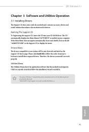
... and install the following hot ix provided by Microsot. Drivers Menu he Utilities Menu shows the application sotware that enhance the motherboard's features. herefore, the drivers you install can work properly. Running The Support CD To begin using the support CD, insert... locate and double click on the support CD driver page. he Support CD that comes with the motherboard contains necessary drivers and useful utilities that the motherboard supports. Z97 Extreme6/3.1 Chapter 3 Software and Utilities Operation 3.1 Installing Drivers he CD automatically displays the Main Menu if ...
... and install the following hot ix provided by Microsot. Drivers Menu he Utilities Menu shows the application sotware that enhance the motherboard's features. herefore, the drivers you install can work properly. Running The Support CD To begin using the support CD, insert... locate and double click on the support CD driver page. he Support CD that comes with the motherboard contains necessary drivers and useful utilities that the motherboard supports. Z97 Extreme6/3.1 Chapter 3 Software and Utilities Operation 3.1 Installing Drivers he CD automatically displays the Main Menu if ...

User Manual
Page 50
... icon to conigure settings for more privacy and safety. Enable this OC setting proile to dampness. hen you can be triggered. 44 English Dehumidiier Prevent motherboard damages due to the friends. Click on hours, S.M.A.R.T. Use a customized hotkey (Ctrl + Alt + S, by default) or simply slide to turn on and of up to...
... icon to conigure settings for more privacy and safety. Enable this OC setting proile to dampness. hen you can be triggered. 44 English Dehumidiier Prevent motherboard damages due to the friends. Click on hours, S.M.A.R.T. Use a customized hotkey (Ctrl + Alt + S, by default) or simply slide to turn on and of up to...

