
User Manual
Page 11
... access ASRock Instant Flash. ASRock motherboards are exclusively equipped with the ASRock SmartView utility that combines your most visited web sites, your history, your Facebook friends and your application's priority ideally and/or add new programs. Lower Latency in touch with your USB flash drive, floppy disk or hard drive, then you can configure your real-time newsfeed into the BIOS setup menu to get the same OC settings. LAN...
... access ASRock Instant Flash. ASRock motherboards are exclusively equipped with the ASRock SmartView utility that combines your most visited web sites, your history, your Facebook friends and your application's priority ideally and/or add new programs. Lower Latency in touch with your USB flash drive, floppy disk or hard drive, then you can configure your real-time newsfeed into the BIOS setup menu to get the same OC settings. LAN...

User Manual
Page 14
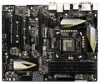
...25 24 23 22 1 Power Fan Connector (PWR_FAN1) 24 Dr. Debug 2 ATX 12V Power Connector (ATX12V1) 25 Clear CMOS Jumper (CLRCMOS1) 3 SLI / XFIRE Power Connector 26 USB 2.0 Header (USB2_3, Black) 4 Chassis Fan Connector (CHA_FAN3) 27 Intel Z77 Chipset 5 Chassis Fan Connector (CHA_FAN2) 28 USB 2.0 Header (USB4_5, Black) 6 1155-Pin CPU Socket 29 USB 2.0 Header (USB6_7, Black) 7 CPU Fan Connector (CPU_FAN1) 30 Consumer Infrared Module Header 8 CPU Fan Connector (CPU_FAN2) (CIR1, Gray) 9 2 x 240-pin DDR3 DIMM Slots 31 Front Panel IEEE 1394 Header (DDR3_A1, DDR3_B1, Black) (FRONT_1394...
...25 24 23 22 1 Power Fan Connector (PWR_FAN1) 24 Dr. Debug 2 ATX 12V Power Connector (ATX12V1) 25 Clear CMOS Jumper (CLRCMOS1) 3 SLI / XFIRE Power Connector 26 USB 2.0 Header (USB2_3, Black) 4 Chassis Fan Connector (CHA_FAN3) 27 Intel Z77 Chipset 5 Chassis Fan Connector (CHA_FAN2) 28 USB 2.0 Header (USB4_5, Black) 6 1155-Pin CPU Socket 29 USB 2.0 Header (USB6_7, Black) 7 CPU Fan Connector (CPU_FAN1) 30 Consumer Infrared Module Header 8 CPU Fan Connector (CPU_FAN2) (CIR1, Gray) 9 2 x 240-pin DDR3 DIMM Slots 31 Front Panel IEEE 1394 Header (DDR3_A1, DDR3_B1, Black) (FRONT_1394...

User Manual
Page 32
... you install two Radeon graphics cards). Step 3. For Windows® XP OS: A. Please check AMD's website for AMD driver updates. Step 4. Please check Microsoft's website for details. AMD Catalyst Control Center Step 6. Power on your computer. Restart your system. Install the VGA card drivers to uninstall any VGA drivers installed in your computer and boot into OS. We recommend using this utility to your system, and restart your Windows® taskbar. 2.8.2 Driver Installation and Setup...
... you install two Radeon graphics cards). Step 3. For Windows® XP OS: A. Please check AMD's website for AMD driver updates. Step 4. Please check Microsoft's website for details. AMD Catalyst Control Center Step 6. Power on your computer. Restart your system. Install the VGA card drivers to uninstall any VGA drivers installed in your computer and boot into OS. We recommend using this utility to your system, and restart your Windows® taskbar. 2.8.2 Driver Installation and Setup...

User Manual
Page 47
... Bridge module specific) Pre-Memory North Bridge initialization (North Bridge module specific) Pre-memory South Bridge initialization is started Pre-memory South Bridge initialization (South Bridge module specific) Pre-memory South Bridge initialization (South Bridge module specific) Pre-memory South Bridge initialization (South Bridge module specific) OEM pre-memory initialization codes Memory initialization. Boot Strap Processor (BSP) selection CPU post-memory initialization. 2.14 Dr. Debug Dr. Debug is used Power on.
... Bridge module specific) Pre-Memory North Bridge initialization (North Bridge module specific) Pre-memory South Bridge initialization is started Pre-memory South Bridge initialization (South Bridge module specific) Pre-memory South Bridge initialization (South Bridge module specific) Pre-memory South Bridge initialization (South Bridge module specific) OEM pre-memory initialization codes Memory initialization. Boot Strap Processor (BSP) selection CPU post-memory initialization. 2.14 Dr. Debug Dr. Debug is used Power on.

User Manual
Page 50
... Detect SCSI Enable Setup Verifying Password Start of Setup Reserved for ASL Setup Input Wait Reserved for ASL Ready To Boot event Legacy Boot event Exit Boot Services event Runtime Set Virtual Address MAP Begin Runtime Set Virtual Address MAP End Legacy Option ROM Initialization System Reset USB hot plug PCI bus hot plug Clean-up of NVRAM Configuration Reset (reset of the Architectural Protocols are found Invalid password Error loading Boot Option (LoadImage returned error) Boot Option is failed (StartImage returned error) Flash update is failed Reset protocol...
... Detect SCSI Enable Setup Verifying Password Start of Setup Reserved for ASL Setup Input Wait Reserved for ASL Ready To Boot event Legacy Boot event Exit Boot Services event Runtime Set Virtual Address MAP Begin Runtime Set Virtual Address MAP End Legacy Option ROM Initialization System Reset USB hot plug PCI bus hot plug Clean-up of NVRAM Configuration Reset (reset of the Architectural Protocols are found Invalid password Error loading Boot Option (LoadImage returned error) Boot Option is failed (StartImage returned error) Flash update is failed Reset protocol...

User Manual
Page 55
... SATA3_1 ports. Enter UEFI SETUP UTILITY Advanced screen Storage Configuration. Insert the Support CD into the floppy drive, and press . During POST at the beginning of system boot-up UEFI. Then you need to check the installation guide in the Support CD for proper configuration. Please insert a floppy diskette into your optical drive to boot your SATA / SATA2 / SATA3 HDDs with RAID functions, please follow the order from top to bottom to install those required drivers...
... SATA3_1 ports. Enter UEFI SETUP UTILITY Advanced screen Storage Configuration. Insert the Support CD into the floppy drive, and press . During POST at the beginning of system boot-up UEFI. Then you need to check the installation guide in the Support CD for proper configuration. Please insert a floppy diskette into your optical drive to boot your SATA / SATA2 / SATA3 HDDs with RAID functions, please follow the order from top to bottom to install those required drivers...

User Manual
Page 56
... located in Windows® environment, install "SATA2 driver" from the Support CD again so that "Intel Rapid Storage" will be installed to SATA Hard Disks Installation and RAID Configuration", which is located in the Support CD for proper configuration. Configuration", which is located in the folder at the following path: .. \ RAID Installation Guide STEP 3: Install Windows® 7 / 7 64-bit / VistaTM / VistaTM 64-bit OS on your system. After reading the floppy disk, the driver will be presented. Enter UEFI SETUP UTILITY Advanced screen Storage Configuration...
... located in Windows® environment, install "SATA2 driver" from the Support CD again so that "Intel Rapid Storage" will be installed to SATA Hard Disks Installation and RAID Configuration", which is located in the Support CD for proper configuration. Configuration", which is located in the folder at the following path: .. \ RAID Installation Guide STEP 3: Install Windows® 7 / 7 64-bit / VistaTM / VistaTM 64-bit OS on your system. After reading the floppy disk, the driver will be presented. Enter UEFI SETUP UTILITY Advanced screen Storage Configuration...

User Manual
Page 67
... default value is [Auto]. Set to OS. Enhance Halt State (C1E) All processors support the Halt State (C1). The default value is [All]. The C1 state is supported through the native processor instructions HLT and MWAIT and requires no hardware support from overheating. Active Processor Cores Use this to enable or disable CPU C6 (ACPI C3) report to [Enabled] if using Microsoft® Windows® XP, VistaTM, 7, or Linux kernel version...
... default value is [Auto]. Set to OS. Enhance Halt State (C1E) All processors support the Halt State (C1). The default value is [All]. The C1 state is supported through the native processor instructions HLT and MWAIT and requires no hardware support from overheating. Active Processor Cores Use this to enable or disable CPU C6 (ACPI C3) report to [Enabled] if using Microsoft® Windows® XP, VistaTM, 7, or Linux kernel version...

User Manual
Page 77
...] to enter OS. [UEFI Setup Only] - The default value is [Enabled]. Enables support for the details of these four options: [Enabled] - Enables legacy support if USB devices are four configuration options: [Enabled], [Auto], [Disabled] and [UEFI Setup Only]. Legacy USB 3.0 Support Use this option to select legacy support for USB 3.0 devices. USB 3.0 Controller Use this item to enable or disable the use of USB 2.0 controller. If you have USB compatibility issues, it is selected. USB devices are allowed to use under UEFI setup and Windows / Linux OS. There are connected...
...] to enter OS. [UEFI Setup Only] - The default value is [Enabled]. Enables support for the details of these four options: [Enabled] - Enables legacy support if USB devices are four configuration options: [Enabled], [Auto], [Disabled] and [UEFI Setup Only]. Legacy USB 3.0 Support Use this option to select legacy support for USB 3.0 devices. USB 3.0 Controller Use this item to enable or disable the use of USB 2.0 controller. If you have USB compatibility issues, it is selected. USB devices are allowed to use under UEFI setup and Windows / Linux OS. There are connected...

User Manual
Page 78
... you to set chassis fan 2's speed. Configuration options: [Full On] and [Automatic Mode]. The default value is [Enabled]. 78 The default value is [Full On]. 3.5 Hardware Health Event Monitoring Screen In this to enable or disable Over Temperature Protection. Chassis Fan 3 Setting This allows you to set chassis fan 1's speed. Chassis Fan 2 Setting This allows you to monitor the status of the hardware on your system, including the parameters of the CPU temperature, motherboard temperature, CPU fan speed, chassis fan speed, and the critical voltage. The default value...
... you to set chassis fan 2's speed. Configuration options: [Full On] and [Automatic Mode]. The default value is [Enabled]. 78 The default value is [Full On]. 3.5 Hardware Health Event Monitoring Screen In this to enable or disable Over Temperature Protection. Chassis Fan 3 Setting This allows you to set chassis fan 1's speed. Chassis Fan 2 Setting This allows you to monitor the status of the hardware on your system, including the parameters of the CPU temperature, motherboard temperature, CPU fan speed, chassis fan speed, and the critical voltage. The default value...

User Manual
Page 82
... install the necessary drivers to visit ASRock's website at http://www.asrock.com; Because motherboard settings and hardware options vary, use the setup procedures in your CD-ROM drive. The CD automatically displays the Main Menu if "AUTORUN" is enabled in this chapter for more about ASRock, welcome to activate the devices. 4.2.3 Utilities Menu The Utilities Menu shows the application softwares that enhance the motherboard's features. 4.2.1 Running The Support CD To begin using the support CD...
... install the necessary drivers to visit ASRock's website at http://www.asrock.com; Because motherboard settings and hardware options vary, use the setup procedures in your CD-ROM drive. The CD automatically displays the Main Menu if "AUTORUN" is enabled in this chapter for more about ASRock, welcome to activate the devices. 4.2.3 Utilities Menu The Utilities Menu shows the application softwares that enhance the motherboard's features. 4.2.1 Running The Support CD To begin using the support CD...

Quick Installation Guide
Page 2
..., Black) 16 SATA2 Connectors (SATA2_4_5, Black) 37 PCI Express 2.0 x16 Slot (PCIE5, Black) 17 SPI Flash Memory (64Mb) 38 PCI Slot (PCI2, Black) 18 Reset Switch (RSTBTN) 39 PCI Express 3.0 x16 Slot (PCIE4, Black) 19 Power Switch (PWRBTN) 40 PCI Slot (PCI1, Black) 20 Power LED Header (PLED1) 41 Mini PCI-Express slot 21 System Panel Header (PANEL1, Black) (MINI_PCIE3, Black) 22 Chassis Speaker Header (SPEAKER1, Black) 42 PCI Express 3.0 x16 Slot (PCIE2, Black) 23 Chassis Fan Connector (CHA_FAN1) 43 PCI Express 2.0 x1 Slot (PCIE1, Black) 2 ASRock Z77 Extreme6 Motherboard English
..., Black) 16 SATA2 Connectors (SATA2_4_5, Black) 37 PCI Express 2.0 x16 Slot (PCIE5, Black) 17 SPI Flash Memory (64Mb) 38 PCI Slot (PCI2, Black) 18 Reset Switch (RSTBTN) 39 PCI Express 3.0 x16 Slot (PCIE4, Black) 19 Power Switch (PWRBTN) 40 PCI Slot (PCI1, Black) 20 Power LED Header (PLED1) 41 Mini PCI-Express slot 21 System Panel Header (PANEL1, Black) (MINI_PCIE3, Black) 22 Chassis Speaker Header (SPEAKER1, Black) 42 PCI Express 3.0 x16 Slot (PCIE2, Black) 23 Chassis Fan Connector (CHA_FAN1) 43 PCI Express 2.0 x1 Slot (PCIE1, Black) 2 ASRock Z77 Extreme6 Motherboard English

Quick Installation Guide
Page 6
... - 8 + 4 Power Phase Design - Supports Intel® Rapid Start Technology and Smart Connect Technology with Intel® Ivy Bridge CPU. Dual Channel DDR3 Memory Technology (see CAUTION 3) - capacity of system memory: 32GB (see CAUTION 2) - 4 x DDR3 DIMM slots - ASRock Z77 Extreme6 Motherboard English Supports NVIDIA® Quad SLITM and SLITM * Intel® HD Graphics Built-in LGA1155 Package - Supports 3rd and 2nd Generation Intel® CoreTM i7 / i5 / i3 in Visuals and the VGA...
... - 8 + 4 Power Phase Design - Supports Intel® Rapid Start Technology and Smart Connect Technology with Intel® Ivy Bridge CPU. Dual Channel DDR3 Memory Technology (see CAUTION 3) - capacity of system memory: 32GB (see CAUTION 2) - 4 x DDR3 DIMM slots - ASRock Z77 Extreme6 Motherboard English Supports NVIDIA® Quad SLITM and SLITM * Intel® HD Graphics Built-in LGA1155 Package - Supports 3rd and 2nd Generation Intel® CoreTM i7 / i5 / i3 in Visuals and the VGA...

Quick Installation Guide
Page 9
... visit our website: http://www.asrock.com English 9 ASRock Z77 Extreme6 Motherboard CPU/Chassis Fan Multi-Speed Control - ErP/EuP Ready (ErP/EuP ready power supply is required) (see CAUTION 19) - ASRock SmartView (see CAUTION 11) - Adjust by CPU Temperature) - ASRock APP Charger (see CAUTION 12) - CPU/Chassis/Power Fan Tachometer - CPU Core, IGPU, DRAM, 1.8V PLL, VTT, VCCSA Voltage Multi-adjustment Support CD - Voltage Monitoring: +12V, +5V, +3.3V, CPU Vcore OS - ASRock XFast RAM (see CAUTION 17) * Lucid Virtu...
... visit our website: http://www.asrock.com English 9 ASRock Z77 Extreme6 Motherboard CPU/Chassis Fan Multi-Speed Control - ErP/EuP Ready (ErP/EuP ready power supply is required) (see CAUTION 19) - ASRock SmartView (see CAUTION 11) - Adjust by CPU Temperature) - ASRock APP Charger (see CAUTION 12) - CPU/Chassis/Power Fan Tachometer - CPU Core, IGPU, DRAM, 1.8V PLL, VTT, VCCSA Voltage Multi-adjustment Support CD - Voltage Monitoring: +12V, +5V, +3.3V, CPU Vcore OS - ASRock XFast RAM (see CAUTION 17) * Lucid Virtu...

Quick Installation Guide
Page 11
... of the device. 14. ASRock motherboards are exclusively equipped with your PC enters into the BIOS setup menu to overclock CPU frequency for a more personal Internet experience. To use FAT32/16/12 file system. 11. Please visit our website for IE that the USB flash drive or hard drive must use ASRock SmartView feature, please make sure your OS version is Windows® 7 / 7 64 bit / VistaTM / VistaTM 64 bit, and your USB flash drive, floppy disk or hard drive, then...
... of the device. 14. ASRock motherboards are exclusively equipped with your PC enters into the BIOS setup menu to overclock CPU frequency for a more personal Internet experience. To use FAT32/16/12 file system. 11. Please visit our website for IE that the USB flash drive or hard drive must use ASRock SmartView feature, please make sure your OS version is Windows® 7 / 7 64 bit / VistaTM / VistaTM 64 bit, and your USB flash drive, floppy disk or hard drive, then...

Quick Installation Guide
Page 29
... boot into OS. Step 3. Step 4. Double-click "AMD Catalyst Control Center". English 29 ASRock Z77 Extreme6 Motherboard Install the required drivers to installation. For Windows® 7 / VistaTM OS: Install the CATALYST Control Center. Select "3 GPUs" and click "OK" (if you install two Radeon graphics cards). Please check Microsoft's website for AMD driver updates. Please check AMD's website for details. Click "View", select "CrossFireXTM", and then check the item "Enable CrossFireXTM". For Windows...
... boot into OS. Step 3. Step 4. Double-click "AMD Catalyst Control Center". English 29 ASRock Z77 Extreme6 Motherboard Install the required drivers to installation. For Windows® 7 / VistaTM OS: Install the CATALYST Control Center. Select "3 GPUs" and click "OK" (if you install two Radeon graphics cards). Please check Microsoft's website for AMD driver updates. Please check AMD's website for details. Click "View", select "CrossFireXTM", and then check the item "Enable CrossFireXTM". For Windows...

Quick Installation Guide
Page 44
... loading Microcode loading AP initialization after microcode loading North Bridge initialization after microcode loading South Bridge initialization after microcode loading OEM initialization after microcode loading Cache initialization Reserved for reading the Dr. Debug codes. System Management Mode (SMM) initialization ASRock Z77 Extreme6 Motherboard English 2.14 Dr. Debug Dr. Debug is used Power on. Programming memory timing information Memory initialization. Memory presence detection Memory initialization. Application Processor(s) (AP) initialization CPU post-memory...
... loading Microcode loading AP initialization after microcode loading North Bridge initialization after microcode loading South Bridge initialization after microcode loading OEM initialization after microcode loading Cache initialization Reserved for reading the Dr. Debug codes. System Management Mode (SMM) initialization ASRock Z77 Extreme6 Motherboard English 2.14 Dr. Debug Dr. Debug is used Power on. Programming memory timing information Memory initialization. Memory presence detection Memory initialization. Application Processor(s) (AP) initialization CPU post-memory...

RAID Installation Guide
Page 8
... in the Support CD, "Guide to SATA Hard Disks Installation and RAID Configuration", which is located in the folder at the following path: .. \ RAID Installation Guide and the document in the support CD, "Guide to Intel Rapid Storage", which is located in the folder at the following path: .. \ Intel Rapid Storage Information If you are allowed to use "Intel Rapid Storage" in Windows® environment, install "SATA2 driver" from the Support CD again...
... in the Support CD, "Guide to SATA Hard Disks Installation and RAID Configuration", which is located in the folder at the following path: .. \ RAID Installation Guide and the document in the support CD, "Guide to Intel Rapid Storage", which is located in the folder at the following path: .. \ Intel Rapid Storage Information If you are allowed to use "Intel Rapid Storage" in Windows® environment, install "SATA2 driver" from the Support CD again...

Intel Rapid Storage Guide
Page 13
... see a message in the status line that says, Please insert the disk labeled Manufacturer-supplied hardware support disk into Drive A:, insert ;a floppy disk containing the following steps to install the Intel Rapid Storage Technology driver during text-mode phase). Select your controller and continue. Use the up and down arrow keys to load support for mass storage device(s). 2. Press Enter. 5. Leave 13 This message appears at the beginning of available...
... see a message in the status line that says, Please insert the disk labeled Manufacturer-supplied hardware support disk into Drive A:, insert ;a floppy disk containing the following steps to install the Intel Rapid Storage Technology driver during text-mode phase). Select your controller and continue. Use the up and down arrow keys to load support for mass storage device(s). 2. Press Enter. 5. Leave 13 This message appears at the beginning of available...

Intel Smart Response Installation Guide
Page 1
... the HDD you just need to set the UEFI option "SATA Mode" to desktop, open , click on the "Enable Acceleration" button on the GUI panel. 5. Boot system to [RAID Mode]. For the new version RST driver, please check our website for the latest information: http://www.asrock.com * Before you use Enhanced or Maximized Mode. 6. UI setup instruction: 1. You can find the UI setup instruction and the step by double-clicking RST Storage...
... the HDD you just need to set the UEFI option "SATA Mode" to desktop, open , click on the "Enable Acceleration" button on the GUI panel. 5. Boot system to [RAID Mode]. For the new version RST driver, please check our website for the latest information: http://www.asrock.com * Before you use Enhanced or Maximized Mode. 6. UI setup instruction: 1. You can find the UI setup instruction and the step by double-clicking RST Storage...


