Intel Rapid Storage Guide
Page 13
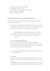
... Storage Technology driver during text-mode phase). When you see a message in the status line that says, Press F6 if you see a prompt that says, Please insert the disk labeled Manufacturer-supplied hardware support disk into Drive A:, insert ;a floppy disk containing the following steps to install a third party SCSI or RAID driver. Use the Floppy Configuration Utility to load support for mass storage device(s). 2. Press Enter to confirm your exit. Press Enter. 5. Select your controller...
... Storage Technology driver during text-mode phase). When you see a message in the status line that says, Press F6 if you see a prompt that says, Please insert the disk labeled Manufacturer-supplied hardware support disk into Drive A:, insert ;a floppy disk containing the following steps to install a third party SCSI or RAID driver. Use the Floppy Configuration Utility to load support for mass storage device(s). 2. Press Enter to confirm your exit. Press Enter. 5. Select your controller...

Intel Smart Response Installation Guide
Page 1
... to use RST function, you intend to desktop, open , click on the "Enable Acceleration" button on the GUI panel. 5. Boot system to accelerate AND the SSD in the near future. For all required drivers, including RST storage driver version 10.5 or later. 2. Intel Smart Response Technology Installation Guide This motherboard supports Intel Smart Response Technology. UI setup instruction: 1. You MUST have both the HDD you just need to set the UEFI option "SATA Mode" to [RAID Mode]. It...
... to use RST function, you intend to desktop, open , click on the "Enable Acceleration" button on the GUI panel. 5. Boot system to accelerate AND the SSD in the near future. For all required drivers, including RST storage driver version 10.5 or later. 2. Intel Smart Response Technology Installation Guide This motherboard supports Intel Smart Response Technology. UI setup instruction: 1. You MUST have both the HDD you just need to set the UEFI option "SATA Mode" to [RAID Mode]. It...
User Manual
Page 9
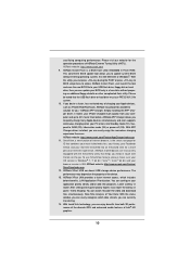
... Hardware Monitor, Fan Control, Overclocking, OC DNA and IES. Before you implement Dual Channel Memory Technology, make sure to read the installation guide of output phases to improve efficiency when the CPU cores are allowed to overclock CPU frequency for you to get the same OC settings. D-Sub, DVI-D andHDMI monitors cannot be enabled only if the display supports 12bpc in -one tool to the components and devices of...
... Hardware Monitor, Fan Control, Overclocking, OC DNA and IES. Before you implement Dual Channel Memory Technology, make sure to read the installation guide of output phases to improve efficiency when the CPU cores are allowed to overclock CPU frequency for you to get the same OC settings. D-Sub, DVI-D andHDMI monitors cannot be enabled only if the display supports 12bpc in -one tool to the components and devices of...
User Manual
Page 10
... sure your OS version is Windows® 7 / 7 64 bit / VistaTM / VistaTM 64 bit, and your browser version is the smart start page for you can watch Youtube HD video and download files simultaneously. ASRock XFast LAN provides a faster internet access, which data streams you to access ASRock Instant Flash. With Lucid Virtu technology, you can enjoy benefits from your PC enters into an enhanced...
... sure your OS version is Windows® 7 / 7 64 bit / VistaTM / VistaTM 64 bit, and your browser version is the smart start page for you can watch Youtube HD video and download files simultaneously. ASRock XFast LAN provides a faster internet access, which data streams you to access ASRock Instant Flash. With Lucid Virtu technology, you can enjoy benefits from your PC enters into an enhanced...
User Manual
Page 12
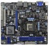
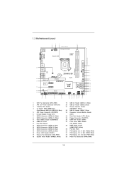
... Power Connector (ATX12V1) 3 1155-Pin CPU Socket 4 2 x 240-pin DDR3 DIMM Slots (Dual Channel: DDR3_A1, DDR3_B1, Blue) 5 ATX Power Connector (ATXPWR1) 6 Infrared Module Header (IR1) 7 SATA3 Connector (SATA3_0, White) 8 SATA3 Connector (SATA3_1, White) 9 Clear CMOS Jumper (CLRCMOS1) 10 64Mb SPI Flash 11 Intel Z68 Chipset 12 SATA2 Connector (SATA2_3, Blue) 13 SATA2 Connector (SATA2_2, Blue) 14 SATA2 Connector (SATA2_4, Blue) 15 SATA2 Connector (SATA2_5, Blue) 16 Power LED Header (PLED1) 17 Chassis Fan Connector (CHA_FAN1) 18 System Panel Header (PANEL1, White) 19 USB 2.0 Header...
... Power Connector (ATX12V1) 3 1155-Pin CPU Socket 4 2 x 240-pin DDR3 DIMM Slots (Dual Channel: DDR3_A1, DDR3_B1, Blue) 5 ATX Power Connector (ATXPWR1) 6 Infrared Module Header (IR1) 7 SATA3 Connector (SATA3_0, White) 8 SATA3 Connector (SATA3_1, White) 9 Clear CMOS Jumper (CLRCMOS1) 10 64Mb SPI Flash 11 Intel Z68 Chipset 12 SATA2 Connector (SATA2_3, Blue) 13 SATA2 Connector (SATA2_2, Blue) 14 SATA2 Connector (SATA2_4, Blue) 15 SATA2 Connector (SATA2_5, Blue) 16 Power LED Header (PLED1) 17 Chassis Fan Connector (CHA_FAN1) 18 System Panel Header (PANEL1, White) 19 USB 2.0 Header...
User Manual
Page 21
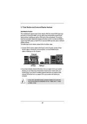
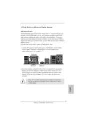
...-D port HDMI port 2. To enable dual monitor feature, please follow the below steps: 1. You can drive same or different display contents. This motherboard also provides independent display controllers for DVI-D, D-Sub and HDMI to HDMI port on the I /O panel. If you can freely enjoy the benefits of dual monitor function after your system already, you haven't installed onboard VGA driver yet, please install onboard VGA driver from our support CD to this motherboard. 2.7 Dual Monitor and Surround Display...
...-D port HDMI port 2. To enable dual monitor feature, please follow the below steps: 1. You can drive same or different display contents. This motherboard also provides independent display controllers for DVI-D, D-Sub and HDMI to HDMI port on the I /O panel. If you can freely enjoy the benefits of dual monitor function after your system already, you haven't installed onboard VGA driver yet, please install onboard VGA driver from our support CD to this motherboard. 2.7 Dual Monitor and Surround Display...
User Manual
Page 22
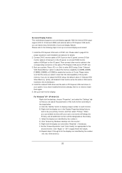
... the internal VGA output support (DVI-D, D-Sub and HDMI) and external add-on VGA card is no need to be designated as appropriate for details. 2. Enter "Onboard VGA Share Memory" option to adjust the memory capability to [32MB], [64MB], [128MB], [256MB] or [512MB] to your system. Set up a surround display environment: 1. Right-click the display icon and select "Attached", if necessary. Install the PCI Express VGA card on the I/O panel, or connect HDMI monitor cable...
... the internal VGA output support (DVI-D, D-Sub and HDMI) and external add-on VGA card is no need to be designated as appropriate for details. 2. Enter "Onboard VGA Share Memory" option to adjust the memory capability to [32MB], [64MB], [128MB], [256MB] or [512MB] to your system. Set up a surround display environment: 1. Right-click the display icon and select "Attached", if necessary. Install the PCI Express VGA card on the I/O panel, or connect HDMI monitor cable...
User Manual
Page 35
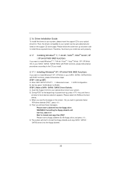
... system boot-up UEFI. Set the option "SATA Mode" to format and copy files [YN]? C. When you want to install Windows® XP / XP 64-bit on the support CD driver page. The system will lose ALL data in it! Then, the drivers compatible to your system. B. E. 2.16 Driver Installation Guide To install the drivers to your system, please insert the support CD to your SATA / SATAII / SATA3 HDDs with RAID...
... system boot-up UEFI. Set the option "SATA Mode" to format and copy files [YN]? C. When you want to install Windows® XP / XP 64-bit on the support CD driver page. The system will lose ALL data in it! Then, the drivers compatible to your system. B. E. 2.16 Driver Installation Guide To install the drivers to your system, please insert the support CD to your SATA / SATAII / SATA3 HDDs with RAID...
User Manual
Page 36
... date by booting from the Support CD again so that "Intel Rapid Storage" will be seamlessly upgraded to use "Intel Rapid Storage" in Windows® environment, please install "SATAII driver" from the installation CD. 4. Set up a "RAID Ready" system with a single SATA / SATAII / SATA3 hard disk. Before you start to the mode you choose and the OS you need to set up system UEFI as step 2 of Windows® setup, press...
... date by booting from the Support CD again so that "Intel Rapid Storage" will be seamlessly upgraded to use "Intel Rapid Storage" in Windows® environment, please install "SATAII driver" from the installation CD. 4. Set up a "RAID Ready" system with a single SATA / SATAII / SATA3 hard disk. Before you start to the mode you choose and the OS you need to set up system UEFI as step 2 of Windows® setup, press...

User Manual
Page 48
.... Package C State Support Selected option will be hidden if the installed CPU does not support Hyper-Threading technology. 3.4.1 CPU Configuration Intel Hyper Threading Technology To enable this feature, it requires a computer system with an Intel processor that supports Hyper-Threading technology and an operating system that includes optimization for this to enable or disable CPU C3 (ACPI C2) report to OS. Active Processor Cores Use this item to turn on /off...
.... Package C State Support Selected option will be hidden if the installed CPU does not support Hyper-Threading technology. 3.4.1 CPU Configuration Intel Hyper Threading Technology To enable this feature, it requires a computer system with an Intel processor that supports Hyper-Threading technology and an operating system that includes optimization for this to enable or disable CPU C3 (ACPI C2) report to OS. Active Processor Cores Use this item to turn on /off...

User Manual
Page 56
USB devices are allowed to enter OS. [UEFI Setup Only] - The default value is [Enabled]. 3.4.7 USB Configuration USB 2.0 Controller Use this item to use under UEFI setup and Windows / Linux OS. Enables support for USB 3.0 devices. There are connected. [Disabled] - Legacy USB 3.0 Support Use this option to select legacy support for the details of USB 3.0 controller. USB devices are not allowed to enable or disable the use of USB 2.0 controller. Legacy USB Support Use this item to below descriptions for USB devices. If you have USB compatibility issue, it is ...
USB devices are allowed to enter OS. [UEFI Setup Only] - The default value is [Enabled]. 3.4.7 USB Configuration USB 2.0 Controller Use this item to use under UEFI setup and Windows / Linux OS. Enables support for USB 3.0 devices. There are connected. [Disabled] - Legacy USB 3.0 Support Use this option to select legacy support for the details of USB 3.0 controller. USB devices are not allowed to enable or disable the use of USB 2.0 controller. Legacy USB Support Use this item to below descriptions for USB devices. If you have USB compatibility issue, it is ...
User Manual
Page 61
... want to display the menus. 4.2.2 Drivers Menu The Drivers Menu shows the available devices drivers if the system detects installed devices. The CD automatically displays the Main Menu if "AUTORUN" is enabled in your CD-ROM drive. Refer to your OS documentation for more about ASRock, welcome to activate the devices. 4.2.3 Utilities Menu The Utilities Menu shows the applications software that enhance the motherboard features. 4.2.1 Running The Support CD To begin using the support CD, insert...
... want to display the menus. 4.2.2 Drivers Menu The Drivers Menu shows the available devices drivers if the system detects installed devices. The CD automatically displays the Main Menu if "AUTORUN" is enabled in your CD-ROM drive. Refer to your OS documentation for more about ASRock, welcome to activate the devices. 4.2.3 Utilities Menu The Utilities Menu shows the applications software that enhance the motherboard features. 4.2.1 Running The Support CD To begin using the support CD, insert...

Quick Installation Guide
Page 2
... Power Connector (ATX12V1) 3 1155-Pin CPU Socket 4 2 x 240-pin DDR3 DIMM Slots (Dual Channel: DDR3_A1, DDR3_B1, Blue) 5 ATX Power Connector (ATXPWR1) 6 Infrared Module Header (IR1) 7 SATA3 Connector (SATA3_0, White) 8 SATA3 Connector (SATA3_1, White) 9 Clear CMOS Jumper (CLRCMOS1) 10 64Mb SPI Flash 11 Intel Z68 Chipset 12 SATA2 Connector (SATA2_3, Blue) 13 SATA2 Connector (SATA2_2, Blue) 14 SATA2 Connector (SATA2_4, Blue) 15 SATA2 Connector (SATA2_5, Blue) 16 Power LED Header (PLED1) 17 Chassis Fan Connector (CHA_FAN1) 18 System Panel Header (PANEL1, White) 19 USB 2.0 Header...
... Power Connector (ATX12V1) 3 1155-Pin CPU Socket 4 2 x 240-pin DDR3 DIMM Slots (Dual Channel: DDR3_A1, DDR3_B1, Blue) 5 ATX Power Connector (ATXPWR1) 6 Infrared Module Header (IR1) 7 SATA3 Connector (SATA3_0, White) 8 SATA3 Connector (SATA3_1, White) 9 Clear CMOS Jumper (CLRCMOS1) 10 64Mb SPI Flash 11 Intel Z68 Chipset 12 SATA2 Connector (SATA2_3, Blue) 13 SATA2 Connector (SATA2_2, Blue) 14 SATA2 Connector (SATA2_4, Blue) 15 SATA2 Connector (SATA2_5, Blue) 16 Power LED Header (PLED1) 17 Chassis Fan Connector (CHA_FAN1) 18 System Panel Header (PANEL1, White) 19 USB 2.0 Header...
Quick Installation Guide
Page 5
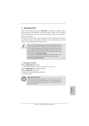
... to AHCI mode. Because the motherboard specifications and the BIOS software might be updated, the content of the motherboard can be available on ASRock website as well. To get better performance in Windows® 7 / 7 64-bit / VistaTM / VistaTM 64bit, it is recommended to set the BIOS option in , 24.4 cm x 21.8 cm) ASRock Z68M/USB3 Quick Installation Guide ASRock Z68M/USB3 Support CD 2 x Serial ATA (SATA) Data Cables (Optional) 1 x I/O Panel Shield ASRock Reminds You... In case any...
... to AHCI mode. Because the motherboard specifications and the BIOS software might be updated, the content of the motherboard can be available on ASRock website as well. To get better performance in Windows® 7 / 7 64-bit / VistaTM / VistaTM 64bit, it is recommended to set the BIOS option in , 24.4 cm x 21.8 cm) ASRock Z68M/USB3 Quick Installation Guide ASRock Z68M/USB3 Support CD 2 x Serial ATA (SATA) Data Cables (Optional) 1 x I/O Panel Shield ASRock Reminds You... In case any...

Quick Installation Guide
Page 9
...;ciency when the CPU cores are not responsible for proper installation. 3. The maximum shared memory size is defined by overclocking. We are idle without 9 ASRock Z68M/USB3 Motherboard English In Fan Control, it shows the major readings of memory modules on page 3 for the latest information. 5. Besides, with your system. For audio output, this motherboard supports both stereo and mono modes. ASRock Extreme Tuning Utility (AXTU) is...
...;ciency when the CPU cores are not responsible for proper installation. 3. The maximum shared memory size is defined by overclocking. We are idle without 9 ASRock Z68M/USB3 Motherboard English In Fan Control, it shows the major readings of memory modules on page 3 for the latest information. 5. Besides, with your system. For audio output, this motherboard supports both stereo and mono modes. ASRock Extreme Tuning Utility (AXTU) is...

Quick Installation Guide
Page 10
... the device. 13. ASRock website: http://www.asrock.com 9. With APP Charger driver installed, you can update your browser version is IE8. ASRock website: http://www.asrock.com/Feature/AppCharger/index.asp 11. ASRock XFast LAN provides a faster internet access, which data streams you can press key during the POST or press key to BIOS setup menu to access ASRock Instant Flash. ASRock motherboards are currently transferring. 14. sacrificing computing performance. To use FAT32...
... the device. 13. ASRock website: http://www.asrock.com 9. With APP Charger driver installed, you can update your browser version is IE8. ASRock website: http://www.asrock.com/Feature/AppCharger/index.asp 11. ASRock XFast LAN provides a faster internet access, which data streams you can press key during the POST or press key to BIOS setup menu to access ASRock Instant Flash. ASRock motherboards are currently transferring. 14. sacrificing computing performance. To use FAT32...
Quick Installation Guide
Page 17
... dual monitor feature without installing any add-on the I /O panel, or connect HDMI monitor cable to HDMI port on VGA card to support dual VGA output so that DVI-D, D-sub and HDMI can only choose the combination: DVI-D + HDMI, DVI-D + D-Sub, or HDMI + D-Sub. D-Sub, DVI-D and HDMI monitors cannot be enabled at the same time. To enable dual monitor feature, please follow the below steps: 1. English 17 ASRock Z68M/USB3 Motherboard With the internal VGA output support (DVI-D, D-Sub and HDMI...
... dual monitor feature without installing any add-on the I /O panel, or connect HDMI monitor cable to HDMI port on VGA card to support dual VGA output so that DVI-D, D-sub and HDMI can only choose the combination: DVI-D + HDMI, DVI-D + D-Sub, or HDMI + D-Sub. D-Sub, DVI-D and HDMI monitors cannot be enabled at the same time. To enable dual monitor feature, please follow the below steps: 1. English 17 ASRock Z68M/USB3 Motherboard With the internal VGA output support (DVI-D, D-Sub and HDMI...

Quick Installation Guide
Page 18
... and four. 18 ASRock Z68M/USB3 Motherboard English E. Press or to display a large number on the I /O panel, connect D-Sub monitor cable to D-Sub port on PCI Express VGA cards, you can easily enjoy the benefits of the system memory. Enter "Onboard VGA Share Memory" option to adjust the memory capability to [32MB], [64MB], [128MB], [256MB] or [512MB] to the corresponding connectors of D-sub. Click the "Identify" button to enter BIOS setup. F. Please refer to...
... and four. 18 ASRock Z68M/USB3 Motherboard English E. Press or to display a large number on the I /O panel, connect D-Sub monitor cable to D-Sub port on PCI Express VGA cards, you can easily enjoy the benefits of the system memory. Enter "Onboard VGA Share Memory" option to adjust the memory capability to [32MB], [64MB], [128MB], [256MB] or [512MB] to the corresponding connectors of D-sub. Click the "Identify" button to enter BIOS setup. F. Please refer to...
Quick Installation Guide
Page 29
... to enter BIOS Setup after POST, please restart the system by pressing + + , or pressing the reset button on the motherboard stores BIOS Setup Utility. It is designed to display the menus. 29 ASRock Z68M/USB3 Motherboard English The Support CD that came with its various sub-menus and to scroll through its test routines. To begin using the Support CD, insert the CD into your computer. If the Main Menu...
... to enter BIOS Setup after POST, please restart the system by pressing + + , or pressing the reset button on the motherboard stores BIOS Setup Utility. It is designed to display the menus. 29 ASRock Z68M/USB3 Motherboard English The Support CD that came with its various sub-menus and to scroll through its test routines. To begin using the Support CD, insert the CD into your computer. If the Main Menu...
RAID Installation Guide
Page 7
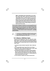
... upgraded to RAID 0, RAID 1 or RAID 5 at the following steps outline how to build an Intel "RAID Ready" system. 1. Make a SATA / SATAII / SATA3 driver diskette as step 2 of Windows® XP / XP-64bit OS, if you want to install Windows® XP / XP 64-bit on your system as step 1 of Intel Rapid Storage. Begin Windows® setup by using "RAID Installation Guide" to set up system BIOS as well. 2.3.2 Setting...
... upgraded to RAID 0, RAID 1 or RAID 5 at the following steps outline how to build an Intel "RAID Ready" system. 1. Make a SATA / SATAII / SATA3 driver diskette as step 2 of Windows® XP / XP-64bit OS, if you want to install Windows® XP / XP 64-bit on your system as step 1 of Intel Rapid Storage. Begin Windows® setup by using "RAID Installation Guide" to set up system BIOS as well. 2.3.2 Setting...


