
User Manual
Page 5
...Package Contents 1 1.2 Specifications 2 1.3 Motherboard Layout 7 1.4 I/O Panel 10 1.5 WiFi-802.11ac Module and ASRock WiFi 2.4/5 GHz Antennas (for Z370 Killer SLI/ac only) 13 Chapter 2 Installation 15 2.1 Installing the CPU 16 2.2 Installing the CPU Fan and Heatsink 19 2.3 Installing Memory Modules (DIMM) 20 2.4 Expansion Slots (PCI Express Slots) 22 2.5 Jumpers Setup 23 2.6 Onboard Headers and Connectors 24 2.7 SLITM and Quad SLITM Operation Guide 29 2.7.1 Installing Two SLITM-Ready Graphics Cards 29 2.7.2 Driver Installation and Setup 31 2.8 CrossFireXTM and...
...Package Contents 1 1.2 Specifications 2 1.3 Motherboard Layout 7 1.4 I/O Panel 10 1.5 WiFi-802.11ac Module and ASRock WiFi 2.4/5 GHz Antennas (for Z370 Killer SLI/ac only) 13 Chapter 2 Installation 15 2.1 Installing the CPU 16 2.2 Installing the CPU Fan and Heatsink 19 2.3 Installing Memory Modules (DIMM) 20 2.4 Expansion Slots (PCI Express Slots) 22 2.5 Jumpers Setup 23 2.6 Onboard Headers and Connectors 24 2.7 SLITM and Quad SLITM Operation Guide 29 2.7.1 Installing Two SLITM-Ready Graphics Cards 29 2.7.2 Driver Installation and Setup 31 2.8 CrossFireXTM and...
User Manual
Page 8
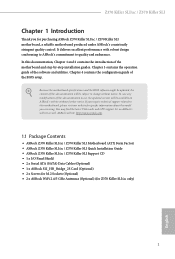
... (Optional) (for specific information about the model you for purchasing ASRock Z370 Killer SLI/ac / Z370 Killer SLI motherboard, a reliable motherboard produced under ASRock's consistently stringent quality control. Chapter 4 contains the configuration guide of the motherboard and step-by-step installation guides. Because the motherboard specifications and the BIOS software might be updated, the content of this documentation occur, the updated version will be available on ASRock's website as well. You may find the latest VGA cards and CPU support list on ASRock...
... (Optional) (for specific information about the model you for purchasing ASRock Z370 Killer SLI/ac / Z370 Killer SLI motherboard, a reliable motherboard produced under ASRock's consistently stringent quality control. Chapter 4 contains the configuration guide of the motherboard and step-by-step installation guides. Because the motherboard specifications and the BIOS software might be updated, the content of this documentation occur, the updated version will be available on ASRock's website as well. You may find the latest VGA cards and CPU support list on ASRock...

User Manual
Page 9
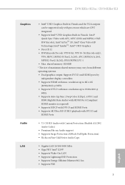
...))* * Supports NVMe SSD as boot disks • 4 x PCI Express 3.0 x1 Slots (Flexible PCIe) • Supports AMD Quad CrossFireXTM and CrossFireXTM • Supports NVIDIA® Quad SLITM and SLITM • 1 x Vertical M.2 Socket (Key E) with the bundled WiFi- 802.11ac module (on ASRock's website for Z370 Killer SLI/ac only) • 15μ Gold Contact in nonECC mode) • Max. 1.2 Specifications Platform • ATX Form Factor CPU • Supports 8th Generation Intel® CoreTM Processors (Socket...
...))* * Supports NVMe SSD as boot disks • 4 x PCI Express 3.0 x1 Slots (Flexible PCIe) • Supports AMD Quad CrossFireXTM and CrossFireXTM • Supports NVIDIA® Quad SLITM and SLITM • 1 x Vertical M.2 Socket (Key E) with the bundled WiFi- 802.11ac module (on ASRock's website for Z370 Killer SLI/ac only) • 15μ Gold Contact in nonECC mode) • Max. 1.2 Specifications Platform • ATX Form Factor CPU • Supports 8th Generation Intel® CoreTM Processors (Socket...
User Manual
Page 10
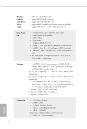
... memory 1024MB * The size of maximum shared memory may vary from different operating systems. • Dual graphics output: Support DVI-D and HDMI ports by independent display controllers • Supports HDMI with AVC, MVC (S3D) and MPEG-2 Full HW Encode1, Intel® InTruTM 3D, Intel® Clear Video HD Technology, Intel® InsiderTM, Intel® UHD Graphics • DirectX 12 • HWAEncode/Decode: VP9 8-bit, VP9 10- Z370 Killer SLI/ac / Z370 Killer SLI Graphics Audio LAN...
... memory 1024MB * The size of maximum shared memory may vary from different operating systems. • Dual graphics output: Support DVI-D and HDMI ports by independent display controllers • Supports HDMI with AVC, MVC (S3D) and MPEG-2 Full HW Encode1, Intel® InTruTM 3D, Intel® Clear Video HD Technology, Intel® InsiderTM, Intel® UHD Graphics • DirectX 12 • HWAEncode/Decode: VP9 8-bit, VP9 10- Z370 Killer SLI/ac / Z370 Killer SLI Graphics Audio LAN...
User Manual
Page 11
...Antenna Ports (for Z370 Killer SLI/ac only) • 1 x PS/2 Mouse/Keyboard Port • 1 x DVI-D Port • 1 x HDMI Port • 1 x Optical SPDIF Out Port • 5 x USB 3.1 Gen1 Type-A Ports (Supports ESD Protection) • 1 x USB 3.1 Gen1 Type-C Port (Supports ESD Protection) • 1 x RJ-45 LAN Port with LED (ACT/LINK LED and SPEED LED) • HD Audio Jacks: Rear Speaker / Central / Bass / Line in / Front Speaker / Microphone Storage • 6 x SATA3 6.0 Gb/s Connectors, support RAID (RAID 0, RAID 1, RAID 5, RAID 10, Intel Rapid Storage Technology 15), NCQ, AHCI and Hot Plug...
...Antenna Ports (for Z370 Killer SLI/ac only) • 1 x PS/2 Mouse/Keyboard Port • 1 x DVI-D Port • 1 x HDMI Port • 1 x Optical SPDIF Out Port • 5 x USB 3.1 Gen1 Type-A Ports (Supports ESD Protection) • 1 x USB 3.1 Gen1 Type-C Port (Supports ESD Protection) • 1 x RJ-45 LAN Port with LED (ACT/LINK LED and SPEED LED) • HD Audio Jacks: Rear Speaker / Central / Bass / Line in / Front Speaker / Microphone Storage • 6 x SATA3 6.0 Gb/s Connectors, support RAID (RAID 0, RAID 1, RAID 5, RAID 10, Intel Rapid Storage Technology 15), NCQ, AHCI and Hot Plug...

User Manual
Page 12
...8226; 1 x 8 pin 12V Power Connector • 1 x Front Panel Audio Connector • 1 x Thunderbolt AIC Connector (5-pin) • 2 x USB 2.0 Headers (Support 4 USB 2.0 ports) (Supports ESD Protection) • 1 x USB 3.1 Gen1 Header (Supports 2 USB 3.1 Gen1 ports) (Supports ESD Protection) • 1 x Front Panel Type C USB 3.1 Gen1 Header • 1 x Performance Mode / Easy OC Header BIOS Feature • AMI UEFI Legal BIOS with multilingual GUI support • ACPI 6.0 Compliant wake up events • SMBIOS 2.7 Support • CPU Vcore, DRAM, PCH 1.0V, VCCIO, VCCST, VCCSA Voltage Multi...
...8226; 1 x 8 pin 12V Power Connector • 1 x Front Panel Audio Connector • 1 x Thunderbolt AIC Connector (5-pin) • 2 x USB 2.0 Headers (Support 4 USB 2.0 ports) (Supports ESD Protection) • 1 x USB 3.1 Gen1 Header (Supports 2 USB 3.1 Gen1 ports) (Supports ESD Protection) • 1 x Front Panel Type C USB 3.1 Gen1 Header • 1 x Performance Mode / Easy OC Header BIOS Feature • AMI UEFI Legal BIOS with multilingual GUI support • ACPI 6.0 Compliant wake up events • SMBIOS 2.7 Support • CPU Vcore, DRAM, PCH 1.0V, VCCIO, VCCST, VCCSA Voltage Multi...

User Manual
Page 14
1.3 Motherboard Layout Z370 Killer SLI/ac Z370 Killer SLI/ac / Z370 Killer SLI PS2 Keyboard /Mouse USB 3.1 Gen1 T: USB1 B: USB2 HDMI1 M2_WIFI1 ATX12V1 CPU_FAN1 DDR4_A1 (64 bit, 288-pin module) DDR4_A2 (64 bit, 288-pin module) DDR4_B1 (64 bit, 288-pin module) DDR4_B2 (64 bit, 288-pin module) ATXPWR1 DVI1 USB 3.1 Gen1 T: USB3_TA_1 B: USB3_TC_1 USB 3.1 Gen1 T: USB3 B: USB4 Top: RJ-45 Top: Central/Bass LINE IN Center: REAR SPK Bottom: Optical SPDIF Top: Center: FRONT...
1.3 Motherboard Layout Z370 Killer SLI/ac Z370 Killer SLI/ac / Z370 Killer SLI PS2 Keyboard /Mouse USB 3.1 Gen1 T: USB1 B: USB2 HDMI1 M2_WIFI1 ATX12V1 CPU_FAN1 DDR4_A1 (64 bit, 288-pin module) DDR4_A2 (64 bit, 288-pin module) DDR4_B1 (64 bit, 288-pin module) DDR4_B2 (64 bit, 288-pin module) ATXPWR1 DVI1 USB 3.1 Gen1 T: USB3_TA_1 B: USB3_TC_1 USB 3.1 Gen1 T: USB3 B: USB4 Top: RJ-45 Top: Central/Bass LINE IN Center: REAR SPK Bottom: Optical SPDIF Top: Center: FRONT...

User Manual
Page 16
... SATA3 Connectors (SATA_0_1) 11 System Panel Header (PANEL1) 12 Power LED and Speaker Header (SPK_PLED1) 13 Chassis Fan / Waterpump Fan Connector (CHA_FAN3/W_PUMP) 14 Chassis Fan Connector (CHA_FAN1) 15 USB 2.0 Header (USB_1_2) 16 USB 2.0 Header (USB_3_4) 17 Performance Mode / Easy OC Header (PM_EO) 18 Chassis Intrusion Header (CI1) 19 RGB LED Header (RGB_LED) 20 Clear CMOS Jumper (CLRMOS1) 21 Thunderbolt AIC Connector (TB2) 22 TPM Header (TPMS1) 23 COM Port Header (COM1) 24 Front Panel Audio Header (HD_AUDIO1) 25 Chassis Fan Connector (CHA_FAN2) 9 English Z370 Killer SLI/ac / Z370 Killer SLI...
... SATA3 Connectors (SATA_0_1) 11 System Panel Header (PANEL1) 12 Power LED and Speaker Header (SPK_PLED1) 13 Chassis Fan / Waterpump Fan Connector (CHA_FAN3/W_PUMP) 14 Chassis Fan Connector (CHA_FAN1) 15 USB 2.0 Header (USB_1_2) 16 USB 2.0 Header (USB_3_4) 17 Performance Mode / Easy OC Header (PM_EO) 18 Chassis Intrusion Header (CI1) 19 RGB LED Header (RGB_LED) 20 Clear CMOS Jumper (CLRMOS1) 21 Thunderbolt AIC Connector (TB2) 22 TPM Header (TPMS1) 23 COM Port Header (COM1) 24 Front Panel Audio Header (HD_AUDIO1) 25 Chassis Fan Connector (CHA_FAN2) 9 English Z370 Killer SLI/ac / Z370 Killer SLI...

User Manual
Page 30
..., use a jumper cap to clear the data in CMOS. After waiting for 5 seconds. Clear CMOS Jumper (CLRMOS1) (see p.7 or 8, No. 20) Default Clear CMOS CLRMOS1 allows you to short pin2 and pin3 on the pins, the jumper is removed. Please be noted that the password, date, time, and user default profile will be cleared only if the CMOS battery is "Open". If you update the BIOS. Z370 Killer SLI/ac / Z370 Killer SLI 2.5 Jumpers Setup The illustration shows how jumpers are "Short...
..., use a jumper cap to clear the data in CMOS. After waiting for 5 seconds. Clear CMOS Jumper (CLRMOS1) (see p.7 or 8, No. 20) Default Clear CMOS CLRMOS1 allows you to short pin2 and pin3 on the pins, the jumper is removed. Please be noted that the password, date, time, and user default profile will be cleared only if the CMOS battery is "Open". If you update the BIOS. Z370 Killer SLI/ac / Z370 Killer SLI 2.5 Jumpers Setup The illustration shows how jumpers are "Short...

User Manual
Page 34
... PCIE4 (default slot). English 27 If you plan to connect a 3-Pin CPU fan, please connect it along Pin 1 and Pin 5. Please connect a Thunderbolt™ add-in card (AIC) to the Thunderbolt AIC connector via the GPIO cable. * Please install the Thunderbolt™ AIC card to Pin 1-3. 12 24 1 13 This motherboard provides a 24-pin ATX power connector. RRXD1 DDTR#1 DDSR#1 CCTS#1 1 RRI#1 RRTS#1 GND TTXD1 DDCD#1 This COM1 header supports a serial port module. Z370 Killer SLI/ac / Z370 Killer SLI CPU Fan Connector (4-pin CPU_FAN1...
... PCIE4 (default slot). English 27 If you plan to connect a 3-Pin CPU fan, please connect it along Pin 1 and Pin 5. Please connect a Thunderbolt™ add-in card (AIC) to the Thunderbolt AIC connector via the GPIO cable. * Please install the Thunderbolt™ AIC card to Pin 1-3. 12 24 1 13 This motherboard provides a 24-pin ATX power connector. RRXD1 DDTR#1 DDSR#1 CCTS#1 1 RRI#1 RRTS#1 GND TTXD1 DDCD#1 This COM1 header supports a serial port module. Z370 Killer SLI/ac / Z370 Killer SLI CPU Fan Connector (4-pin CPU_FAN1...

User Manual
Page 36
... other graphics card to the PCI Express graphics cards. 29 English Step 2 If required, connect the auxiliary power source to PCIE4 slot. Z370 Killer SLI/ac / Z370 Killer SLI 2.7 SLITM and Quad SLITM Operation Guide This motherboard supports NVIDIA® SLITM and Quad SLITM (Scalable Link Interface) technology that allows you to install up to use identical SLITM-ready graphics cards that your power supply unit (PSU) can provide at least the minimum power your graphics card driver supports NVIDIA...
... other graphics card to the PCI Express graphics cards. 29 English Step 2 If required, connect the auxiliary power source to PCIE4 slot. Z370 Killer SLI/ac / Z370 Killer SLI 2.7 SLITM and Quad SLITM Operation Guide This motherboard supports NVIDIA® SLITM and Quad SLITM (Scalable Link Interface) technology that allows you to install up to use identical SLITM-ready graphics cards that your power supply unit (PSU) can provide at least the minimum power your graphics card driver supports NVIDIA...

User Manual
Page 39
... the AMD's website for detailed installation guide. 2.8.1 Installing Two CrossFireXTM-Ready Graphics Cards Step 1 Insert one graphics card into PCIE2 slot and the other graphics card to AMD graphics card manuals for details. 4. You should only use a AMD certified PSU. Please refer to PCIE4 slot. Make sure that the cards are AMD certified. 2. Please refer to enable CrossFireXTM. Download the drivers from the AMD's website: www.amd.com 3. 2.8 CrossFireXTM and Quad CrossFireXTM Operation Guide This motherboard supports CrossFireXTM...
... the AMD's website for detailed installation guide. 2.8.1 Installing Two CrossFireXTM-Ready Graphics Cards Step 1 Insert one graphics card into PCIE2 slot and the other graphics card to AMD graphics card manuals for details. 4. You should only use a AMD certified PSU. Please refer to PCIE4 slot. Make sure that the cards are AMD certified. 2. Please refer to enable CrossFireXTM. Download the drivers from the AMD's website: www.amd.com 3. 2.8 CrossFireXTM and Quad CrossFireXTM Operation Guide This motherboard supports CrossFireXTM...

User Manual
Page 41
Please check AMD's website for AMD driver updates. We recommend using this utility to uninstall any VGA drivers installed in the Windows® system tray. Select the GPU number according to installation. 2.8.2 Driver Installation and Setup Step 1 Power on your graphics card and click Apply. Step 2 Remove the AMD drivers if you have any previously installed Catalyst drivers prior to your computer and boot into OS. Step 3 Install the required drivers and CATALYST Control Center then restart...
Please check AMD's website for AMD driver updates. We recommend using this utility to uninstall any VGA drivers installed in the Windows® system tray. Select the GPU number according to installation. 2.8.2 Driver Installation and Setup Step 1 Power on your graphics card and click Apply. Step 2 Remove the AMD drivers if you have any previously installed Catalyst drivers prior to your computer and boot into OS. Step 3 Install the required drivers and CATALYST Control Center then restart...

User Manual
Page 46
... menu. Z370 Killer SLI/ac / Z370 Killer SLI Chapter 3 Software and Utilities Operation 3.1 Installing Drivers The Support CD that comes with the motherboard contains necessary drivers and useful utilities that the motherboard supports. Running The Support CD To begin using the support CD, insert the CD into your computer. Drivers Menu The drivers compatible to install it. 39 English If the Main Menu does not appear automatically, locate and double click on the support CD driver page. Therefore, the drivers you install can work...
... menu. Z370 Killer SLI/ac / Z370 Killer SLI Chapter 3 Software and Utilities Operation 3.1 Installing Drivers The Support CD that comes with the motherboard contains necessary drivers and useful utilities that the motherboard supports. Running The Support CD To begin using the support CD, insert the CD into your computer. Drivers Menu The drivers compatible to install it. 39 English If the Main Menu does not appear automatically, locate and double click on the support CD driver page. Therefore, the drivers you install can work...

User Manual
Page 77
... link speed for PCIE1. 4.6.2 Chipset Configuration Primary Graphics Adapter Select a primary VGA. PCIE1 Link Speed Select the link speed for PCIE2. 70 English Above 4G Decoding Enable or disable 64bit capable Devices to be decoded in Above 4G Address Space (only if the system supports 64 bit PCI decoding). VT-d Intel® Virtualization Technology for Directed I/O helps your virtual machine monitor better utilize hardware by improving application compatibility and...
... link speed for PCIE1. 4.6.2 Chipset Configuration Primary Graphics Adapter Select a primary VGA. PCIE1 Link Speed Select the link speed for PCIE2. 70 English Above 4G Decoding Enable or disable 64bit capable Devices to be decoded in Above 4G Address Space (only if the system supports 64 bit PCI decoding). VT-d Intel® Virtualization Technology for Directed I/O helps your virtual machine monitor better utilize hardware by improving application compatibility and...

User Manual
Page 79
... controller. Onboard HD Audio Enable/disable onboard HD audio. Front Panel Enable/disable front panel HD audio. If [Power On] is selected, the system will remain off the LED in S5 Turn on AC/Power Loss Select the power state after a power failure. Turn On LED in the ACPI S5 state. 72 English Onboard HDMI HD Audio Enable audio for power saving when the computer is selected, the power will start to enable onboard HD audio and automatically disable it when a sound card is installed. Set to Auto to boot...
... controller. Onboard HD Audio Enable/disable onboard HD audio. Front Panel Enable/disable front panel HD audio. If [Power On] is selected, the system will remain off the LED in S5 Turn on AC/Power Loss Select the power state after a power failure. Turn On LED in the ACPI S5 state. 72 English Onboard HDMI HD Audio Enable audio for power saving when the computer is selected, the power will start to enable onboard HD audio and automatically disable it when a sound card is installed. Set to Auto to boot...

User Manual
Page 82
4.6.5 Super IO Configuration Z370 Killer SLI/ac / Z370 Killer SLI Serial Port Enable or disable the Serial port. Serial Port Address Select the address of the Serial port. PS2 Y-Cable Enable the PS2 Y-Cable or set this option to Auto. 75 English
4.6.5 Super IO Configuration Z370 Killer SLI/ac / Z370 Killer SLI Serial Port Enable or disable the Serial port. Serial Port Address Select the address of the Serial port. PS2 Y-Cable Enable the PS2 Y-Cable or set this option to Auto. 75 English

User Manual
Page 88
... (Auto IP), Auto ASRock Internet Flash downloads and updates the latest UEFI firmware version from our servers for the Boot Manager. Boot Manager Timeout Enable/disable the Boot Manager Timeout. Z370 Killer SLI/ac / Z370 Killer SLI Boot Manager Boot Manager is recommended to plug in your USB storage device and run Instant Flash to update your USB pen drive before using this tool. Instant Flash Save UEFI files in your UEFI. Please setup network configuration before using Internet Flash. *For BIOS backup and recovery purpose, it is specifically designed for the dual OS...
... (Auto IP), Auto ASRock Internet Flash downloads and updates the latest UEFI firmware version from our servers for the Boot Manager. Boot Manager Timeout Enable/disable the Boot Manager Timeout. Z370 Killer SLI/ac / Z370 Killer SLI Boot Manager Boot Manager is recommended to plug in your USB storage device and run Instant Flash to update your USB pen drive before using this tool. Instant Flash Save UEFI files in your UEFI. Please setup network configuration before using Internet Flash. *For BIOS backup and recovery purpose, it is specifically designed for the dual OS...

User Manual
Page 89
Internet Setting Enable or disable sound effects in the setup utility. UEFI Download Server Select a server to configure internet connection settings for Internet Flash. Network Configuration Use this to download the UEFI firmware. 82 English
Internet Setting Enable or disable sound effects in the setup utility. UEFI Download Server Select a server to configure internet connection settings for Internet Flash. Network Configuration Use this to download the UEFI firmware. 82 English

User Manual
Page 93
... Password Set or change the password for the administrator account. User Password Set or change the password for the user account. Disable this option to change the supervisor/user password for Secure Boot. Leave it blank and press enter to change the settings in the UEFI Setup Utility. Users are unable to remove the password. Secure Boot Use this item to remove the password. 4.9 Security Screen In this section you may also clear the user password. Leave it blank and press enter to enable or disable support...
... Password Set or change the password for the administrator account. User Password Set or change the password for the user account. Disable this option to change the supervisor/user password for Secure Boot. Leave it blank and press enter to change the settings in the UEFI Setup Utility. Users are unable to remove the password. Secure Boot Use this item to remove the password. 4.9 Security Screen In this section you may also clear the user password. Leave it blank and press enter to enable or disable support...


