
Intel Smart Response Installation Guide
Page 1
Intel Smart Response Technology Installation Guide This motherboard supports Intel Smart Response Technology. For the new version RST driver, please check our website for the latest information: http://www.asrock.com * Before you use RST function, you just need to set the UEFI option "SATA Mode" to show the newly accelerated system configuration. * Intel® will refresh to [RAID Mode]. UI setup instruction: 1. After clicking OK button, SRT will enable automatically, and the RST GUI...
Intel Smart Response Technology Installation Guide This motherboard supports Intel Smart Response Technology. For the new version RST driver, please check our website for the latest information: http://www.asrock.com * Before you use RST function, you just need to set the UEFI option "SATA Mode" to show the newly accelerated system configuration. * Intel® will refresh to [RAID Mode]. UI setup instruction: 1. After clicking OK button, SRT will enable automatically, and the RST GUI...
Intel Rapid Storage Guide
Page 13
...-supplied hardware support disk into Drive A:, insert ;a floppy disk containing the following steps to install a third party SCSI or RAID driver. Press Enter. 5. At this point, you need to install the Intel Rapid Storage Technology driver during text-mode phase). Select 4: Exit and press Enter. 11. Install the RAID Driver Using the F6 Installation Method Perform the following files: IAAHCI.INF, IAAHCI.CAT, IASTOR.INF, IASTOR.CAT, IASTOR.SYS, and TXTSETUP.OEM. Setup...
...-supplied hardware support disk into Drive A:, insert ;a floppy disk containing the following steps to install a third party SCSI or RAID driver. Press Enter. 5. At this point, you need to install the Intel Rapid Storage Technology driver during text-mode phase). Select 4: Exit and press Enter. 11. Install the RAID Driver Using the F6 Installation Method Perform the following files: IAAHCI.INF, IAAHCI.CAT, IASTOR.INF, IASTOR.CAT, IASTOR.SYS, and TXTSETUP.OEM. Setup...

Intel Rapid Storage Guide
Page 16
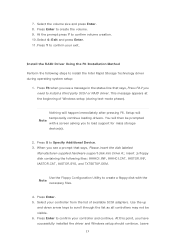
... load support for mass storage device(s). 2. How to load the driver during OS installation using the F6 installation method. 1. You can use the Floppy Configuration Utility to create a floppy disk with a screen asking you see a prompt that says, Please insert the disk labeled Manufacturer-supplied hardware support disk into Drive A:, insert a floppy disk containing the following steps to install the Intel® Rapid Storage Technology driver using F6 when in AHCI/RAID mode In order to install an operating system onto a single Serial...
... load support for mass storage device(s). 2. How to load the driver during OS installation using the F6 installation method. 1. You can use the Floppy Configuration Utility to create a floppy disk with a screen asking you see a prompt that says, Please insert the disk labeled Manufacturer-supplied hardware support disk into Drive A:, insert a floppy disk containing the following steps to install the Intel® Rapid Storage Technology driver using F6 when in AHCI/RAID mode In order to install an operating system onto a single Serial...

RAID Installation Guide
Page 7
... installing the hard disk drives, please set the necessary RAID items in your USB flash drive into a USB port B. STEP 2: Use ASRock Easy RAID Installer Easy RAID Installer can copy the RAID driver from a support CD to your USB storage device with RAID functions, please follow the procedures below. Follow the onscreen instruction to confirm the selection C. Please note that this document for all models A. Go to Advanced Storage Configuration and set RAID configuration. Plug in the BIOS before setting your RAID configuration. 2.3 Installing Windows® 10 64-bit...
... installing the hard disk drives, please set the necessary RAID items in your USB flash drive into a USB port B. STEP 2: Use ASRock Easy RAID Installer Easy RAID Installer can copy the RAID driver from a support CD to your USB storage device with RAID functions, please follow the procedures below. Follow the onscreen instruction to confirm the selection C. Please note that this document for all models A. Go to Advanced Storage Configuration and set RAID configuration. Plug in the BIOS before setting your RAID configuration. 2.3 Installing Windows® 10 64-bit...

User Manual
Page 4
... Package Contents 1 1.2 Specifications 2 1.3 Motherboard Layout 7 1.4 I/O Panel 9 1.5 WiFi-802.11ac Module and ASRock WiFi 2.4/5 GHz Antenna (for Z270 Killer SLI/ac only) 12 Chapter 2 Installation 14 2.1 Installing the CPU 15 2.2 Installing the CPU Fan and Heatsink 18 2.3 Installing Memory Modules (DIMM) 19 2.4 Expansion Slots (PCI Express Slots) 21 2.5 Jumpers Setup 22 2.6 Onboard Headers and Connectors 23 2.7 SLITM and Quad SLITM Operation Guide 28 2.7.1 Installing Two SLITM-Ready Graphics Cards 28 2.7.2 Driver Installation and Setup 30 2.8 CrossFireXTM and...
... Package Contents 1 1.2 Specifications 2 1.3 Motherboard Layout 7 1.4 I/O Panel 9 1.5 WiFi-802.11ac Module and ASRock WiFi 2.4/5 GHz Antenna (for Z270 Killer SLI/ac only) 12 Chapter 2 Installation 14 2.1 Installing the CPU 15 2.2 Installing the CPU Fan and Heatsink 18 2.3 Installing Memory Modules (DIMM) 19 2.4 Expansion Slots (PCI Express Slots) 21 2.5 Jumpers Setup 22 2.6 Onboard Headers and Connectors 23 2.7 SLITM and Quad SLITM Operation Guide 28 2.7.1 Installing Two SLITM-Ready Graphics Cards 28 2.7.2 Driver Installation and Setup 30 2.8 CrossFireXTM and...
User Manual
Page 7
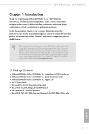
..., the updated version will be available on ASRock's website as well. Chapter 3 contains the operation guide of the BIOS setup. ASRock website http://www.asrock.com. 1.1 Package Contents • ASRock Z270 Killer SLI/ac / Z270 Killer SLI Motherboard (ATX Form Factor) • ASRock Z270 Killer SLI/ac / Z270 Killer SLI Quick Installation Guide • ASRock Z270 Killer SLI/ac / Z270 Killer SLI Support CD • 1 x I/O Panel Shield • 2 x Serial ATA (SATA) Data Cables (Optional) • 1 x ASRock SLI_HB_Bridge_2S Card (Optional) • 2 x Screws for M.2 Sockets (Optional...
..., the updated version will be available on ASRock's website as well. Chapter 3 contains the operation guide of the BIOS setup. ASRock website http://www.asrock.com. 1.1 Package Contents • ASRock Z270 Killer SLI/ac / Z270 Killer SLI Motherboard (ATX Form Factor) • ASRock Z270 Killer SLI/ac / Z270 Killer SLI Quick Installation Guide • ASRock Z270 Killer SLI/ac / Z270 Killer SLI Support CD • 1 x I/O Panel Shield • 2 x Serial ATA (SATA) Data Cables (Optional) • 1 x ASRock SLI_HB_Bridge_2S Card (Optional) • 2 x Screws for M.2 Sockets (Optional...
User Manual
Page 11
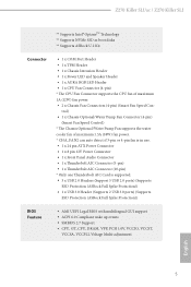
...Z270 Killer SLI/ac / Z270 Killer SLI ** Supports Intel® OptaneTM Technology ** Supports NVMe SSD as boot disks ** Supports ASRock U.2 Kit Connector • 1 x COM Port Header • 1 x TPM Header • 1 x Chassis Intrusion Header • 1 x Power LED and Speaker Header • 1 x AURA RGB LED Header • 1 x CPU Fan Connector (4-pin) * The CPU Fan Connector supports the CPU fan of maximum 1.5A (18W) fan power. * CHA_FAN2 can auto detect if 3-pin or 4-pin fan is in use. • 1 x 24 pin ATX Power Connector • 1 x 8 pin 12V Power Connector • 1 x Front Panel Audio...
...Z270 Killer SLI/ac / Z270 Killer SLI ** Supports Intel® OptaneTM Technology ** Supports NVMe SSD as boot disks ** Supports ASRock U.2 Kit Connector • 1 x COM Port Header • 1 x TPM Header • 1 x Chassis Intrusion Header • 1 x Power LED and Speaker Header • 1 x AURA RGB LED Header • 1 x CPU Fan Connector (4-pin) * The CPU Fan Connector supports the CPU fan of maximum 1.5A (18W) fan power. * CHA_FAN2 can auto detect if 3-pin or 4-pin fan is in use. • 1 x 24 pin ATX Power Connector • 1 x 8 pin 12V Power Connector • 1 x Front Panel Audio...

User Manual
Page 13
1.3 Motherboard Layout PS2 Keyboard /Mouse USB 3.0 T: USB1 B: USB2 HDMI1 M2_WIFI1* ATX12V1 Z270 Killer SLI/ac / Z270 Killer SLI CPU_FAN1 DDR4_A1 (64 bit, 288-pin module) DDR4_A2 (64 bit, 288-pin module) DDR4_B1 (64 bit, 288-pin module) DDR4_B2 (64 bit, 288-pin module) ATXPWR1 DVI1 USB 3.0 T: USB3_TA_1 B: USB3_TC_1 USB 3.0 T: USB3 B: USB4 Top: RJ-45 Top: Central/Bass LINE IN Center: REAR SPK Bottom: Optical SPDIF Top: Center: FRONT Bottom: MIC IN RoHS...
1.3 Motherboard Layout PS2 Keyboard /Mouse USB 3.0 T: USB1 B: USB2 HDMI1 M2_WIFI1* ATX12V1 Z270 Killer SLI/ac / Z270 Killer SLI CPU_FAN1 DDR4_A1 (64 bit, 288-pin module) DDR4_A2 (64 bit, 288-pin module) DDR4_B1 (64 bit, 288-pin module) DDR4_B2 (64 bit, 288-pin module) ATXPWR1 DVI1 USB 3.0 T: USB3_TA_1 B: USB3_TC_1 USB 3.0 T: USB3 B: USB4 Top: RJ-45 Top: Central/Bass LINE IN Center: REAR SPK Bottom: Optical SPDIF Top: Center: FRONT Bottom: MIC IN RoHS...

User Manual
Page 14
... System Panel Header (PANEL1) 11 Power LED and Speaker Header (SPK_PLED1) 12 Chassis Fan / Waterpump Fan Connector (CHA_FAN3/W_PUMP) 13 Chassis Fan Connector (CHA_FAN1) 14 USB 2.0 Header (USB_1_2) 15 USB 2.0 Header (USB_3_4) 16 Chassis Intrusion Header (CI1) 17 USB 2.0 Header (USB_5) 18 AURA RGB LED Header (RGB_LED) 19 Clear CMOS Jumper (CLRMOS1) 20 Thunderbolt AIC Connector (TB2) 21 TPM Header (TPMS1) 22 COM Port Header (COM1) 23 Front Panel Audio Header (HD_AUDIO1) 24 Thunderbolt AIC Connector (TB1) 25 Chassis Fan Connector (CHA_FAN2) * The Wireless LAN is supported on Z270 Killer SLI/ac...
... System Panel Header (PANEL1) 11 Power LED and Speaker Header (SPK_PLED1) 12 Chassis Fan / Waterpump Fan Connector (CHA_FAN3/W_PUMP) 13 Chassis Fan Connector (CHA_FAN1) 14 USB 2.0 Header (USB_1_2) 15 USB 2.0 Header (USB_3_4) 16 Chassis Intrusion Header (CI1) 17 USB 2.0 Header (USB_5) 18 AURA RGB LED Header (RGB_LED) 19 Clear CMOS Jumper (CLRMOS1) 20 Thunderbolt AIC Connector (TB2) 21 TPM Header (TPMS1) 22 COM Port Header (COM1) 23 Front Panel Audio Header (HD_AUDIO1) 24 Thunderbolt AIC Connector (TB1) 25 Chassis Fan Connector (CHA_FAN2) * The Wireless LAN is supported on Z270 Killer SLI/ac...

User Manual
Page 37
... Bridge is recommended to your graphics card driver supports AMD CrossFireXTM technology. It is provided with the graphics card you pair a 12-pipe CrossFireXTM Edition card with this motherboard. CrossFire Bridge Step 2 Connect two graphics cards by installing a CrossFire Bridge on the CrossFire Bridge Interconnects on the slots. You should only use a AMD certified PSU. Z270 Killer SLI/ac / Z270 Killer SLI 2.8 CrossFireXTM and Quad CrossFireXTM Operation Guide This motherboard supports CrossFireXTM and Quad CrossFireXTM that...
... Bridge is recommended to your graphics card driver supports AMD CrossFireXTM technology. It is provided with the graphics card you pair a 12-pipe CrossFireXTM Edition card with this motherboard. CrossFire Bridge Step 2 Connect two graphics cards by installing a CrossFire Bridge on the CrossFire Bridge Interconnects on the slots. You should only use a AMD certified PSU. Z270 Killer SLI/ac / Z270 Killer SLI 2.8 CrossFireXTM and Quad CrossFireXTM Operation Guide This motherboard supports CrossFireXTM and Quad CrossFireXTM that...
User Manual
Page 39
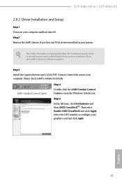
... using this utility to uninstall any VGA drivers installed in the Windows® system tray. Then select Enable AMD CrossFireX and click Apply. English 33 Please check AMD's website for AMD driver updates. Step 3 Install the required drivers and CATALYST Control Center then restart your graphics card and click Apply. AMD Catalyst Control Center Step 4 Double-click the AMD Catalyst Control Center icon in your computer and boot into OS. Z270 Killer SLI/ac / Z270 Killer SLI 2.8.2 Driver Installation and Setup...
... using this utility to uninstall any VGA drivers installed in the Windows® system tray. Then select Enable AMD CrossFireX and click Apply. English 33 Please check AMD's website for AMD driver updates. Step 3 Install the required drivers and CATALYST Control Center then restart your graphics card and click Apply. AMD Catalyst Control Center Step 4 Double-click the AMD Catalyst Control Center icon in your computer and boot into OS. Z270 Killer SLI/ac / Z270 Killer SLI 2.8.2 Driver Installation and Setup...
User Manual
Page 43
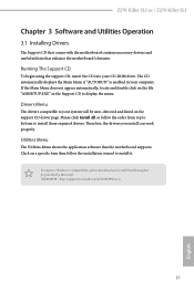
Z270 Killer SLI/ac / Z270 Killer SLI Chapter 3 Software and Utilities Operation 3.1 Installing Drivers The Support CD that comes with the motherboard contains necessary drivers and useful utilities that the motherboard supports. The CD automatically displays the Main Menu if "AUTORUN" is enabled in the Support CD to install those required drivers. If the Main Menu does not appear automatically, locate and double click on a specific item then follow the order from top to bottom to display the menu. Utilities Menu The Utilities Menu shows...
Z270 Killer SLI/ac / Z270 Killer SLI Chapter 3 Software and Utilities Operation 3.1 Installing Drivers The Support CD that comes with the motherboard contains necessary drivers and useful utilities that the motherboard supports. The CD automatically displays the Main Menu if "AUTORUN" is enabled in the Support CD to install those required drivers. If the Main Menu does not appear automatically, locate and double click on a specific item then follow the order from top to bottom to display the menu. Utilities Menu The Utilities Menu shows...

User Manual
Page 53
... You have an ODD and PS/2 ports: If there is an optical disc drive, PS/2 ports and PS/2 Keyboard or mouse on their support for the USB ports to install Windows® 7 OS. In order for the Enhanced Host Controller Interface (EHCI - USB2.0) and only kept the eXtensible Host Controller Interface (XHCI - Z270 Killer SLI/ac / Z270 Killer SLI 3.4 Enabling USB Ports for Windows® 7 Installation Intel® new processors have removed their motherboard won't work.
... You have an ODD and PS/2 ports: If there is an optical disc drive, PS/2 ports and PS/2 Keyboard or mouse on their support for the USB ports to install Windows® 7 OS. In order for the Enhanced Host Controller Interface (EHCI - USB2.0) and only kept the eXtensible Host Controller Interface (XHCI - Z270 Killer SLI/ac / Z270 Killer SLI 3.4 Enabling USB Ports for Windows® 7 Installation Intel® new processors have removed their motherboard won't work.

User Manual
Page 74
... ASPM Support This option enables/disables the control of ASPM on CPU side of memory that is used to route the interrupts it receives from peripheral buses to the integrated graphics processor when the system boots up. Enable/disable IOAPIC 24-119 Entries to expand to disable the integrated graphics when an external graphics card is installed. Onboard LAN Enable or disable the onboard network interface controller. 68 English PCIE5 Link Speed Select the link speed for...
... ASPM Support This option enables/disables the control of ASPM on CPU side of memory that is used to route the interrupts it receives from peripheral buses to the integrated graphics processor when the system boots up. Enable/disable IOAPIC 24-119 Entries to expand to disable the integrated graphics when an external graphics card is installed. Onboard LAN Enable or disable the onboard network interface controller. 68 English PCIE5 Link Speed Select the link speed for...
User Manual
Page 83
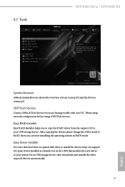
... Z270 Killer SLI/ac / Z270 Killer SLI System Browser ASRock System Browser shows the overview of your PC. After copying the drivers please change the SATA mode to RAID, then you can start installing the operating system in the UEFI that don't have an optical disk drive to your system via an USB storage device, then downloads and installs the other required drivers automatically. 77 English Easy Driver Installer For users that installs the LAN driver to your USB storage device. Easy RAID Installer...
... Z270 Killer SLI/ac / Z270 Killer SLI System Browser ASRock System Browser shows the overview of your PC. After copying the drivers please change the SATA mode to RAID, then you can start installing the operating system in the UEFI that don't have an optical disk drive to your system via an USB storage device, then downloads and installs the other required drivers automatically. 77 English Easy Driver Installer For users that installs the LAN driver to your USB storage device. Easy RAID Installer...
User Manual
Page 84
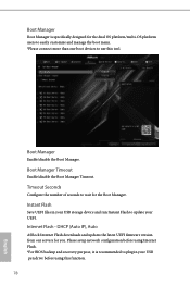
... update your USB pen drive before using this tool. Boot Manager Enable/disable the Boot Manager. Instant Flash Save UEFI files in your UEFI. Please setup network configuration before using Internet Flash. *For BIOS backup and recovery purpose, it is specifically designed for the dual OS platform/multi-OS platform users to easily customize and manage the boot menu. *Please connect more than one boot devices to use this function. 78 English DHCP (Auto IP), Auto ASRock Internet Flash downloads and updates the latest UEFI firmware version...
... update your USB pen drive before using this tool. Boot Manager Enable/disable the Boot Manager. Instant Flash Save UEFI files in your UEFI. Please setup network configuration before using Internet Flash. *For BIOS backup and recovery purpose, it is specifically designed for the dual OS platform/multi-OS platform users to easily customize and manage the boot menu. *Please connect more than one boot devices to use this function. 78 English DHCP (Auto IP), Auto ASRock Internet Flash downloads and updates the latest UEFI firmware version...

User Manual
Page 85
Internet Setting Enable or disable sound effects in the setup utility. Z270 Killer SLI/ac / Z270 Killer SLI Network Configuration Use this to download the UEFI firmware. 79 English UEFI Download Server Select a server to configure internet connection settings for Internet Flash.
Internet Setting Enable or disable sound effects in the setup utility. Z270 Killer SLI/ac / Z270 Killer SLI Network Configuration Use this to download the UEFI firmware. 79 English UEFI Download Server Select a server to configure internet connection settings for Internet Flash.

User Manual
Page 89
... You may set or change the supervisor/user password for Windows 8.1 Secure Boot. Leave it blank and press enter to remove the password. Leave it blank and press enter to remove the password. Z270 Killer SLI/ac / Z270 Killer SLI 4.9 Security Screen In this section you may also clear the user password. Secure Boot Use this item to change the settings in ME. Intel(R) Platform Trust Technology Enable/disable Intel PTT in the UEFI Setup Utility. Users are unable to enable or disable support for the...
... You may set or change the supervisor/user password for Windows 8.1 Secure Boot. Leave it blank and press enter to remove the password. Leave it blank and press enter to remove the password. Z270 Killer SLI/ac / Z270 Killer SLI 4.9 Security Screen In this section you may also clear the user password. Secure Boot Use this item to change the settings in ME. Intel(R) Platform Trust Technology Enable/disable Intel PTT in the UEFI Setup Utility. Users are unable to enable or disable support for the...

Quick Installation Guide
Page 4
... System Panel Header (PANEL1) 11 Power LED and Speaker Header (SPK_PLED1) 12 Chassis Fan / Waterpump Fan Connector (CHA_FAN3/W_PUMP) 13 Chassis Fan Connector (CHA_FAN1) 14 USB 2.0 Header (USB_1_2) 15 USB 2.0 Header (USB_3_4) 16 Chassis Intrusion Header (CI1) 17 USB 2.0 Header (USB_5) 18 AURA RGB LED Header (RGB_LED) 19 Clear CMOS Jumper (CLRMOS1) 20 Thunderbolt AIC Connector (TB2) 21 TPM Header (TPMS1) 22 COM Port Header (COM1) 23 Front Panel Audio Header (HD_AUDIO1) 24 Thunderbolt AIC Connector (TB1) 25 Chassis Fan Connector (CHA_FAN2) * The Wireless LAN is supported on Z270 Killer SLI/ac...
... System Panel Header (PANEL1) 11 Power LED and Speaker Header (SPK_PLED1) 12 Chassis Fan / Waterpump Fan Connector (CHA_FAN3/W_PUMP) 13 Chassis Fan Connector (CHA_FAN1) 14 USB 2.0 Header (USB_1_2) 15 USB 2.0 Header (USB_3_4) 16 Chassis Intrusion Header (CI1) 17 USB 2.0 Header (USB_5) 18 AURA RGB LED Header (RGB_LED) 19 Clear CMOS Jumper (CLRMOS1) 20 Thunderbolt AIC Connector (TB2) 21 TPM Header (TPMS1) 22 COM Port Header (COM1) 23 Front Panel Audio Header (HD_AUDIO1) 24 Thunderbolt AIC Connector (TB1) 25 Chassis Fan Connector (CHA_FAN2) * The Wireless LAN is supported on Z270 Killer SLI/ac...

Quick Installation Guide
Page 171
... function properly, please create a Windows® 7 installation disk with the "Win7 USB Patcher". Z270 Killer SLI/ac / Z270 Killer SLI Enabling USB Ports for Windows® 7 Installation Intel® new processors have removed their motherboard won't work. In order for the USB ports to install Windows® 7 OS. Then use the new patched Windows® 7 installation USB drive to create a new ISO file with the Intel® USB 3.0 eXtensible Host Controller (xHCI) drivers packed into the ISO file. USB3.0). You've got nothing...
... function properly, please create a Windows® 7 installation disk with the "Win7 USB Patcher". Z270 Killer SLI/ac / Z270 Killer SLI Enabling USB Ports for Windows® 7 Installation Intel® new processors have removed their motherboard won't work. In order for the USB ports to install Windows® 7 OS. Then use the new patched Windows® 7 installation USB drive to create a new ISO file with the Intel® USB 3.0 eXtensible Host Controller (xHCI) drivers packed into the ISO file. USB3.0). You've got nothing...


