
User Manual
Page 4
...1.2 Specifications 2 1.3 Motherboard Layout 8 1.4 I/O Panel 10 Chapter 2 Installation 12 2.1 Installing the CPU 13 2.2 Installing the CPU Fan and Heatsink 16 2.3 Installing Memory Modules (DIMM) 17 2.4 Expansion Slots (PCI Express Slots) 19 2.5 Jumpers Setup 20 2.6 Onboard Headers and Connectors 21 2.7 SLITM and Quad SLITM Operation Guide 26 2.7.1 Installing Two SLITM-Ready Graphics Cards 26 2.7.2 Driver Installation and Setup 28 2.8 CrossFireXTM , 3-Way CrossFireXTM and Quad CrossFireXTM Operation Guide 29 2.8.1 Installing Two CrossFireXTM-Ready Graphics Cards 29...
...1.2 Specifications 2 1.3 Motherboard Layout 8 1.4 I/O Panel 10 Chapter 2 Installation 12 2.1 Installing the CPU 13 2.2 Installing the CPU Fan and Heatsink 16 2.3 Installing Memory Modules (DIMM) 17 2.4 Expansion Slots (PCI Express Slots) 19 2.5 Jumpers Setup 20 2.6 Onboard Headers and Connectors 21 2.7 SLITM and Quad SLITM Operation Guide 26 2.7.1 Installing Two SLITM-Ready Graphics Cards 26 2.7.2 Driver Installation and Setup 28 2.8 CrossFireXTM , 3-Way CrossFireXTM and Quad CrossFireXTM Operation Guide 29 2.8.1 Installing Two CrossFireXTM-Ready Graphics Cards 29...
User Manual
Page 5
...3 Software and Utilities Operation 39 3.1 Installing Drivers 39 3.2 A-Tuning 40 3.2.1 Installing A-Tuning 40 3.2.2 Using A-Tuning 40 3.3 ASRock Live Update & APP Shop 43 3.3.1 UI Overview 43 3.3.2 Apps 44 3.3.3 BIOS & Drivers 47 3.3.4 Setting 48 3.4 Enabling USB Ports for Windows® 7 Installation 49 3.5 ASRock AURA RGB LED 52 Chapter 4 UEFI SETUP UTILITY 53 4.1 Introduction 53 4.2 EZ Mode 54 4.3 Advanced Mode 55 4.3.1 UEFI Menu Bar 55 4.3.2 Navigation Keys 56 4.4 Main Screen 57 4.5 OC Tweaker Screen 58 4.6 Advanced Screen 65 4.6.1 CPU Configuration...
...3 Software and Utilities Operation 39 3.1 Installing Drivers 39 3.2 A-Tuning 40 3.2.1 Installing A-Tuning 40 3.2.2 Using A-Tuning 40 3.3 ASRock Live Update & APP Shop 43 3.3.1 UI Overview 43 3.3.2 Apps 44 3.3.3 BIOS & Drivers 47 3.3.4 Setting 48 3.4 Enabling USB Ports for Windows® 7 Installation 49 3.5 ASRock AURA RGB LED 52 Chapter 4 UEFI SETUP UTILITY 53 4.1 Introduction 53 4.2 EZ Mode 54 4.3 Advanced Mode 55 4.3.1 UEFI Menu Bar 55 4.3.2 Navigation Keys 56 4.4 Main Screen 57 4.5 OC Tweaker Screen 58 4.6 Advanced Screen 65 4.6.1 CPU Configuration...
User Manual
Page 7
...VGA cards and CPU support list on ASRock's website without notice. Because the motherboard specifications and the BIOS software might be updated, the content of this documentation occur, the updated version will be available on ASRock's website as well. ASRock website http://www.asrock.com. 1.1 Package Contents • ASRock Z270 Extreme4 Motherboard (ATX Form Factor) • ASRock Z270 Extreme4 Quick Installation Guide • ASRock Z270 Extreme4 Support CD • 1 x I/O Panel Shield • 4 x Serial ATA (SATA) Data Cables (Optional) • 1 x ASRock SLI_HB_Bridge_2S Card...
...VGA cards and CPU support list on ASRock's website without notice. Because the motherboard specifications and the BIOS software might be updated, the content of this documentation occur, the updated version will be available on ASRock's website as well. ASRock website http://www.asrock.com. 1.1 Package Contents • ASRock Z270 Extreme4 Motherboard (ATX Form Factor) • ASRock Z270 Extreme4 Quick Installation Guide • ASRock Z270 Extreme4 Support CD • 1 x I/O Panel Shield • 4 x Serial ATA (SATA) Data Cables (Optional) • 1 x ASRock SLI_HB_Bridge_2S Card...
User Manual
Page 11
...; OptaneTM Technology ** Supports NVMe SSD as boot disks ** Supports ASRock U.2 Kit Connector • 1 x COM Port Header • 1 x TPM Header • 1 x Power LED and Speaker Header • 1 x AURA RGB LED Header • 1 x CPU Fan Connector (4-pin) * The CPU Fan Connector supports the CPU fan of them is supported English 5 If either one of maximum 1A (12W) fan power. • 1 x CPU Optional/Water Pump Fan Connector (4-pin) • 2 x Chassis Fan Connectors (4-pin) (Smart Fan Speed Con- If either one Thunderbolt AIC Card is in use , the others will be disabled. * M2_2...
...; OptaneTM Technology ** Supports NVMe SSD as boot disks ** Supports ASRock U.2 Kit Connector • 1 x COM Port Header • 1 x TPM Header • 1 x Power LED and Speaker Header • 1 x AURA RGB LED Header • 1 x CPU Fan Connector (4-pin) * The CPU Fan Connector supports the CPU fan of them is supported English 5 If either one of maximum 1A (12W) fan power. • 1 x CPU Optional/Water Pump Fan Connector (4-pin) • 2 x Chassis Fan Connectors (4-pin) (Smart Fan Speed Con- If either one Thunderbolt AIC Card is in use , the others will be disabled. * M2_2...

User Manual
Page 12
... supply is required. bit (For 6th Gen Intel® CPU) * To install Windows® 7 OS, a modified installation disk with multilingual GUI support (1 x Main BIOS and 1 x Backup BIOS) • Supports Secure Backup UEFI Technology • ACPI 6.0 Compliant wake up events • SMBIOS 2.7 Support • CPU, GT_CPU, DRAM, VPP, PCH 1.0V, VCCIO, VCCST, VCCSA, VCCPLL Voltage Multi-adjustment Hardware Monitor OS • CPU / Chassis / CPU Optional/Water Pump / Chassis Optional/Water Pump temperature sensing • CPU / Chassis / CPU Optional/Water Pump / Chassis Optional/Water Pump Fan...
... supply is required. bit (For 6th Gen Intel® CPU) * To install Windows® 7 OS, a modified installation disk with multilingual GUI support (1 x Main BIOS and 1 x Backup BIOS) • Supports Secure Backup UEFI Technology • ACPI 6.0 Compliant wake up events • SMBIOS 2.7 Support • CPU, GT_CPU, DRAM, VPP, PCH 1.0V, VCCIO, VCCST, VCCSA, VCCPLL Voltage Multi-adjustment Hardware Monitor OS • CPU / Chassis / CPU Optional/Water Pump / Chassis Optional/Water Pump temperature sensing • CPU / Chassis / CPU Optional/Water Pump / Chassis Optional/Water Pump Fan...
User Manual
Page 15
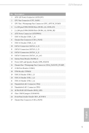
... SATA3 Connectors (SATA3_2_3) 12 SATA3 Connectors (SATA3_0_1) 13 SATA3 Connectors (SATA3_A1_A2) 14 System Panel Header (PANEL1) 15 Power LED and Speaker Header (SPK_PLED1) 16 Chassis Fan / Waterpump Fan Connector (CHA_FAN3/W_PUMP) 17 COM Port Header (COM1) 18 TPM Header (TPMS1) 19 USB 2.0 Header (USB_1_2) 20 USB 2.0 Header (USB_3_4) 21 USB 2.0 Header (USB_5_6) 22 Thunderbolt AIC Connector (TB2) 23 Thunderbolt AIC Connector (TB1) 24 AURA RGB LED Header (RGB_LED) 25 Clear CMOS Jumper (CLRMOS1) 26 Front Panel Audio Header (HD_AUDIO1) 27 Chassis Fan Connector (CHA_FAN1) 9 English Z270 Extreme4...
... SATA3 Connectors (SATA3_2_3) 12 SATA3 Connectors (SATA3_0_1) 13 SATA3 Connectors (SATA3_A1_A2) 14 System Panel Header (PANEL1) 15 Power LED and Speaker Header (SPK_PLED1) 16 Chassis Fan / Waterpump Fan Connector (CHA_FAN3/W_PUMP) 17 COM Port Header (COM1) 18 TPM Header (TPMS1) 19 USB 2.0 Header (USB_1_2) 20 USB 2.0 Header (USB_3_4) 21 USB 2.0 Header (USB_5_6) 22 Thunderbolt AIC Connector (TB2) 23 Thunderbolt AIC Connector (TB1) 24 AURA RGB LED Header (RGB_LED) 25 Clear CMOS Jumper (CLRMOS1) 26 Front Panel Audio Header (HD_AUDIO1) 27 Chassis Fan Connector (CHA_FAN1) 9 English Z270 Extreme4...
User Manual
Page 25
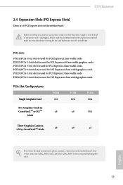
... connect a chassis fan to the motherboard's chassis fan connector (CHA_FAN1, CHA_FAN2 or CHA_FAN3 ) when using multiple graphics cards. 19 Before installing an expansion card, please make necessary hardware settings for PCI Express x1 lane width cards. Please read the documentation of the expansion card and make sure that the power supply is switched off or the power cord is used for PCI Express x4 lane width graphics cards. PCIE5 (PCIe 3.0 x1 slot) is used for PCI Express x1 lane width cards. Z270 Extreme4 2.4 Expansion Slots (PCI Express Slots...
... connect a chassis fan to the motherboard's chassis fan connector (CHA_FAN1, CHA_FAN2 or CHA_FAN3 ) when using multiple graphics cards. 19 Before installing an expansion card, please make necessary hardware settings for PCI Express x1 lane width cards. Please read the documentation of the expansion card and make sure that the power supply is switched off or the power cord is used for PCI Express x4 lane width graphics cards. PCIE5 (PCIe 3.0 x1 slot) is used for PCI Express x1 lane width cards. Z270 Extreme4 2.4 Expansion Slots (PCI Express Slots...
User Manual
Page 27
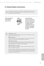
... LED, speaker and etc. HDLED (Hard Drive Activity LED): Connect to the power status indicator on when the hard drive is in S1/S3 sleep state. English 21 Note the positive and negative pins before connecting the cables. The LED is operating. Press the reset switch to restart the computer if the computer freezes and fails to the power switch on the chassis front panel. You may differ by chassis. Z270 Extreme4 2.6 Onboard Headers and Connectors Onboard headers...
... LED, speaker and etc. HDLED (Hard Drive Activity LED): Connect to the power status indicator on when the hard drive is in S1/S3 sleep state. English 21 Note the positive and negative pins before connecting the cables. The LED is operating. Press the reset switch to restart the computer if the computer freezes and fails to the power switch on the chassis front panel. You may differ by chassis. Z270 Extreme4 2.6 Onboard Headers and Connectors Onboard headers...
User Manual
Page 28
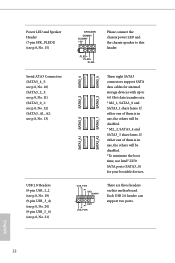
... is in use Intel® Z270 SATA ports (SATA3_0) for internal storage devices with up to this motherboard. SATA3_5 SATA3_4 SATA3_3 SATA3_2 SATA3_A2 SATA3_1 SATA3_A1 SATA3_0 These eight SATA3 connectors support SATA data cables for your bootable devices. Each USB 2.0 header can support two ports. Please connect the chassis power LED and the chassis speaker to 6.0 Gb/s data transfer rate. * M2_1, SATA3_0 and SATA3_1 share lanes. Power LED and Speaker Header (7-pin SPK_PLED1) (see p.8, No. 15) Serial ATA3 Connectors (SATA3_4_5...
... is in use Intel® Z270 SATA ports (SATA3_0) for internal storage devices with up to this motherboard. SATA3_5 SATA3_4 SATA3_3 SATA3_2 SATA3_A2 SATA3_1 SATA3_A1 SATA3_0 These eight SATA3 connectors support SATA data cables for your bootable devices. Each USB 2.0 header can support two ports. Please connect the chassis power LED and the chassis speaker to 6.0 Gb/s data transfer rate. * M2_1, SATA3_0 and SATA3_1 share lanes. Power LED and Speaker Header (7-pin SPK_PLED1) (see p.8, No. 15) Serial ATA3 Connectors (SATA3_4_5...

User Manual
Page 32
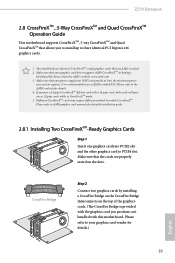
... for details. 2.7.1 Installing Two SLITM-Ready Graphics Cards Step 1 Insert one graphics card into PCIE2 slot and the other graphics card to the PCI Express graphics cards. 26 English Step 2 If required, connect the auxiliary power source to PCIE4 slot. Requirements 1. You should only use identical SLITM-ready graphics cards that allows you to install up to use a NVIDIA® certified PSU. 2.7 SLITM and Quad SLITM Operation Guide This motherboard supports NVIDIA®...
... for details. 2.7.1 Installing Two SLITM-Ready Graphics Cards Step 1 Insert one graphics card into PCIE2 slot and the other graphics card to the PCI Express graphics cards. 26 English Step 2 If required, connect the auxiliary power source to PCIE4 slot. Requirements 1. You should only use identical SLITM-ready graphics cards that allows you to install up to use a NVIDIA® certified PSU. 2.7 SLITM and Quad SLITM Operation Guide This motherboard supports NVIDIA®...
User Manual
Page 35
... detailed installation guide. 2.8.1 Installing Two CrossFireXTM-Ready Graphics Cards Step 1 Insert one graphics card into PCIE2 slot and the other graphics card to three identical PCI Express x16 graphics cards. 1. If you to install up to PCIE4 slot. Please refer to enable CrossFireXTM. Download the drivers from the AMD's website: www.amd.com 3. Different CrossFireXTM cards may require different methods to your system requires. Z270 Extreme4 2.8 CrossFireXTM , 3-Way CrossFireXTM and Quad CrossFireXTM Operation Guide This motherboard supports...
... detailed installation guide. 2.8.1 Installing Two CrossFireXTM-Ready Graphics Cards Step 1 Insert one graphics card into PCIE2 slot and the other graphics card to three identical PCI Express x16 graphics cards. 1. If you to install up to PCIE4 slot. Please refer to enable CrossFireXTM. Download the drivers from the AMD's website: www.amd.com 3. Different CrossFireXTM cards may require different methods to your system requires. Z270 Extreme4 2.8 CrossFireXTM , 3-Way CrossFireXTM and Quad CrossFireXTM Operation Guide This motherboard supports...

User Manual
Page 38
... recommend using this utility to uninstall any VGA drivers installed in the Windows® system tray. Please check AMD's website for AMD driver updates. Then select Enable AMD CrossFireX and click Apply. English 32 Step 2 Remove the AMD drivers if you have any previously installed Catalyst drivers prior to your system. 2.8.3 Driver Installation and Setup Step 1 Power on your computer. Step 3 Install the required drivers and CATALYST Control Center then restart your computer and boot...
... recommend using this utility to uninstall any VGA drivers installed in the Windows® system tray. Please check AMD's website for AMD driver updates. Then select Enable AMD CrossFireX and click Apply. English 32 Step 2 Remove the AMD drivers if you have any previously installed Catalyst drivers prior to your system. 2.8.3 Driver Installation and Setup Step 1 Power on your computer. Step 3 Install the required drivers and CATALYST Control Center then restart your computer and boot...
User Manual
Page 45
... a specific item then follow the order from top to bottom to your system will be auto-detected and listed on the file "ASRSETUP.EXE" in your CD-ROM drive. To improve Windows 7 compatibility, please download and install the following hot fix provided by Microsoft. Therefore, the drivers you install can work properly. Z270 Extreme4 Chapter 3 Software and Utilities Operation 3.1 Installing Drivers The Support CD that comes with the motherboard contains necessary drivers...
... a specific item then follow the order from top to bottom to your system will be auto-detected and listed on the file "ASRSETUP.EXE" in your CD-ROM drive. To improve Windows 7 compatibility, please download and install the following hot fix provided by Microsoft. Therefore, the drivers you install can work properly. Z270 Extreme4 Chapter 3 Software and Utilities Operation 3.1 Installing Drivers The Support CD that comes with the motherboard contains necessary drivers...

User Manual
Page 55
...® USB 3.0 eXtensible Host Controller (xHCI) drivers packed into the ISO file. Z270 Extreme4 3.4 Enabling USB Ports for Windows® 7 Installation Intel® new processors have removed removed their motherboard won't work. USB2.0) and only kept the eXtensible Host Controller Interface (XHCI - In order for the Enhanced Host Controller Interface (EHCI - Requirements • A Windows® 7 installation disk or USB drive • A Windows® PC • Win7 USB Patcher (included in the ASRock Support CD or downloaded from website...
...® USB 3.0 eXtensible Host Controller (xHCI) drivers packed into the ISO file. Z270 Extreme4 3.4 Enabling USB Ports for Windows® 7 Installation Intel® new processors have removed removed their motherboard won't work. USB2.0) and only kept the eXtensible Host Controller Interface (XHCI - In order for the Enhanced Host Controller Interface (EHCI - Requirements • A Windows® 7 installation disk or USB drive • A Windows® PC • Win7 USB Patcher (included in the ASRock Support CD or downloaded from website...

User Manual
Page 75
... speed for PCIE4. PCH PCIE ASPM Support This option enables/disables the ASPM support for enhanced PCI Express power saving in OS. IGPU Multi-Monitor Select disable to disable the integrated graphics when an external graphics card is used to route the interrupts it receives from peripheral buses to the integrated graphics processor when the system boots up. Select enable to PIROI-PIROX. PCI Express Native Control Select Enable for all CPU downstream devices. DMI ASPM Support This option enables/disables...
... speed for PCIE4. PCH PCIE ASPM Support This option enables/disables the ASPM support for enhanced PCI Express power saving in OS. IGPU Multi-Monitor Select disable to disable the integrated graphics when an external graphics card is used to route the interrupts it receives from peripheral buses to the integrated graphics processor when the system boots up. Select enable to PIROI-PIROX. PCI Express Native Control Select Enable for all CPU downstream devices. DMI ASPM Support This option enables/disables...

User Manual
Page 80
Serial Port Address Select the address of the Serial port. PS2 Y-Cable Enable the PS2 Y-Cable or set this option to Auto. 74 English 4.6.5 Super IO Configuration Serial Port Enable or disable the Serial port.
Serial Port Address Select the address of the Serial port. PS2 Y-Cable Enable the PS2 Y-Cable or set this option to Auto. 74 English 4.6.5 Super IO Configuration Serial Port Enable or disable the Serial port.

User Manual
Page 85
... disk drive to install the drivers from the support CD to your current PC and the devices connected. 4.7 Tools Z270 Extreme4 System Browser ASRock System Browser shows the overview of your system via an USB storage device, then downloads and installs the other required drivers automatically. 79 English UEFI Tech Service Contact ASRock Tech Service if you can start installing the operating system in the UEFI that installs the LAN driver to your PC. Please setup network configuration before using UEFI...
... disk drive to install the drivers from the support CD to your current PC and the devices connected. 4.7 Tools Z270 Extreme4 System Browser ASRock System Browser shows the overview of your system via an USB storage device, then downloads and installs the other required drivers automatically. 79 English UEFI Tech Service Contact ASRock Tech Service if you can start installing the operating system in the UEFI that installs the LAN driver to your PC. Please setup network configuration before using UEFI...
User Manual
Page 86
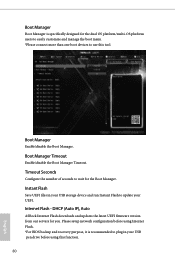
... UEFI. Please setup network configuration before using Internet Flash. *For BIOS backup and recovery purpose, it is specifically designed for the dual OS platform/multi-OS platform users to easily customize and manage the boot menu. *Please connect more than one boot devices to wait for you. Timeout Seconds Configure the number of seconds to use this function. 80 English Boot Manager Timeout Enable/disable the Boot Manager Timeout. DHCP (Auto IP), Auto ASRock Internet Flash downloads...
... UEFI. Please setup network configuration before using Internet Flash. *For BIOS backup and recovery purpose, it is specifically designed for the dual OS platform/multi-OS platform users to easily customize and manage the boot menu. *Please connect more than one boot devices to wait for you. Timeout Seconds Configure the number of seconds to use this function. 80 English Boot Manager Timeout Enable/disable the Boot Manager Timeout. DHCP (Auto IP), Auto ASRock Internet Flash downloads...
User Manual
Page 87
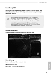
Use "Secure Backup UEFI" to duplicate a working ROM image to update the backup BIOS manually. However if the active BIOS is currently activated. Internet Setting Enable or disable sound effects in the setup utility. Normally, the system will take over. Network Configuration Use this to ensure normal system operation. Z270 Extreme4 Secure Backup UEFI Whenever one of the ROM images are not able to the secondary flash ROM. For safety issues, users are outdated or...
Use "Secure Backup UEFI" to duplicate a working ROM image to update the backup BIOS manually. However if the active BIOS is currently activated. Internet Setting Enable or disable sound effects in the setup utility. Normally, the system will take over. Network Configuration Use this to ensure normal system operation. Z270 Extreme4 Secure Backup UEFI Whenever one of the ROM images are not able to the secondary flash ROM. For safety issues, users are outdated or...

User Manual
Page 91
... administrator account. Intel(R) Platform Trust Technology Enable/disable Intel PTT in the UEFI Setup Utility. Only the administrator has authority to remove the password. User Password Set or change the settings in ME. Users are unable to remove the password. Disable this item to use discrete TPM Module. 85 English Z270 Extreme4 4.9 Security Screen In this section you may also clear the user password. Leave it blank and press enter to change the supervisor/user password for Windows 8.1 Secure Boot.
... administrator account. Intel(R) Platform Trust Technology Enable/disable Intel PTT in the UEFI Setup Utility. Only the administrator has authority to remove the password. User Password Set or change the settings in ME. Users are unable to remove the password. Disable this item to use discrete TPM Module. 85 English Z270 Extreme4 4.9 Security Screen In this section you may also clear the user password. Leave it blank and press enter to change the supervisor/user password for Windows 8.1 Secure Boot.


