RAID Installation Guide
Page 7
Go to Advanced Storage Coniguration and set the option SATA Mode Selection to complete the process. STEP 2: Use ASRock Easy RAID Installer Easy RAID Installer can copy the RAID driver from a support CD to your USB lash drive into a USB port. Plug in your USB storage device with RAID functions, please follow the procedures below. Enter UEFI SETUP UTILITY Tool and highlight "Easy RAID Installer". Follow the onscreen instruction to [RAID]. STEP 1: Setting the BIOS RAID Items After installing the hard disk drives, please set RAID coniguration. Please note that this...
Go to Advanced Storage Coniguration and set the option SATA Mode Selection to complete the process. STEP 2: Use ASRock Easy RAID Installer Easy RAID Installer can copy the RAID driver from a support CD to your USB lash drive into a USB port. Plug in your USB storage device with RAID functions, please follow the procedures below. Enter UEFI SETUP UTILITY Tool and highlight "Easy RAID Installer". Follow the onscreen instruction to [RAID]. STEP 1: Setting the BIOS RAID Items After installing the hard disk drives, please set RAID coniguration. Please note that this...
RAID Installation Guide
Page 18
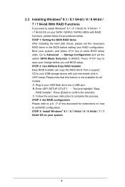
... a USB lash disk or copy the iles from ASRock's motherboard support CD. (Please copy the iles under the following directory: 32 bit: ..\i386\Win7_Intel.. 64-bit: ..\AMD64\Win7-64_Intel.. Installing Windows® on a HDD larger than 2TB in RAID mode Windows® 7 / 8 / 8.1 does not support HDD's larger than 2TB. STEP 2: Install Windows® 7 64-bit / 8 64-bit / 8.1 64bit OS Press to launch boot menu at system POST and choose the item "UEFI:" to use Windows...
... a USB lash disk or copy the iles from ASRock's motherboard support CD. (Please copy the iles under the following directory: 32 bit: ..\i386\Win7_Intel.. 64-bit: ..\AMD64\Win7-64_Intel.. Installing Windows® on a HDD larger than 2TB in RAID mode Windows® 7 / 8 / 8.1 does not support HDD's larger than 2TB. STEP 2: Install Windows® 7 64-bit / 8 64-bit / 8.1 64bit OS Press to launch boot menu at system POST and choose the item "UEFI:" to use Windows...

User Manual
Page 4
...1.3 Motherboard Layout 6 1.4 I/O Panel 8 Chapter 2 Installation 10 2.1 Installing the CPU 11 2.2 Installing the CPU Fan and Heatsink 14 2.3 Installation of Memory Modules (DIMM) 15 2.4 Expansion Slots (PCI Express Slots) 17 2.5 Jumpers Setup 18 2.6 Onboard Headers and Connectors 19 2.7 Smart Switches 24 2.8 Dr. Debug 25 2.9 SLITM and Quad SLITM Operation Guide 27 2.9.1 Installing Two SLITM-Ready Graphics Cards 27 2.9.2 Driver Installation and Setup 29 2.10 CrossFireXTM and Quad CrossFireXTM Operation Guide 30 2.10.1 Installing Two CrossFireXTM-Ready Graphics Cards...
...1.3 Motherboard Layout 6 1.4 I/O Panel 8 Chapter 2 Installation 10 2.1 Installing the CPU 11 2.2 Installing the CPU Fan and Heatsink 14 2.3 Installation of Memory Modules (DIMM) 15 2.4 Expansion Slots (PCI Express Slots) 17 2.5 Jumpers Setup 18 2.6 Onboard Headers and Connectors 19 2.7 Smart Switches 24 2.8 Dr. Debug 25 2.9 SLITM and Quad SLITM Operation Guide 27 2.9.1 Installing Two SLITM-Ready Graphics Cards 27 2.9.2 Driver Installation and Setup 29 2.10 CrossFireXTM and Quad CrossFireXTM Operation Guide 30 2.10.1 Installing Two CrossFireXTM-Ready Graphics Cards...

User Manual
Page 10
... PCI Express module up to Gen3 x4 (32 Gb/s) Connector • 1 x COM Port Header • 1 x TPM Header • 1 x Power LED Header • 2 x CPU Fan Connectors (1 x 4-pin, 1 x 3-pin) • 2 x Chassis Fan Connectors (1 x 4-pin, 1 x 3-pin) (Smart Fan Speed Control) • 1 x Power Fan Connector (3-pin) • 1 x 24 pin ATX Power Connector • 1 x 8 pin 12V Power Connector (Hi-Density Power Connector) • 1 x HDD Saver Connector • 1 x PCIe Power Connector • 1 x Front Panel Audio Connector • 1 x hunderbolt AIC Connector • 2 x USB 2.0 Headers (support...
... PCI Express module up to Gen3 x4 (32 Gb/s) Connector • 1 x COM Port Header • 1 x TPM Header • 1 x Power LED Header • 2 x CPU Fan Connectors (1 x 4-pin, 1 x 3-pin) • 2 x Chassis Fan Connectors (1 x 4-pin, 1 x 3-pin) (Smart Fan Speed Control) • 1 x Power Fan Connector (3-pin) • 1 x 24 pin ATX Power Connector • 1 x 8 pin 12V Power Connector (Hi-Density Power Connector) • 1 x HDD Saver Connector • 1 x PCIe Power Connector • 1 x Front Panel Audio Connector • 1 x hunderbolt AIC Connector • 2 x USB 2.0 Headers (support...
User Manual
Page 13
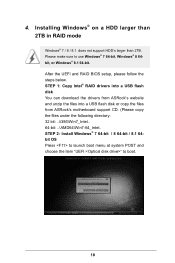
... (SATA_PWR_1) 12 SATA3 Connectors (S_SATA3_2_3) 13 SATA3 Connectors (SATA3_0_3) 14 SATA3 Connectors (SATA3_1_4) 15 SATA3 Connectors (SATA3_2_5) 16 Power LED Header (PLED1) 17 System Panel Header (PANEL1) 18 Clear CMOS Jumper (CLRCMOS1) 19 Chassis Speaker Header (SPEAKER1) 20 Chassis Fan Connector (CHA_FAN1) 21 USB 2.0 Header (USB7_8) 22 USB 2.0 Header (USB5_6) 23 COM Port Header (COM1) 24 hunderbolt AIC Connector (TBT1) 25 PCIe Power Connector (PCIE_PWR1) 26 Front Panel Audio Header (HD_AUDIO1) 27 BIOS Selection Switch (BIOS_SEL1) 28 Power Fan Connector (PWR_FAN1) X99M Extreme4 English 7 No...
... (SATA_PWR_1) 12 SATA3 Connectors (S_SATA3_2_3) 13 SATA3 Connectors (SATA3_0_3) 14 SATA3 Connectors (SATA3_1_4) 15 SATA3 Connectors (SATA3_2_5) 16 Power LED Header (PLED1) 17 System Panel Header (PANEL1) 18 Clear CMOS Jumper (CLRCMOS1) 19 Chassis Speaker Header (SPEAKER1) 20 Chassis Fan Connector (CHA_FAN1) 21 USB 2.0 Header (USB7_8) 22 USB 2.0 Header (USB5_6) 23 COM Port Header (COM1) 24 hunderbolt AIC Connector (TBT1) 25 PCIe Power Connector (PCIE_PWR1) 26 Front Panel Audio Header (HD_AUDIO1) 27 BIOS Selection Switch (BIOS_SEL1) 28 Power Fan Connector (PWR_FAN1) X99M Extreme4 English 7 No...

User Manual
Page 26
... 1 GND P+ PUSB_PWR Besides four USB 2.0 ports on the I/O panel, there are two headers on this motherboard. SATA3_5 SATA3_4 SATA3_2 SATA3_1 USB 2.0 Headers (9-pin USB5_6) (see p.6, No. 22) (9-pin USB7_8) (see p.6, No. 21) USB 3.0 Header (19-pin USB3_5_6) (see p.6, No. 15) SATA3_0 S_SATA3_2 S_SATA3_0 1 PLEDPLED+ PLED+ SATA3_3 S_SATA3_3 S_SATA3_1 Please connect the chassis power LED to this motherboard. hese ten SATA3 connectors support SATA data cables for internal storage devices with up to indicate the...
... 1 GND P+ PUSB_PWR Besides four USB 2.0 ports on the I/O panel, there are two headers on this motherboard. SATA3_5 SATA3_4 SATA3_2 SATA3_1 USB 2.0 Headers (9-pin USB5_6) (see p.6, No. 22) (9-pin USB7_8) (see p.6, No. 21) USB 3.0 Header (19-pin USB3_5_6) (see p.6, No. 15) SATA3_0 S_SATA3_2 S_SATA3_0 1 PLEDPLED+ PLED+ SATA3_3 S_SATA3_3 S_SATA3_1 Please connect the chassis power LED to this motherboard. hese ten SATA3 connectors support SATA data cables for internal storage devices with up to indicate the...

User Manual
Page 28
To use a 20-pin ATX power supply, please plug it along Pin 1 and Pin 5. Please connect a 4 pin molex power cable to this connector via the GPIO cable. Please connect a hunderboltTM add-in card (AIC) to connect a 3-Pin CPU fan, please connect it along Pin 1 and Pin 13. his motherboard provides a 4-Pin CPU fan (Quiet Fan) connector. If you plan to this connector when more than three graphics cards are installed. Please connect the HDD Saver Cable to this connector to Pin 1-3. 12 24 1 13 8 5 4 1 GND +12V DETECT 1 his motherboard provides...
To use a 20-pin ATX power supply, please plug it along Pin 1 and Pin 5. Please connect a 4 pin molex power cable to this connector via the GPIO cable. Please connect a hunderboltTM add-in card (AIC) to connect a 3-Pin CPU fan, please connect it along Pin 1 and Pin 13. his motherboard provides a 4-Pin CPU fan (Quiet Fan) connector. If you plan to this connector when more than three graphics cards are installed. Please connect the HDD Saver Cable to this connector to Pin 1-3. 12 24 1 13 8 5 4 1 GND +12V DETECT 1 his motherboard provides...
User Manual
Page 31
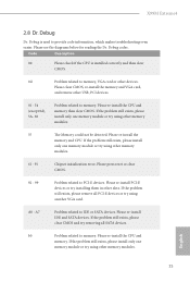
... Chipset initialization error. Please press reset or clear CMOS. 92 - 99 Problem related to memory. A7 Problem related to memory. If the problem still exists, please install only one memory module or try using another VGA card. Please clear CMOS, re-install the memory and VGA card, and remove other slots. If the problem still exists, please clear CMOS and try removing all PCI-E devices or try installing them in other USB, PCI devices. 01 - 54 (except 0d), 5A- 60 Problem related to IDE or SATA devices...
... Chipset initialization error. Please press reset or clear CMOS. 92 - 99 Problem related to memory. A7 Problem related to memory. If the problem still exists, please install only one memory module or try using another VGA card. Please clear CMOS, re-install the memory and VGA card, and remove other slots. If the problem still exists, please clear CMOS and try removing all PCI-E devices or try installing them in other USB, PCI devices. 01 - 54 (except 0d), 5A- 60 Problem related to IDE or SATA devices...

User Manual
Page 36
... identical PCI Express x16 graphics cards. Make sure that your power supply unit (PSU) can provide at least the minimum power your graphics card vendor for details.) English 30 Download the drivers from the AMD's website: www.amd.com 3. 2.10 CrossFireXTM and Quad CrossFireXTM Operation Guide his motherboard supports CrossFireXTM and Quad CrossFireXTM that allows you to install up to enable CrossFireXTM. Please refer to use identical CrossFireXTM-ready graphics cards...
... identical PCI Express x16 graphics cards. Make sure that your power supply unit (PSU) can provide at least the minimum power your graphics card vendor for details.) English 30 Download the drivers from the AMD's website: www.amd.com 3. 2.10 CrossFireXTM and Quad CrossFireXTM Operation Guide his motherboard supports CrossFireXTM and Quad CrossFireXTM that allows you to install up to enable CrossFireXTM. Please refer to use identical CrossFireXTM-ready graphics cards...
User Manual
Page 38
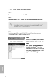
... select Enable AMD CrossFireX and click Apply. Select the GPU number according to installation. 2.10.2 Driver Installation and Setup Step 1 Power on your computer. he Catalyst Uninstaller is an optional download. English 32 We recommend using this utility to uninstall any VGA drivers installed in the Windows® system tray. Step 3 Install the required drivers and CATALYST Control Center then restart your computer and boot into OS. Step 2 Remove the AMD drivers...
... select Enable AMD CrossFireX and click Apply. Select the GPU number according to installation. 2.10.2 Driver Installation and Setup Step 1 Power on your computer. he Catalyst Uninstaller is an optional download. English 32 We recommend using this utility to uninstall any VGA drivers installed in the Windows® system tray. Step 3 Install the required drivers and CATALYST Control Center then restart your computer and boot into OS. Step 2 Remove the AMD drivers...
User Manual
Page 43
Utilities Menu he Support CD that comes with the motherboard contains necessary drivers and useful utilities that the motherboard supports. he drivers compatible to display the menu. Drivers Menu he CD automatically displays the Main Menu if "AUTORUN" is enabled in the Support CD to your system will be auto-detected and listed on the ile "ASRSETUP.EXE" in your CD-ROM drive. herefore, the drivers you install can work properly. To improve Windows 7 compatibility, please download and install the following hot...
Utilities Menu he Support CD that comes with the motherboard contains necessary drivers and useful utilities that the motherboard supports. he drivers compatible to display the menu. Drivers Menu he CD automatically displays the Main Menu if "AUTORUN" is enabled in the Support CD to your system will be auto-detected and listed on the ile "ASRSETUP.EXE" in your CD-ROM drive. herefore, the drivers you install can work properly. To improve Windows 7 compatibility, please download and install the following hot...

User Manual
Page 84
... start to enable onboard HD audio and automatically disable it when a sound card is selected, the power will remain of the Power and Keyboard LEDs when the system enters into Standby/Hibernation mode. If [Power Of] is installed. Onboard Debug Port LED Enable/disable the onboard Dr. Debug LED. 78 English Set to Auto to boot up when the power recovers. Good Night LED By enabling Good Night LED, the Power/HDD LEDs will also automatically switch of when the power recovers. Intel(R) Ethernet Connection...
... start to enable onboard HD audio and automatically disable it when a sound card is selected, the power will remain of the Power and Keyboard LEDs when the system enters into Standby/Hibernation mode. If [Power Of] is installed. Onboard Debug Port LED Enable/disable the onboard Dr. Debug LED. 78 English Set to Auto to boot up when the power recovers. Good Night LED By enabling Good Night LED, the Power/HDD LEDs will also automatically switch of when the power recovers. Intel(R) Ethernet Connection...

User Manual
Page 86
PS2 Y-Cable Enable the PS2 Y-Cable or set this option to Auto. 80 English Serial Port Address Select the address of the Serial port. 4.4.4 Super IO Coniguration Serial Port Enable or disable the Serial port.
PS2 Y-Cable Enable the PS2 Y-Cable or set this option to Auto. 80 English Serial Port Address Select the address of the Serial port. 4.4.4 Super IO Coniguration Serial Port Enable or disable the Serial port.

User Manual
Page 88
...encounter USB compatibility issues it is recommended to automatically enable the USB 3.0 driver ater entering the OS (USB 3.0 is enabled in BIOS). Set [Auto] to disable legacy USB support. Select UEFI Setup Only to use USB devices under Windows® 7). Set [Enabled] to keep the USB 3.0 driver enabled ater rebooting (USB 3.0 is disabled in BIOS). Intel USB 3.0 Mode Select Intel® USB 3.0 controller mode. Set [Disabled] to support USB devices under the UEFI setup and Windows/Linux operating systems only. 82 English Select UEFI Setup Only to disable the USB 3.0 ports...
...encounter USB compatibility issues it is recommended to automatically enable the USB 3.0 driver ater entering the OS (USB 3.0 is enabled in BIOS). Set [Auto] to disable legacy USB support. Select UEFI Setup Only to use USB devices under Windows® 7). Set [Enabled] to keep the USB 3.0 driver enabled ater rebooting (USB 3.0 is disabled in BIOS). Intel USB 3.0 Mode Select Intel® USB 3.0 controller mode. Set [Disabled] to support USB devices under the UEFI setup and Windows/Linux operating systems only. 82 English Select UEFI Setup Only to disable the USB 3.0 ports...
User Manual
Page 92
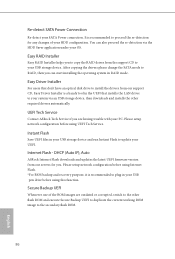
... via the HDD Saver application under your USB storage device. You can start installing the operating system in the UEFI that don't have an optical disk drive to install the drivers from our support CD, Easy Driver Installer is recommended to update your SATA Power connection. Please setup network coniguration before using UEFI Tech Service. Please setup network coniguration before using Internet Flash. *For BIOS backup and recovery purpose, it is a handy tool in RAID mode. Internet Flash - Re-detect SATA Power Connection Re-detect...
... via the HDD Saver application under your USB storage device. You can start installing the operating system in the UEFI that don't have an optical disk drive to install the drivers from our support CD, Easy Driver Installer is recommended to update your SATA Power connection. Please setup network coniguration before using UEFI Tech Service. Please setup network coniguration before using Internet Flash. *For BIOS backup and recovery purpose, it is a handy tool in RAID mode. Internet Flash - Re-detect SATA Power Connection Re-detect...

User Manual
Page 93
Save User Default Type a proile name and press enter to download the UEFI irmware. UEFI Download Server Select a server to save your settings as user default. Load User Default Load previously saved user defaults. 87 English Network Coniguration Use this to conigure internet connection settings for Internet Flash. X99M Extreme4 Internet Setting Enable or disable sound efects in the setup utility.
Save User Default Type a proile name and press enter to download the UEFI irmware. UEFI Download Server Select a server to save your settings as user default. Load User Default Load previously saved user defaults. 87 English Network Coniguration Use this to conigure internet connection settings for Internet Flash. X99M Extreme4 Internet Setting Enable or disable sound efects in the setup utility.

Quick Installation Guide
Page 4
...-pin DDR4 DIMM Slots (DDR4_D1, DDR4_C1) 4 CPU Fan Connector (CPU_FAN1) 5 CPU Fan Connector (CPU_FAN2) 6 TPM Header (TPMS1) 7 ATX Power Connector (ATXPWR1) 8 USB 3.0 Header (USB3_5_6) 9 Chassis Fan Connector (CHA_FAN2) 10 SATA3 Connectors (S_SATA3_0_1) 11 HDD Saver Connector (SATA_PWR_1) 12 SATA3 Connectors (S_SATA3_2_3) 13 SATA3 Connectors (SATA3_0_3) 14 SATA3 Connectors (SATA3_1_4) 15 SATA3 Connectors (SATA3_2_5) 16 Power LED Header (PLED1) 17 System Panel Header (PANEL1) 18 Clear CMOS Jumper (CLRCMOS1) 19 Chassis Speaker Header (SPEAKER1) 20 Chassis Fan Connector (CHA_FAN1) 21 USB 2.0 Header...
...-pin DDR4 DIMM Slots (DDR4_D1, DDR4_C1) 4 CPU Fan Connector (CPU_FAN1) 5 CPU Fan Connector (CPU_FAN2) 6 TPM Header (TPMS1) 7 ATX Power Connector (ATXPWR1) 8 USB 3.0 Header (USB3_5_6) 9 Chassis Fan Connector (CHA_FAN2) 10 SATA3 Connectors (S_SATA3_0_1) 11 HDD Saver Connector (SATA_PWR_1) 12 SATA3 Connectors (S_SATA3_2_3) 13 SATA3 Connectors (SATA3_0_3) 14 SATA3 Connectors (SATA3_1_4) 15 SATA3 Connectors (SATA3_2_5) 16 Power LED Header (PLED1) 17 System Panel Header (PANEL1) 18 Clear CMOS Jumper (CLRCMOS1) 19 Chassis Speaker Header (SPEAKER1) 20 Chassis Fan Connector (CHA_FAN1) 21 USB 2.0 Header...

Quick Installation Guide
Page 10
... PCI Express module up to Gen3 x4 (32 Gb/s) Connector • 1 x COM Port Header • 1 x TPM Header • 1 x Power LED Header • 2 x CPU Fan Connectors (1 x 4-pin, 1 x 3-pin) • 2 x Chassis Fan Connectors (1 x 4-pin, 1 x 3-pin) (Smart Fan Speed Control) • 1 x Power Fan Connector (3-pin) • 1 x 24 pin ATX Power Connector • 1 x 8 pin 12V Power Connector (Hi-Density Power Connector) • 1 x HDD Saver Connector • 1 x PCIe Power Connector • 1 x Front Panel Audio Connector • 1 x hunderbolt AIC Connector • 2 x USB 2.0 Headers (support...
... PCI Express module up to Gen3 x4 (32 Gb/s) Connector • 1 x COM Port Header • 1 x TPM Header • 1 x Power LED Header • 2 x CPU Fan Connectors (1 x 4-pin, 1 x 3-pin) • 2 x Chassis Fan Connectors (1 x 4-pin, 1 x 3-pin) (Smart Fan Speed Control) • 1 x Power Fan Connector (3-pin) • 1 x 24 pin ATX Power Connector • 1 x 8 pin 12V Power Connector (Hi-Density Power Connector) • 1 x HDD Saver Connector • 1 x PCIe Power Connector • 1 x Front Panel Audio Connector • 1 x hunderbolt AIC Connector • 2 x USB 2.0 Headers (support...

Quick Installation Guide
Page 24
... cable. Please connect the HDD Saver Cable to this connector to this connector when more than three graphics cards are installed. Please connect a hunderboltTM add-in card (AIC) to manage the power state of HDD. his motherboard provides an 8-pin ATX 12V power connector. To use a 20-pin ATX power supply, please plug it along Pin 1 and Pin 13. Please connect a 4 pin molex power cable to Pin 1-3. 12 24 1 13 8 5 4 1 GND +12V DETECT 1 his motherboard provides a 4-Pin CPU fan (Quiet Fan) connector. To use a 4-pin ATX power supply, please plug it along Pin 1 and Pin...
... cable. Please connect the HDD Saver Cable to this connector to this connector when more than three graphics cards are installed. Please connect a hunderboltTM add-in card (AIC) to manage the power state of HDD. his motherboard provides an 8-pin ATX 12V power connector. To use a 20-pin ATX power supply, please plug it along Pin 1 and Pin 13. Please connect a 4 pin molex power cable to Pin 1-3. 12 24 1 13 8 5 4 1 GND +12V DETECT 1 his motherboard provides a 4-Pin CPU fan (Quiet Fan) connector. To use a 4-pin ATX power supply, please plug it along Pin 1 and Pin...

Quick Installation Guide
Page 27
... VGA card, and remove other devices. Please re-install PCI-E devices or try using another VGA card. A7 Problem related to memory. If the problem still exists, please clear CMOS and try using other memory modules. Please re-install the CPU and memory. b0 Problem related to IDE or SATA devices. English 25 Please re-install the CPU and memory then clear CMOS. Please press reset or clear CMOS. 92 - 99 Problem related to PCI-E devices. Please see the diagrams below for reading the Dr. Debug codes...
... VGA card, and remove other devices. Please re-install PCI-E devices or try using another VGA card. A7 Problem related to memory. If the problem still exists, please clear CMOS and try using other memory modules. Please re-install the CPU and memory. b0 Problem related to IDE or SATA devices. English 25 Please re-install the CPU and memory then clear CMOS. Please press reset or clear CMOS. 92 - 99 Problem related to PCI-E devices. Please see the diagrams below for reading the Dr. Debug codes...


