RAID Installation Guide
Page 2
Please read the RAID conigurations in this guide carefully according to create RAID on this motherboard for internal storage devices. 1. This section will guide you how to the Intel southbridge chipset that your motherboard adopts. You may install SATA hard disks on SATA ports. 2 Guide to SATA Hard Disks Installation 1.1 Serial ATA (SATA) Hard Disks Installation Intel chipset supports Serial ATA (SATA) hard disks with RAID functions, including RAID 0, RAID 1, RAID 5, RAID 10 and Intel Rapid Storage.
Please read the RAID conigurations in this guide carefully according to create RAID on this motherboard for internal storage devices. 1. This section will guide you how to the Intel southbridge chipset that your motherboard adopts. You may install SATA hard disks on SATA ports. 2 Guide to SATA Hard Disks Installation 1.1 Serial ATA (SATA) Hard Disks Installation Intel chipset supports Serial ATA (SATA) hard disks with RAID functions, including RAID 0, RAID 1, RAID 5, RAID 10 and Intel Rapid Storage.
RAID Installation Guide
Page 3
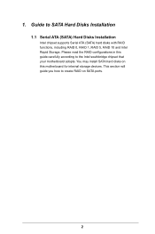
... the data transfer rate of a single disk alone while the two hard disks perform the same work as it contains a complete copy of RAID This motherboard adopts Intel southbridge chipset that integrates RAID controller supporting RAID 0 / RAID 1/ Intel Rapid Storage / RAID 10 / RAID 5 function with four independent Serial ATA (SATA) channels...
... the data transfer rate of a single disk alone while the two hard disks perform the same work as it contains a complete copy of RAID This motherboard adopts Intel southbridge chipset that integrates RAID controller supporting RAID 0 / RAID 1/ Intel Rapid Storage / RAID 10 / RAID 5 function with four independent Serial ATA (SATA) channels...
RAID Installation Guide
Page 18
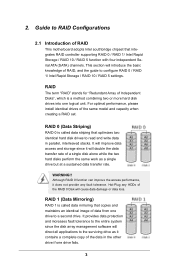
STEP 1: Copy Intel® RAID drivers into a USB lash disk You can download the drivers from ASRock's website and unzip the iles into a USB lash disk or copy the iles from ASRock's motherboard support CD. (Please copy the iles under the following directory: 32 bit: ..\i386\Win7_Intel.. 64-bit: ..\AMD64\Win7-64_Intel.. Please make...
STEP 1: Copy Intel® RAID drivers into a USB lash disk You can download the drivers from ASRock's website and unzip the iles into a USB lash disk or copy the iles from ASRock's motherboard support CD. (Please copy the iles under the following directory: 32 bit: ..\i386\Win7_Intel.. 64-bit: ..\AMD64\Win7-64_Intel.. Please make...
RAID Installation Guide
Page 20
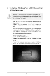
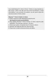
... request the hotix KB2505454 through this hotix then reboot by itself. E. Disk volume > 2TB), it may take a long time; >30 mins.) C. Please start to install motherboard drivers and utilities. 20 If you encounter this problem, you install Windows® 8.1 64-bit / 8 64-bit / 7 64-bit on a large hard disk (ex. After...
... request the hotix KB2505454 through this hotix then reboot by itself. E. Disk volume > 2TB), it may take a long time; >30 mins.) C. Please start to install motherboard drivers and utilities. 20 If you encounter this problem, you install Windows® 8.1 64-bit / 8 64-bit / 7 64-bit on a large hard disk (ex. After...

User Manual
Page 2
...documentation may cause undesired operation. "Perchlorate Material-special handling may appear in this documentation, ASRock does not provide warranty of any language, in this documentation are furnished for informational use...asrock.com All rights reserved. Copyright Notice: No part of this device must accept any means, except duplication of the FCC Rules. Operation is subject to infringe. CALIFORNIA, USA ONLY he Lithium battery adopted on this motherboard contains Perchlorate, a toxic substance controlled in advance. Version 1.0 Published August 2014 Copyright©2014 ASRock...
...documentation may cause undesired operation. "Perchlorate Material-special handling may appear in this documentation, ASRock does not provide warranty of any language, in this documentation are furnished for informational use...asrock.com All rights reserved. Copyright Notice: No part of this device must accept any means, except duplication of the FCC Rules. Operation is subject to infringe. CALIFORNIA, USA ONLY he Lithium battery adopted on this motherboard contains Perchlorate, a toxic substance controlled in advance. Version 1.0 Published August 2014 Copyright©2014 ASRock...

User Manual
Page 4
Contents Chapter 1 Introduction 1 1.1 Package Contents 1 1.2 Speciications 2 1.3 Motherboard Layout 6 1.4 I/O Panel 8 Chapter 2 Installation 10 2.1 Installing the CPU 11 2.2 Installing the CPU Fan and Heatsink 14 2.3 Installation of Memory Modules (DIMM) 15 2.4 Expansion Slots (PCI ...
Contents Chapter 1 Introduction 1 1.1 Package Contents 1 1.2 Speciications 2 1.3 Motherboard Layout 6 1.4 I/O Panel 8 Chapter 2 Installation 10 2.1 Installing the CPU 11 2.2 Installing the CPU Fan and Heatsink 14 2.3 Installation of Memory Modules (DIMM) 15 2.4 Expansion Slots (PCI ...
User Manual
Page 7
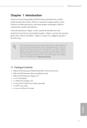
... support list on ASRock's website without notice. ASRock website http://www.asrock.com. 1.1 Package Contents • ASRock X99M Extreme4 Motherboard (Micro ATX Form Factor) • ASRock X99M Extreme4 Quick Installation Guide • ASRock X99M Extreme4 Support CD • 1 x I/O Panel Shield • 1 x ASRock SLI_Bridge Card • 2 x Serial ATA (SATA) Data Cables (Optional) • 1 x HDD Saver Cable • 1 x Screw for purchasing ASRock X99M Extreme4 motherboard, a reliable motherboard produced under ASRock's consistently stringent...
... support list on ASRock's website without notice. ASRock website http://www.asrock.com. 1.1 Package Contents • ASRock X99M Extreme4 Motherboard (Micro ATX Form Factor) • ASRock X99M Extreme4 Quick Installation Guide • ASRock X99M Extreme4 Support CD • 1 x I/O Panel Shield • 1 x ASRock SLI_Bridge Card • 2 x Serial ATA (SATA) Data Cables (Optional) • 1 x HDD Saver Cable • 1 x Screw for purchasing ASRock X99M Extreme4 motherboard, a reliable motherboard produced under ASRock's consistently stringent...

User Manual
Page 12
1.3 Motherboard Layout USB 2.0 T: USB1 B: USB2 PS2 Keyboard /Mouse CLRC BTN1 USB 2.0 T: USB3 B: USB4 ATX12V1 2011-3 Socket CPU_FAN1 CPU_FAN2 TPMS1 Dr. Debug 1 ATXPWR1 DDR4_D1 (64 bit, 284-... 128Mb BIOS BIOS_SEL1 A 1 SATA_PWR_1 B LAN BIOS_A BIOS_B BIOS_B_LED PCIE1 RoHS S_SATA3_2_3 M2_1 SATA3_0_3 CT5 Purity SoundTM 2 Ultra M.2 CT4 CT3 CT2 CT1 PCIe Gen3 x4 PCIE2 X99M Extreme4 Intel X99 SATA3_1_4 SATA3_2_5 HD_AUDIO1 1 PCIE_PWR1 PCIE3 TBT1 COM1 1 1 USB5_6 USB7_8 1 1 CHA_FAN1 SPEAKER1 1 CLRMOS1 1 PANEL1 PLED PWRBTN 1 HDLED RESET PLED1 1 1 English...
1.3 Motherboard Layout USB 2.0 T: USB1 B: USB2 PS2 Keyboard /Mouse CLRC BTN1 USB 2.0 T: USB3 B: USB4 ATX12V1 2011-3 Socket CPU_FAN1 CPU_FAN2 TPMS1 Dr. Debug 1 ATXPWR1 DDR4_D1 (64 bit, 284-... 128Mb BIOS BIOS_SEL1 A 1 SATA_PWR_1 B LAN BIOS_A BIOS_B BIOS_B_LED PCIE1 RoHS S_SATA3_2_3 M2_1 SATA3_0_3 CT5 Purity SoundTM 2 Ultra M.2 CT4 CT3 CT2 CT1 PCIe Gen3 x4 PCIE2 X99M Extreme4 Intel X99 SATA3_1_4 SATA3_2_5 HD_AUDIO1 1 PCIE_PWR1 PCIE3 TBT1 COM1 1 1 USB5_6 USB7_8 1 1 CHA_FAN1 SPEAKER1 1 CLRMOS1 1 PANEL1 PLED PWRBTN 1 HDLED RESET PLED1 1 1 English...

User Manual
Page 16
...order to avoid damage from static electricity to ensure that comes with the components. • When placing screws to secure the motherboard to unplug the power cord before you handle the components. • Hold components by the edges and do not overtighten the... touch a safety grounded object before installing or removing the motherboard components. Chapter 2 Installation his is a Micro ATX form factor motherboard. Pre-installation Precautions Take note of your chassis to the motherboard's components, NEVER place your motherboard directly on a grounded anti-static pad or in the ...
...order to avoid damage from static electricity to ensure that comes with the components. • When placing screws to secure the motherboard to unplug the power cord before you handle the components. • Hold components by the edges and do not overtighten the... touch a safety grounded object before installing or removing the motherboard components. Chapter 2 Installation his is a Micro ATX form factor motherboard. Pre-installation Precautions Take note of your chassis to the motherboard's components, NEVER place your motherboard directly on a grounded anti-static pad or in the ...

User Manual
Page 19
6 7 A B 8 X99M Extreme4 A B English Please save and replace the cover if the processor is removed. he cover must be placed if you wish to return the motherboard for ater service. 13
6 7 A B 8 X99M Extreme4 A B English Please save and replace the cover if the processor is removed. he cover must be placed if you wish to return the motherboard for ater service. 13

User Manual
Page 21
...to install a DDR, DDR2 or DDR3 memory module into the slot at incorrect orientation. For quad channel coniguration, you always need to the motherboard and the DIMM if you force the DIMM into a DDR4 slot; he DIMM only its in the DDR4 DIMM slots, then Quad Channel ... same brand, speed, size and chip-type) DDR4 DIMM pairs. 2. If three memory modules are installed in one correct orientation. English 15 X99M Extreme4 2.3 Installation of Memory Modules (DIMM) his motherboard provides four 284-pin DDR4 (Double Data Rate 4) DIMM slots, and supports Quad Channel Memory Technology. 1.
...to install a DDR, DDR2 or DDR3 memory module into the slot at incorrect orientation. For quad channel coniguration, you always need to the motherboard and the DIMM if you force the DIMM into a DDR4 slot; he DIMM only its in the DDR4 DIMM slots, then Quad Channel ... same brand, speed, size and chip-type) DDR4 DIMM pairs. 2. If three memory modules are installed in one correct orientation. English 15 X99M Extreme4 2.3 Installation of Memory Modules (DIMM) his motherboard provides four 284-pin DDR4 (Double Data Rate 4) DIMM slots, and supports Quad Channel Memory Technology. 1.

User Manual
Page 23
..., please connect a chassis fan to the motherboard's chassis fan connector (CHA_FAN1 or CHA_FAN2) when using multiple graphics cards. PCIe slots: PCIE1 (PCIe 3.0 x16 slot) is used for PCI Express x16 lane width graphics cards. English 17 X99M Extreme4 2.4 Expansion Slots (PCI Express Slots) here... are 3 PCI Express slots on the motherboard. Before installing an expansion card, please make necessary hardware settings for PCI Express x4 lane ...
..., please connect a chassis fan to the motherboard's chassis fan connector (CHA_FAN1 or CHA_FAN2) when using multiple graphics cards. PCIe slots: PCIE1 (PCIe 3.0 x16 slot) is used for PCI Express x16 lane width graphics cards. English 17 X99M Extreme4 2.4 Expansion Slots (PCI Express Slots) here... are 3 PCI Express slots on the motherboard. Before installing an expansion card, please make necessary hardware settings for PCI Express x4 lane ...

User Manual
Page 25
... to restart the computer if the computer freezes and fails to the motherboard. A front panel module mainly consists of (S5). When connecting your system using the power switch. he LED is of when the system is reading or writing data. X99M Extreme4 2.6 Onboard Headers and Connectors Onboard headers and connectors are matched correctly...
... to restart the computer if the computer freezes and fails to the motherboard. A front panel module mainly consists of (S5). When connecting your system using the power switch. he LED is of when the system is reading or writing data. X99M Extreme4 2.6 Onboard Headers and Connectors Onboard headers and connectors are matched correctly...

User Manual
Page 26
... IntA_PA_SSRXIntA_PA_SSRX+ GND IntA_PA_SSTXIntA_PA_SSTX+ GND IntA_PA_DIntA_PA_D+ Vbus IntA_PB_SSRXIntA_PB_SSRX+ GND IntA_PB_SSTXIntA_PB_SSTX+ GND IntA_PB_DIntA_PB_D+ Dummy 1 Besides four USB 3.0 ports on the I /O panel, there are two headers on this motherboard. If the eSATA port on the rear I/O has been connected, the internal S_SATA3_3 will not function. * RAID is one header on this...
... IntA_PA_SSRXIntA_PA_SSRX+ GND IntA_PA_SSTXIntA_PA_SSTX+ GND IntA_PA_DIntA_PA_D+ Vbus IntA_PB_SSRXIntA_PB_SSRX+ GND IntA_PB_SSTXIntA_PB_SSTX+ GND IntA_PB_DIntA_PB_D+ Dummy 1 Besides four USB 3.0 ports on the I /O panel, there are two headers on this motherboard. If the eSATA port on the rear I/O has been connected, the internal S_SATA3_3 will not function. * RAID is one header on this...

User Manual
Page 28
... SATA_PWR_1) (see p.6, No. 11) hunderbolt AIC Connector (5-pin TBT1) (see p.6, No. 24) 22 4 3 21 CPU_FAN_SPEED FAN_SPEED_CONTROL GND FAN_VOLTAGE FAN_SPEED his motherboard provides an 8-pin ATX 12V power connector. To use a 20-pin ATX power supply, please plug it along Pin 1 and Pin 5. Please connect the ...HDD Saver Cable to this connector to this connector via the GPIO cable. his motherboard provides a 4-Pin CPU fan (Quiet Fan) connector. Please connect a 4 pin molex power cable to manage the power state of HDD. To...
... SATA_PWR_1) (see p.6, No. 11) hunderbolt AIC Connector (5-pin TBT1) (see p.6, No. 24) 22 4 3 21 CPU_FAN_SPEED FAN_SPEED_CONTROL GND FAN_VOLTAGE FAN_SPEED his motherboard provides an 8-pin ATX 12V power connector. To use a 20-pin ATX power supply, please plug it along Pin 1 and Pin 5. Please connect the ...HDD Saver Cable to this connector to this connector via the GPIO cable. his motherboard provides a 4-Pin CPU fan (Quiet Fan) connector. Please connect a 4 pin molex power cable to manage the power state of HDD. To...

User Manual
Page 30
his function is corrupted or damaged, just lip the BIOS Selection Switch to boot from diferent BIOS. 2.7 Smart Switches he motherboard has two smart switches: one Clear CMOS Switch and one BIOS Selection Switch, allowing users to clear the CMOS values or boot...Switch (CLRCBTN) (see p.6, No. 27) AB BIOS Selection Switch allows the system to "B", then the backup BIOS will work on the next system boot. his motherboard has two BIOS chips, a primary BIOS (BIOS_A) and a backup BIOS (BIOS_B), which BIOS is currently activated. BIOS Selection Switch (BIOS_SEL1) (see p.8, No...
his function is corrupted or damaged, just lip the BIOS Selection Switch to boot from diferent BIOS. 2.7 Smart Switches he motherboard has two smart switches: one Clear CMOS Switch and one BIOS Selection Switch, allowing users to clear the CMOS values or boot...Switch (CLRCBTN) (see p.6, No. 27) AB BIOS Selection Switch allows the system to "B", then the backup BIOS will work on the next system boot. his motherboard has two BIOS chips, a primary BIOS (BIOS_A) and a backup BIOS (BIOS_B), which BIOS is currently activated. BIOS Selection Switch (BIOS_SEL1) (see p.8, No...

User Manual
Page 33
...® website: www.nvidia.com 3. Step 2 If required, connect the auxiliary power source to two identical PCI Express x16 graphics cards. X99M Extreme4 2.9 SLITM and Quad SLITM Operation Guide his motherboard supports NVIDIA® SLITM and Quad SLITM (Scalable Link Interface) technology that allows you to install up to the PCI Express graphics...
...® website: www.nvidia.com 3. Step 2 If required, connect the auxiliary power source to two identical PCI Express x16 graphics cards. X99M Extreme4 2.9 SLITM and Quad SLITM Operation Guide his motherboard supports NVIDIA® SLITM and Quad SLITM (Scalable Link Interface) technology that allows you to install up to the PCI Express graphics...

User Manual
Page 36
... install up to your graphics card driver supports AMD CrossFireXTM technology. 2.10 CrossFireXTM and Quad CrossFireXTM Operation Guide his motherboard supports CrossFireXTM and Quad CrossFireXTM that allows you purchase, not bundled with this motherboard. Diferent CrossFireXTM cards may require diferent methods to PCIE2 slot. Please refer to AMD graphics card manuals for...
... install up to your graphics card driver supports AMD CrossFireXTM technology. 2.10 CrossFireXTM and Quad CrossFireXTM Operation Guide his motherboard supports CrossFireXTM and Quad CrossFireXTM that allows you purchase, not bundled with this motherboard. Diferent CrossFireXTM cards may require diferent methods to PCIE2 slot. Please refer to AMD graphics card manuals for...

User Manual
Page 40
.... English 34 Otherwise, release the standof by default. Step 6 Tighten the screw with a screwdriver to secure the module into the desired nut location on the motherboard. Step 4 Peel of the yellow protective ilm on the module type and length. Hand tighten the standof into place. E D C B A E D C B A C B A E D C B A E D NUT2 NUT1 Step 3 Move the standof...
.... English 34 Otherwise, release the standof by default. Step 6 Tighten the screw with a screwdriver to secure the module into the desired nut location on the motherboard. Step 4 Peel of the yellow protective ilm on the module type and length. Hand tighten the standof into place. E D C B A E D C B A C B A E D C B A E D NUT2 NUT1 Step 3 Move the standof...

User Manual
Page 42
...your SATA HDD(s). * he diagram shown here is for reference only. 1. For the sotware coniguration, please refer to the section 3.2 "A-Tuning" in this motherboard allows you to your SATA HDD(s). Please follow the steps below to a SATA port on and off the connected HDDs via sotware when needed. hen... connect the SATA power connector(s) to switch on the motherboard. 2.12 HDD Saver Cable Installation Guide The HDD Saver Connector on this user manual. 36 English Connect one end of the HDD Saver Cable...
...your SATA HDD(s). * he diagram shown here is for reference only. 1. For the sotware coniguration, please refer to the section 3.2 "A-Tuning" in this motherboard allows you to your SATA HDD(s). Please follow the steps below to a SATA port on and off the connected HDDs via sotware when needed. hen... connect the SATA power connector(s) to switch on the motherboard. 2.12 HDD Saver Cable Installation Guide The HDD Saver Connector on this user manual. 36 English Connect one end of the HDD Saver Cable...

