
User Manual
Page 27
...High Deinition Audio supports Jack Sensing, but the panel wire on the chassis must support HDA to the "FrontMic" Tab in our manual and chassis manual to OUT2_L. E. Connect Mic_IN (MIC) to the ground pin. FAN_SPEED_CONTROL FAN_SPEED +12V GND 1 234 GND FAN_VOLTAGE FAN_SPEED Please connect...) to OUT2_R and Audio_L (LIN) to install your system. 2. Please follow the instructions in the Realtek Control panel and adjust "Recording Volume". X99M Extreme4 Front Panel Audio Header (9-pin HD_AUDIO1) (see p.6, No. 28) DUMMY SPEAKER 1 +5V DUMMY Please connect the chassis speaker to the front ...
...High Deinition Audio supports Jack Sensing, but the panel wire on the chassis must support HDA to the "FrontMic" Tab in our manual and chassis manual to OUT2_L. E. Connect Mic_IN (MIC) to the ground pin. FAN_SPEED_CONTROL FAN_SPEED +12V GND 1 234 GND FAN_VOLTAGE FAN_SPEED Please connect...) to OUT2_R and Audio_L (LIN) to install your system. 2. Please follow the instructions in the Realtek Control panel and adjust "Recording Volume". X99M Extreme4 Front Panel Audio Header (9-pin HD_AUDIO1) (see p.6, No. 28) DUMMY SPEAKER 1 +5V DUMMY Please connect the chassis speaker to the front ...

User Manual
Page 30
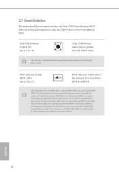
... power of your computer and unplug the power supply. Users may refer to the BIOS LEDs (BIOS_A_LED or BIOS_ B_LED) to update the backup BIOS manually. BIOS Selection Switch (BIOS_SEL1) (see p.8, No. 14) Clear CMOS Switch allows users to clear the CMOS values or boot from either BIOS A or BIOS B. his...
... power of your computer and unplug the power supply. Users may refer to the BIOS LEDs (BIOS_A_LED or BIOS_ B_LED) to update the backup BIOS manually. BIOS Selection Switch (BIOS_SEL1) (see p.8, No. 14) Clear CMOS Switch allows users to clear the CMOS values or boot from either BIOS A or BIOS B. his...

User Manual
Page 36
... guide. 2.10.1 Installing Two CrossFireXTM-Ready Graphics Cards Step 1 Insert one graphics card into PCIE1 slot and the other graphics card to AMD graphics card manuals for details. 4. Currently CrossFireXTM and Quad CrossFireXTM are supported with this motherboard. CrossFire Bridge Step 2 Connect two graphics cards by installing a CrossFire Bridge on the...
... guide. 2.10.1 Installing Two CrossFireXTM-Ready Graphics Cards Step 1 Insert one graphics card into PCIE1 slot and the other graphics card to AMD graphics card manuals for details. 4. Currently CrossFireXTM and Quad CrossFireXTM are supported with this motherboard. CrossFire Bridge Step 2 Connect two graphics cards by installing a CrossFire Bridge on the...

User Manual
Page 42
... to the HDD Saver Connector (SATA_ PWR_1) placed near the SATA ports. 2.12 HDD Saver Cable Installation Guide The HDD Saver Connector on this user manual. 36 English
... to the HDD Saver Connector (SATA_ PWR_1) placed near the SATA ports. 2.12 HDD Saver Cable Installation Guide The HDD Saver Connector on this user manual. 36 English

User Manual
Page 56
... icon back to use Orbweb.ME Professional. 50 English Step 4 Click on how to online. Step 3 Click the Connect icon . Please refer to the user manual of your host computer from a client device. You have to physically wake up computer in with your Orbweb.ME account and password. If the Remote...
... icon back to use Orbweb.ME Professional. 50 English Step 4 Click on how to online. Step 3 Click the Connect icon . Please refer to the user manual of your host computer from a client device. You have to physically wake up computer in with your Orbweb.ME account and password. If the Remote...

User Manual
Page 58
... and password. Using Xplorer Xplorer allows you to remotely access documents on Xplorer. For more instructions on how to use Xplorer, refer to the user manual of the Orbweb.ME Professional. 52 English
... and password. Using Xplorer Xplorer allows you to remotely access documents on Xplorer. For more instructions on how to use Xplorer, refer to the user manual of the Orbweb.ME Professional. 52 English

User Manual
Page 59
... section and you can also delete, rename, move, and copy a selected ile. Tap a ile name to the user manual of the Orbweb.ME Professional. Tutorial Video 53 English Step 3 Tap the Connect icon . X99M Extreme4 For iOS or Android Mobile Devices users: Download and install "Orbweb.ME Professional" app from the App Store...
... section and you can also delete, rename, move, and copy a selected ile. Tap a ile name to the user manual of the Orbweb.ME Professional. Tutorial Video 53 English Step 3 Tap the Connect icon . X99M Extreme4 For iOS or Android Mobile Devices users: Download and install "Orbweb.ME Professional" app from the App Store...

User Manual
Page 77
... from diferent DIMM separation parameter. tWWDD Conigure Write to Write diferent DIMM dead cycle Back to back READ to WRITE from diferent rank separation parameter. X99M Extreme4 tRWDR Conigure Read to Write diferent rank dead cycle Back to back READ to WRITE from diferent DIMM separation parameter. ODT WR (CH A) Conigure the... on die termination resistors' WR for channel A. tWRDD Conigure Write to Read diferent DIMM dead cycle Back to back READ to change ODT (CH A) Auto/Manual settings.
... from diferent DIMM separation parameter. tWWDD Conigure Write to Write diferent DIMM dead cycle Back to back READ to WRITE from diferent rank separation parameter. X99M Extreme4 tRWDR Conigure Read to Write diferent rank dead cycle Back to back READ to WRITE from diferent DIMM separation parameter. ODT WR (CH A) Conigure the... on die termination resistors' WR for channel A. tWRDD Conigure Write to Read diferent DIMM dead cycle Back to back READ to change ODT (CH A) Auto/Manual settings.

User Manual
Page 78
...ODT PARK (CH C) Conigure the memory on die termination resistors' WR for channel C. ODT NOM (CH C) Use this to change ODT (CH D) Auto/Manual settings. ODT WR (CH D) Conigure the memory on die termination resistors' PARK for channel D. Override: he voltage is [Auto]. ODT NOM (CH D) Use... this to change ODT (CH C) Auto/Manual settings. ODT WR (CH C) Conigure the memory on die termination resistors' WR for the CPU Cache. ODT NOM (CH B) Use this to change ODT...
...ODT PARK (CH C) Conigure the memory on die termination resistors' WR for channel C. ODT NOM (CH C) Use this to change ODT (CH D) Auto/Manual settings. ODT WR (CH D) Conigure the memory on die termination resistors' PARK for channel D. Override: he voltage is [Auto]. ODT NOM (CH D) Use... this to change ODT (CH C) Auto/Manual settings. ODT WR (CH C) Conigure the memory on die termination resistors' WR for the CPU Cache. ODT NOM (CH B) Use this to change ODT...

Quick Installation Guide
Page 23
C. To activate the front mic, go to Ground (GND). Connect Ground (GND) to the "FrontMic" Tab in our manual and chassis manual to OUT2_L. You don't need to this header. Chassis Speaker Header (4-pin SPEAKER1) (see p.1, No. 19) Chassis and Power Fan Connectors (4-... Realtek Control panel and adjust "Recording Volume". Connect Audio_R (RIN) to OUT2_R and Audio_L (LIN) to install your system. 2. English 21 D. E. X99M Extreme4 Front Panel Audio Header (9-pin HD_AUDIO1) (see p.1, No. 28) DUMMY SPEAKER 1 +5V DUMMY Please connect the chassis speaker to connect them for the...
C. To activate the front mic, go to Ground (GND). Connect Ground (GND) to the "FrontMic" Tab in our manual and chassis manual to OUT2_L. You don't need to this header. Chassis Speaker Header (4-pin SPEAKER1) (see p.1, No. 19) Chassis and Power Fan Connectors (4-... Realtek Control panel and adjust "Recording Volume". Connect Audio_R (RIN) to OUT2_R and Audio_L (LIN) to install your system. 2. English 21 D. E. X99M Extreme4 Front Panel Audio Header (9-pin HD_AUDIO1) (see p.1, No. 28) DUMMY SPEAKER 1 +5V DUMMY Please connect the chassis speaker to connect them for the...
Quick Installation Guide
Page 26
... backup BIOS will work on the next system boot. Ater that, use "Secure Backup UEFI" in the UEFI Setup Utility to update the backup BIOS manually. English 24
... backup BIOS will work on the next system boot. Ater that, use "Secure Backup UEFI" in the UEFI Setup Utility to update the backup BIOS manually. English 24

Quick Installation Guide
Page 32
... only. 1. Connect one end of the SATA data cable to two SATA HDDs. 2. hen connect the other end to the section 3.2 "A-Tuning" in the user manual. 30 English hen connect the SATA power connector(s) to the HDD Saver Connector (SATA_ PWR_1) placed near the SATA ports. Please follow the steps below...
... only. 1. Connect one end of the SATA data cable to two SATA HDDs. 2. hen connect the other end to the section 3.2 "A-Tuning" in the user manual. 30 English hen connect the SATA power connector(s) to the HDD Saver Connector (SATA_ PWR_1) placed near the SATA ports. Please follow the steps below...
