RAID Installation Guide
Page 7
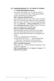
... your USB storage device with RAID functions, please follow the procedures below. STEP 1: Setting the BIOS RAID Items After installing the hard disk drives, please set the option SATA Mode Selection to [RAID]. Boot your system, and press key to your SATA / SATA2 / SATA3 HDDs with just one simple click in UEFI setup. 2.3 Installing Windows® 8.1 / 8.1 64-bit / 8 / 8 64-bit / 7 / 7 64-bit With RAID Functions If you exit BIOS setup. STEP 2: Use ASRock Easy RAID Installer Easy RAID Installer can copy the RAID driver from a support CD to enter BIOS setup utility. Please...
... your USB storage device with RAID functions, please follow the procedures below. STEP 1: Setting the BIOS RAID Items After installing the hard disk drives, please set the option SATA Mode Selection to [RAID]. Boot your system, and press key to your SATA / SATA2 / SATA3 HDDs with just one simple click in UEFI setup. 2.3 Installing Windows® 8.1 / 8.1 64-bit / 8 / 8 64-bit / 7 / 7 64-bit With RAID Functions If you exit BIOS setup. STEP 2: Use ASRock Easy RAID Installer Easy RAID Installer can copy the RAID driver from a support CD to enter BIOS setup utility. Please...
RAID Installation Guide
Page 18
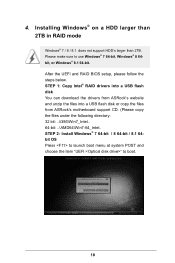
... a USB lash disk or copy the iles from ASRock's motherboard support CD. (Please copy the iles under the following directory: 32 bit: ..\i386\Win7_Intel.. 64-bit: ..\AMD64\Win7-64_Intel.. Installing Windows® on a HDD larger than 2TB in RAID mode Windows® 7 / 8 / 8.1 does not support HDD's larger than 2TB. STEP 2: Install Windows® 7 64-bit / 8 64-bit / 8.1 64bit OS Press to launch boot menu at system POST and choose the item "UEFI:" to use Windows...
... a USB lash disk or copy the iles from ASRock's motherboard support CD. (Please copy the iles under the following directory: 32 bit: ..\i386\Win7_Intel.. 64-bit: ..\AMD64\Win7-64_Intel.. Installing Windows® on a HDD larger than 2TB in RAID mode Windows® 7 / 8 / 8.1 does not support HDD's larger than 2TB. STEP 2: Install Windows® 7 64-bit / 8 64-bit / 8.1 64bit OS Press to launch boot menu at system POST and choose the item "UEFI:" to use Windows...
RAID Installation Guide
Page 20
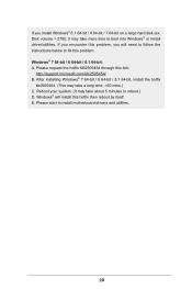
...-bit / 7 64-bit on a large hard disk (ex. After installing Windows® 7 64-bit / 8 64-bit / 8.1 64-bit, install the hotix kb2505454. (This may take about 5 minutes to ix this problem. If you will install this link: http://support.microsoft.com/kb/2505454/ B. Windows® 7 64-bit / 8 64-bit / 8.1 64-bit: A. Reboot your system. (It may take more time to install motherboard drivers and utilities. 20 Please start to boot into Windows® or install driver/utilities...
...-bit / 7 64-bit on a large hard disk (ex. After installing Windows® 7 64-bit / 8 64-bit / 8.1 64-bit, install the hotix kb2505454. (This may take about 5 minutes to ix this problem. If you will install this link: http://support.microsoft.com/kb/2505454/ B. Windows® 7 64-bit / 8 64-bit / 8.1 64-bit: A. Reboot your system. (It may take more time to install motherboard drivers and utilities. 20 Please start to boot into Windows® or install driver/utilities...

User Manual
Page 4
... Package Contents 1 1.2 Speciications 2 1.3 Motherboard Layout 6 1.4 I/O Panel 8 Chapter 2 Installation 10 2.1 Installing the CPU 11 2.2 Installing the CPU Fan and Heatsink 14 2.3 Installation of Memory Modules (DIMM) 15 2.4 Expansion Slots (PCI Express Slots) 17 2.5 Jumpers Setup 19 2.6 Onboard Headers and Connectors 21 2.7 Smart Switches 26 2.8 SLITM , 3-Way SLITMand Quad SLITM Operation Guide 27 2.8.1 Installing Two SLITM-Ready Graphics Cards 27 2.8.2 Installing Three SLITM-Ready Graphics Cards 29 2.8.3 Driver Installation and Setup 31 2.9 CrossFireXTM, 3-Way...
... Package Contents 1 1.2 Speciications 2 1.3 Motherboard Layout 6 1.4 I/O Panel 8 Chapter 2 Installation 10 2.1 Installing the CPU 11 2.2 Installing the CPU Fan and Heatsink 14 2.3 Installation of Memory Modules (DIMM) 15 2.4 Expansion Slots (PCI Express Slots) 17 2.5 Jumpers Setup 19 2.6 Onboard Headers and Connectors 21 2.7 Smart Switches 26 2.8 SLITM , 3-Way SLITMand Quad SLITM Operation Guide 27 2.8.1 Installing Two SLITM-Ready Graphics Cards 27 2.8.2 Installing Three SLITM-Ready Graphics Cards 29 2.8.3 Driver Installation and Setup 31 2.9 CrossFireXTM, 3-Way...

User Manual
Page 7
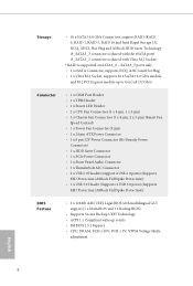
... Contents • ASRock X99 Extreme4 Motherboard (ATX Form Factor) • ASRock X99 Extreme4 Quick Installation Guide • ASRock X99 Extreme4 Support CD • 1 x I/O Panel Shield • 1 x ASRock SLI_Bridge_2S Card • 1 x ASRock 3-Way SLI-2S1S Bridge Card • 4 x Serial ATA (SATA) Data Cables (Optional) • 1 x HDD Saver Cable • 1 x Screw for purchasing ASRock X99 Extreme4 motherboard, a reliable motherboard produced under ASRock's consistently stringent quality control. Because the motherboard speciications and the BIOS sotware might be updated, the content...
... Contents • ASRock X99 Extreme4 Motherboard (ATX Form Factor) • ASRock X99 Extreme4 Quick Installation Guide • ASRock X99 Extreme4 Support CD • 1 x I/O Panel Shield • 1 x ASRock SLI_Bridge_2S Card • 1 x ASRock 3-Way SLI-2S1S Bridge Card • 4 x Serial ATA (SATA) Data Cables (Optional) • 1 x HDD Saver Cable • 1 x Screw for purchasing ASRock X99 Extreme4 motherboard, a reliable motherboard produced under ASRock's consistently stringent quality control. Because the motherboard speciications and the BIOS sotware might be updated, the content...

User Manual
Page 10
... PCI Express module up to Gen3 x4 (32 Gb/s) Connector • 1 x COM Port Header • 1 x TPM Header • 1 x Power LED Header • 2 x CPU Fan Connectors (1 x 4-pin, 1 x 3-pin) • 3 x Chassis Fan Connectors (1 x 4-pin, 2 x 3-pin) (Smart Fan Speed Control) • 1 x Power Fan Connector (3-pin) • 1 x 24 pin ATX Power Connector • 1 x 8 pin 12V Power Connector (Hi-Density Power Connector) • 1 x HDD Saver Connector • 1 x PCIe Power Connector • 1 x Front Panel Audio Connector • 1 x hunderbolt AIC Connector • 2 x USB 2.0 Headers (support...
... PCI Express module up to Gen3 x4 (32 Gb/s) Connector • 1 x COM Port Header • 1 x TPM Header • 1 x Power LED Header • 2 x CPU Fan Connectors (1 x 4-pin, 1 x 3-pin) • 3 x Chassis Fan Connectors (1 x 4-pin, 2 x 3-pin) (Smart Fan Speed Control) • 1 x Power Fan Connector (3-pin) • 1 x 24 pin ATX Power Connector • 1 x 8 pin 12V Power Connector (Hi-Density Power Connector) • 1 x HDD Saver Connector • 1 x PCIe Power Connector • 1 x Front Panel Audio Connector • 1 x hunderbolt AIC Connector • 2 x USB 2.0 Headers (support...
User Manual
Page 13
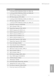
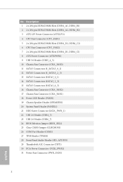
... (SATA3_2_3) 15 SATA3 Connectors (SATA3_4_5) 16 Chassis Fan Connector (CHA_FAN2) 17 Chassis Fan Connector (CHA_FAN1) 18 Power LED Header (PLED1) 19 Chassis Speaker Header (SPEAKER1) 20 System Panel Header (PANEL1) 21 HDD Saver Connector (SATA_PWR_1) 22 USB 2.0 Header (USB4_5) 23 USB 2.0 Header (USB6_7) 24 BIOS Selection Jumper (BIOS_SEL1) 25 Clear CMOS Jumper (CLRCMOS1) 26 COM Port Header (COM1) 27 TPM Header (TPMS1) 28 Front Panel Audio Header (HD_AUDIO1) 29 hunderbolt AIC Connector (TBT1) 30 PCIe Power Connector (PCIE_PWR1) 31 Power Fan Connector (PWR_FAN1) X99 Extreme4 7 English No.
... (SATA3_2_3) 15 SATA3 Connectors (SATA3_4_5) 16 Chassis Fan Connector (CHA_FAN2) 17 Chassis Fan Connector (CHA_FAN1) 18 Power LED Header (PLED1) 19 Chassis Speaker Header (SPEAKER1) 20 System Panel Header (PANEL1) 21 HDD Saver Connector (SATA_PWR_1) 22 USB 2.0 Header (USB4_5) 23 USB 2.0 Header (USB6_7) 24 BIOS Selection Jumper (BIOS_SEL1) 25 Clear CMOS Jumper (CLRCMOS1) 26 COM Port Header (COM1) 27 TPM Header (TPMS1) 28 Front Panel Audio Header (HD_AUDIO1) 29 hunderbolt AIC Connector (TBT1) 30 PCIe Power Connector (PCIE_PWR1) 31 Power Fan Connector (PWR_FAN1) X99 Extreme4 7 English No.

User Manual
Page 28
... the eSATA port on the rear I/O has been connected, the internal S_SATA3_3 will not function. * RAID is one header on this motherboard. Vbus IntA_PA_SSRXIntA_PA_SSRX+ GND IntA_PA_SSTXIntA_PA_SSTX+ GND IntA_PA_DIntA_PA_D+ Vbus IntA_PB_SSRXIntA_PB_SSRX+ GND IntA_PB_SSTXIntA_PB_SSTX+ GND IntA_PB_DIntA_PB_D+ Dummy 1 Besides four USB 3.0 ports on the I /O panel, there are two headers on SATA3_0 ~ SATA3_5 ports only. his USB 3.0 header can support two ports. Power LED Header (3-pin PLED1) (see p.6, No. 18) Serial ATA3 Connectors (S_SATA3_0_1: see...
... the eSATA port on the rear I/O has been connected, the internal S_SATA3_3 will not function. * RAID is one header on this motherboard. Vbus IntA_PA_SSRXIntA_PA_SSRX+ GND IntA_PA_SSTXIntA_PA_SSTX+ GND IntA_PA_DIntA_PA_D+ Vbus IntA_PB_SSRXIntA_PB_SSRX+ GND IntA_PB_SSTXIntA_PB_SSTX+ GND IntA_PB_DIntA_PB_D+ Dummy 1 Besides four USB 3.0 ports on the I /O panel, there are two headers on SATA3_0 ~ SATA3_5 ports only. his USB 3.0 header can support two ports. Power LED Header (3-pin PLED1) (see p.6, No. 18) Serial ATA3 Connectors (S_SATA3_0_1: see...
User Manual
Page 30
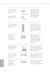
... HDD. To use a 20-pin ATX power supply, please plug it along Pin 1 and Pin 5. Please connect a hunderbolt™ add-in card (AIC) to this connector to this connector via the GPIO cable. Please connect a 4 pin molex power cable to connect a 3-Pin CPU fan, please connect it along Pin 1 and Pin 13. his motherboard provides a 4-Pin CPU fan (Quiet Fan) connector. English 24 If you plan to this connector when more than three graphics cards are installed. ATX Power Connector (24-pin ATXPWR1) (see p.6, No. 8) ATX 12V Power Connector (8-pin ATX12V1) (see p.6, No. 3) PCIe Power...
... HDD. To use a 20-pin ATX power supply, please plug it along Pin 1 and Pin 5. Please connect a hunderbolt™ add-in card (AIC) to this connector to this connector via the GPIO cable. Please connect a 4 pin molex power cable to connect a 3-Pin CPU fan, please connect it along Pin 1 and Pin 13. his motherboard provides a 4-Pin CPU fan (Quiet Fan) connector. English 24 If you plan to this connector when more than three graphics cards are installed. ATX Power Connector (24-pin ATXPWR1) (see p.6, No. 8) ATX 12V Power Connector (8-pin ATX12V1) (see p.6, No. 3) PCIe Power...
User Manual
Page 38
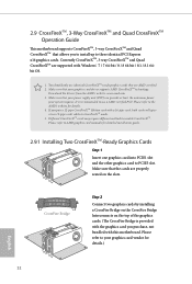
... installation guide. 2.9.1 Installing Two CrossFireXTM-Ready Graphics Cards Step 1 Insert one graphics card into PCIE1 slot and the other graphics card to three identical PCI Express x16 graphics cards. 2.9 CrossFireXTM, 3-Way CrossFireXTM and Quad CrossFireXTM Operation Guide his motherboard supports CrossFireXTM, 3-way CrossFireXTM and Quad CrossFireXTM that are supported with a 16-pipe card, both cards will operate as 12-pipe cards while in CrossFireXTM mode. 5. Please refer to enable CrossFireXTM. Please refer to AMD graphics card manuals...
... installation guide. 2.9.1 Installing Two CrossFireXTM-Ready Graphics Cards Step 1 Insert one graphics card into PCIE1 slot and the other graphics card to three identical PCI Express x16 graphics cards. 2.9 CrossFireXTM, 3-Way CrossFireXTM and Quad CrossFireXTM Operation Guide his motherboard supports CrossFireXTM, 3-way CrossFireXTM and Quad CrossFireXTM that are supported with a 16-pipe card, both cards will operate as 12-pipe cards while in CrossFireXTM mode. 5. Please refer to enable CrossFireXTM. Please refer to AMD graphics card manuals...

User Manual
Page 41
... your graphics card and click Apply. Step 3 Install the required drivers and CATALYST Control Center then restart your computer and boot into OS. We recommend using this utility to uninstall any VGA drivers installed in the Windows® system tray. English 35 he Catalyst Uninstaller is an optional download. hen select Enable AMD CrossFireX and click Apply. Please check AMD's website for details. Please check AMD's website for AMD driver updates...
... your graphics card and click Apply. Step 3 Install the required drivers and CATALYST Control Center then restart your computer and boot into OS. We recommend using this utility to uninstall any VGA drivers installed in the Windows® system tray. English 35 he Catalyst Uninstaller is an optional download. hen select Enable AMD CrossFireX and click Apply. Please check AMD's website for details. Please check AMD's website for AMD driver updates...

User Manual
Page 45
... 3.2 "A-Tuning" in this motherboard allows you to two SATA HDDs. 2. Connection Diagram 1 HDD Saver Cable 2 SATA data cable *he HDD Saver Connector supports up to switch on and off the connected HDDs via sotware when needed. hen connect the SATA power connector(s) to the HDD Saver Connector (SATA_ PWR_1) placed near the SATA ports. X99 Extreme4 2.11 HDD Saver Cable Installation Guide The HDD Saver Connector on this user manual. 39 English hen connect the other end to your SATA HDD(s). * he diagram shown here is for...
... 3.2 "A-Tuning" in this motherboard allows you to two SATA HDDs. 2. Connection Diagram 1 HDD Saver Cable 2 SATA data cable *he HDD Saver Connector supports up to switch on and off the connected HDDs via sotware when needed. hen connect the SATA power connector(s) to the HDD Saver Connector (SATA_ PWR_1) placed near the SATA ports. X99 Extreme4 2.11 HDD Saver Cable Installation Guide The HDD Saver Connector on this user manual. 39 English hen connect the other end to your SATA HDD(s). * he diagram shown here is for...

User Manual
Page 46
..., the drivers you install can work properly. Utilities Menu he drivers compatible to install it. If the Main Menu does not appear automatically, locate and double click on the support CD driver page. Please click Install All or follow the installation wizard to your system will be auto-detected and listed on the ile "ASRSETUP.EXE" in your computer. Chapter 3 Software and Utilities Operation 3.1 Installing Drivers he CD automatically displays the Main Menu if...
..., the drivers you install can work properly. Utilities Menu he drivers compatible to install it. If the Main Menu does not appear automatically, locate and double click on the support CD driver page. Please click Install All or follow the installation wizard to your system will be auto-detected and listed on the ile "ASRSETUP.EXE" in your computer. Chapter 3 Software and Utilities Operation 3.1 Installing Drivers he CD automatically displays the Main Menu if...
User Manual
Page 81
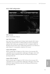
... it is enabled in BIOS). Legacy USB 3.0 Support Enable or disable Legacy OS Support for USB 2.0 devices. Set [Enabled] to keep the USB 3.0 driver enabled (Must install driver to keep the USB 3.0 driver enabled ater rebooting (USB 3.0 is recommended to disable the USB 3.0 ports. If you encounter USB compatibility issues it is disabled in BIOS). Select UEFI Setup Only to disable legacy USB support. 4.4.6 USB Coniguration X99 Extreme4 USB Controller Enable or disable all the USB ports. Set [Smart Auto] to use USB devices under the UEFI setup and Windows/Linux operating...
... it is enabled in BIOS). Legacy USB 3.0 Support Enable or disable Legacy OS Support for USB 2.0 devices. Set [Enabled] to keep the USB 3.0 driver enabled (Must install driver to keep the USB 3.0 driver enabled ater rebooting (USB 3.0 is recommended to disable the USB 3.0 ports. If you encounter USB compatibility issues it is disabled in BIOS). Select UEFI Setup Only to disable legacy USB support. 4.4.6 USB Coniguration X99 Extreme4 USB Controller Enable or disable all the USB ports. Set [Smart Auto] to use USB devices under the UEFI setup and Windows/Linux operating...

User Manual
Page 85
... ROM. 79 English X99 Extreme4 Re-detect SATA Power Connection Re-detect your system via the HDD Saver application under your USB pen drive before using this function. You can start installing the operating system in the UEFI that installs the LAN driver to your SATA Power connection. Please setup network coniguration before using UEFI Tech Service. DHCP (Auto IP), Auto ASRock Internet Flash downloads and updates the latest UEFI irmware version from the support CD to update your HDD coniguration. Please setup network coniguration before using Internet Flash...
... ROM. 79 English X99 Extreme4 Re-detect SATA Power Connection Re-detect your system via the HDD Saver application under your USB pen drive before using this function. You can start installing the operating system in the UEFI that installs the LAN driver to your SATA Power connection. Please setup network coniguration before using UEFI Tech Service. DHCP (Auto IP), Auto ASRock Internet Flash downloads and updates the latest UEFI irmware version from the support CD to update your HDD coniguration. Please setup network coniguration before using Internet Flash...

User Manual
Page 86
Save User Default Type a proile name and press enter to download the UEFI irmware. Load User Default Load previously saved user defaults. 80 English UEFI Download Server Select a server to save your settings as user default. Network Coniguration Use this to conigure internet connection settings for Internet Flash. Internet Setting Enable or disable sound efects in the setup utility.
Save User Default Type a proile name and press enter to download the UEFI irmware. Load User Default Load previously saved user defaults. 80 English UEFI Download Server Select a server to save your settings as user default. Network Coniguration Use this to conigure internet connection settings for Internet Flash. Internet Setting Enable or disable sound efects in the setup utility.
Quick Installation Guide
Page 4
... Connectors (SATA3_0_1) 14 SATA3 Connectors (SATA3_2_3) 15 SATA3 Connectors (SATA3_4_5) 16 Chassis Fan Connector (CHA_FAN2) 17 Chassis Fan Connector (CHA_FAN1) 18 Power LED Header (PLED1) 19 Chassis Speaker Header (SPEAKER1) 20 System Panel Header (PANEL1) 21 HDD Saver Connector (SATA_PWR_1) 22 USB 2.0 Header (USB4_5) 23 USB 2.0 Header (USB6_7) 24 BIOS Selection Jumper (BIOS_SEL1) 25 Clear CMOS Jumper (CLRCMOS1) 26 COM Port Header (COM1) 27 TPM Header (TPMS1) 28 Front Panel Audio Header (HD_AUDIO1) 29 hunderbolt AIC Connector (TBT1) 30 PCIe Power Connector (PCIE_PWR1) 31 Power Fan Connector...
... Connectors (SATA3_0_1) 14 SATA3 Connectors (SATA3_2_3) 15 SATA3 Connectors (SATA3_4_5) 16 Chassis Fan Connector (CHA_FAN2) 17 Chassis Fan Connector (CHA_FAN1) 18 Power LED Header (PLED1) 19 Chassis Speaker Header (SPEAKER1) 20 System Panel Header (PANEL1) 21 HDD Saver Connector (SATA_PWR_1) 22 USB 2.0 Header (USB4_5) 23 USB 2.0 Header (USB6_7) 24 BIOS Selection Jumper (BIOS_SEL1) 25 Clear CMOS Jumper (CLRCMOS1) 26 COM Port Header (COM1) 27 TPM Header (TPMS1) 28 Front Panel Audio Header (HD_AUDIO1) 29 hunderbolt AIC Connector (TBT1) 30 PCIe Power Connector (PCIE_PWR1) 31 Power Fan Connector...
Quick Installation Guide
Page 10
... PCI Express module up to Gen3 x4 (32 Gb/s) Connector • 1 x COM Port Header • 1 x TPM Header • 1 x Power LED Header • 2 x CPU Fan Connectors (1 x 4-pin, 1 x 3-pin) • 3 x Chassis Fan Connectors (1 x 4-pin, 2 x 3-pin) (Smart Fan Speed Control) • 1 x Power Fan Connector (3-pin) • 1 x 24 pin ATX Power Connector • 1 x 8 pin 12V Power Connector (Hi-Density Power Connector) • 1 x HDD Saver Connector • 1 x PCIe Power Connector • 1 x Front Panel Audio Connector • 1 x hunderbolt AIC Connector • 2 x USB 2.0 Headers (support...
... PCI Express module up to Gen3 x4 (32 Gb/s) Connector • 1 x COM Port Header • 1 x TPM Header • 1 x Power LED Header • 2 x CPU Fan Connectors (1 x 4-pin, 1 x 3-pin) • 3 x Chassis Fan Connectors (1 x 4-pin, 2 x 3-pin) (Smart Fan Speed Control) • 1 x Power Fan Connector (3-pin) • 1 x 24 pin ATX Power Connector • 1 x 8 pin 12V Power Connector (Hi-Density Power Connector) • 1 x HDD Saver Connector • 1 x PCIe Power Connector • 1 x Front Panel Audio Connector • 1 x hunderbolt AIC Connector • 2 x USB 2.0 Headers (support...

Quick Installation Guide
Page 26
...three graphics cards are installed. Please connect a 4 pin molex power cable to manage the power state of HDD. Please connect the HDD Saver Cable to this connector to this connector via the GPIO cable. his motherboard provides a 4-Pin CPU fan (Quiet Fan) connector. English 24 To use a 4-pin ATX power supply, please plug it to Pin 1-3. CPU Fan Connectors (4-pin CPU_FAN1) (see p.1, No. 4) (3-pin CPU_FAN2) (see p.1, No. 29) 12 24 1 13 8 5 4 1 1 his motherboard provides a 24-pin ATX power connector. ATX Power Connector (24-pin ATXPWR1) (see p.1, No. 8) ATX 12V Power...
...three graphics cards are installed. Please connect a 4 pin molex power cable to manage the power state of HDD. Please connect the HDD Saver Cable to this connector to this connector via the GPIO cable. his motherboard provides a 4-Pin CPU fan (Quiet Fan) connector. English 24 To use a 4-pin ATX power supply, please plug it to Pin 1-3. CPU Fan Connectors (4-pin CPU_FAN1) (see p.1, No. 4) (3-pin CPU_FAN2) (see p.1, No. 29) 12 24 1 13 8 5 4 1 1 his motherboard provides a 24-pin ATX power connector. ATX Power Connector (24-pin ATXPWR1) (see p.1, No. 8) ATX 12V Power...

Quick Installation Guide
Page 32
hen connect the SATA power connector(s) to your SATA HDD(s). Connection Diagram 1 HDD Saver Cable 2 SATA data cable *he HDD Saver Connector supports up to switch on and off the connected HDDs via sotware when needed. Connect one end of the HDD Saver Cable to the section 3.2 "A-Tuning" in the user manual. 30 English Connect one end of the SATA data cable to a SATA port on the motherboard. 2.9 HDD Saver Cable Installation Guide The HDD Saver Connector on this motherboard allows you to two SATA HDDs. 2. Please follow the...
hen connect the SATA power connector(s) to your SATA HDD(s). Connection Diagram 1 HDD Saver Cable 2 SATA data cable *he HDD Saver Connector supports up to switch on and off the connected HDDs via sotware when needed. Connect one end of the HDD Saver Cable to the section 3.2 "A-Tuning" in the user manual. 30 English Connect one end of the SATA data cable to a SATA port on the motherboard. 2.9 HDD Saver Cable Installation Guide The HDD Saver Connector on this motherboard allows you to two SATA HDDs. 2. Please follow the...


