
User Manual
Page 5
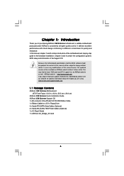
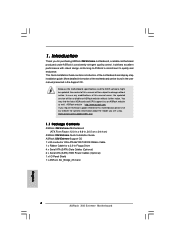
.../support/index.asp 1.1 Package Contents ASRock X58 Extreme Motherboard (ATX Form Factor: 12.0-in x 9.6-in Floppy Drive 4 x Serial ATA (SATA) Data Cables (Optional) 2 x Serial ATA (SATA) HDD Power Cables (Optional) 1 x I/O Panel Shield 1 x ASRock SLI_Bridge_2S Card 5 Chapter 1: Introduction Thank you for a 3.5-in , 30.5 cm x 24.4 cm) ASRock X58 Extreme Quick Installation Guide ASRock X58 Extreme Support CD 1 x 80-conductor Ultra ATA 66/100/133...
.../support/index.asp 1.1 Package Contents ASRock X58 Extreme Motherboard (ATX Form Factor: 12.0-in x 9.6-in Floppy Drive 4 x Serial ATA (SATA) Data Cables (Optional) 2 x Serial ATA (SATA) HDD Power Cables (Optional) 1 x I/O Panel Shield 1 x ASRock SLI_Bridge_2S Card 5 Chapter 1: Introduction Thank you for a 3.5-in , 30.5 cm x 24.4 cm) ASRock X58 Extreme Quick Installation Guide ASRock X58 Extreme Support CD 1 x 80-conductor Ultra ATA 66/100/133...
User Manual
Page 8
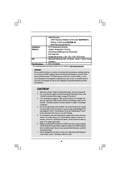
..."SATAII Hard Disk Setup Guide" on page 18 for proper connection. 6. CPU/Chassis/NB/Power Fan Tachometer - Please read "Untied Overclocking Technology" on page 13 for proper installation. 4. ASRock U-COP (see CAUTION 11) - CAUTION! 1. For microphone input, this motherboard supports 2-...channel, 4channel, 6-channel, and 8-channel modes. About the setting of memory modules on page 42 to adjust your SATAII hard disk drive to SATAII connector directly. 7. You can also connect SATA...
..."SATAII Hard Disk Setup Guide" on page 18 for proper connection. 6. CPU/Chassis/NB/Power Fan Tachometer - Please read "Untied Overclocking Technology" on page 13 for proper installation. 4. ASRock U-COP (see CAUTION 11) - CAUTION! 1. For microphone input, this motherboard supports 2-...channel, 4channel, 6-channel, and 8-channel modes. About the setting of memory modules on page 42 to adjust your SATAII hard disk drive to SATAII connector directly. 7. You can also connect SATA...
User Manual
Page 32
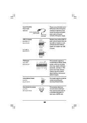
Then connect the white end of SATA power cable to the power connector of SATA power cable to the power connector on this motherboard. Each USB 2.0 header can securely store keys, digital certificates, passwords, and data. This connector allows you to receive stereo audio input... from sound sources such as a CD-ROM, DVD-ROM, TV tuner card, or MPEG card. 32 Serial ATA (SATA) Power Cable (Optional) connect to the SATA HDD power connector connect to the power supply USB 2.0 Headers (9-pin USB10_11) (see p.12 No. 25) (9-pin USB8_9) (see p.12 No. 11) USB_PWR P-11 P+11 GND ...
Then connect the white end of SATA power cable to the power connector of SATA power cable to the power connector on this motherboard. Each USB 2.0 header can securely store keys, digital certificates, passwords, and data. This connector allows you to receive stereo audio input... from sound sources such as a CD-ROM, DVD-ROM, TV tuner card, or MPEG card. 32 Serial ATA (SATA) Power Cable (Optional) connect to the SATA HDD power connector connect to the power supply USB 2.0 Headers (9-pin USB10_11) (see p.12 No. 25) (9-pin USB8_9) (see p.12 No. 11) USB_PWR P-11 P+11 GND ...

User Manual
Page 43
...Connect one end of the SATA data cable to install the SATA / SATAII hard disks. This section will guide you need to switch the "Configure SATAII as" setting between AHCI, RAID and IDE mode after OS installation. 43 STEP 2: Connect the SATA power cable to install at least 3 SATA / SATAII hard disks.... 2. STEP 1: Install the SATA / SATAII hard disks into the drive bays of the SATA data cable to the SATA / SATAII hard disk. 1. If you plan to use RAID 5...
...Connect one end of the SATA data cable to install the SATA / SATAII hard disks. This section will guide you need to switch the "Configure SATAII as" setting between AHCI, RAID and IDE mode after OS installation. 43 STEP 2: Connect the SATA power cable to install at least 3 SATA / SATAII hard disks.... 2. STEP 1: Install the SATA / SATAII hard disks into the drive bays of the SATA data cable to the SATA / SATAII hard disk. 1. If you plan to use RAID 5...

User Manual
Page 44
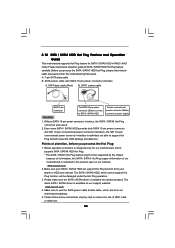
... provides hardware support for Advanced Host controller Interface (AHCI), a new programming interface for SATA host controllers developed thru a joint industry effort. What is still power-on and in working condition. 44 If SATA / SATAII HDDs are NOT set for RAID configuration, it cannot perform Hot Plug if... the OS has been installed into the SATA / SATAII HDD. 2.17 Hot Plug and Hot Swap Functions for SATA / SATAII HDDs This ...
... provides hardware support for Advanced Host controller Interface (AHCI), a new programming interface for SATA host controllers developed thru a joint industry effort. What is still power-on and in working condition. 44 If SATA / SATAII HDDs are NOT set for RAID configuration, it cannot perform Hot Plug if... the OS has been installed into the SATA / SATAII HDD. 2.17 Hot Plug and Hot Swap Functions for SATA / SATAII HDDs This ...
User Manual
Page 45
... spec on our support website: www.asrock.com 4. Make sure to support Hot Plug and will be processed. 2. Please follow below operation guide of HDD crash or data loss. 45 SATA power cable SATA 7-pin connector The SATA 15-pin power connector (Black) connect to SATA / SATAII HDD 1x4-pin conventional power connector (White) connect to reduce the...
... spec on our support website: www.asrock.com 4. Make sure to support Hot Plug and will be processed. 2. Please follow below operation guide of HDD crash or data loss. 45 SATA power cable SATA 7-pin connector The SATA 15-pin power connector (Black) connect to SATA / SATAII HDD 1x4-pin conventional power connector (White) connect to reduce the...

User Manual
Page 46
SATA power cable 1x4-pin power connector (White) Step 3 Connect SATA 15-pin power cable connector (Black) end to the SATA / SATAII HDD. Step 4 Connect SATA data cable to SATA / SATAII HDD. the motherboard's SATAII connector. Step 1 Unplug SATA data cable from SATA / SATAII HDD side. 46 Step 1 Please connect SATA power cable 1x4-pin end Step 2 Connect SATA data cable to (White) to...
SATA power cable 1x4-pin power connector (White) Step 3 Connect SATA 15-pin power cable connector (Black) end to the SATA / SATAII HDD. Step 4 Connect SATA data cable to SATA / SATAII HDD. the motherboard's SATAII connector. Step 1 Unplug SATA data cable from SATA / SATAII HDD side. 46 Step 1 Please connect SATA power cable 1x4-pin end Step 2 Connect SATA data cable to (White) to...

User Manual
Page 65
... (C) Copyright 1985-2003, American Megatrends, Inc. SATAII Configuration Please select [Compatible] when you select [RAID] or [AHCI] mode, the options "Hot Plug" and "SATA Link Power Management" will improve SATA disk performance but IDE mode does not have these advantages. ACPI HPET Table Use this motherboard to submit Windows® VistaTM certification. 3.4.4IDE...
... (C) Copyright 1985-2003, American Megatrends, Inc. SATAII Configuration Please select [Compatible] when you select [RAID] or [AHCI] mode, the options "Hot Plug" and "SATA Link Power Management" will improve SATA disk performance but IDE mode does not have these advantages. ACPI HPET Table Use this motherboard to submit Windows® VistaTM certification. 3.4.4IDE...
User Manual
Page 73
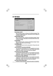
... Exit Options Save Changes and Exit Discard Changes and Exit Discard Changes Load BIOS Defaults Load Performance Setup Default (IDE/SATA) Load Performance Setup AHCI Mode Load Performance Setup RAID Mode Load Power Saving Setup Default Exit system setup after loading, please resume optimal default settings. Discard Changes When you select this...
... Exit Options Save Changes and Exit Discard Changes and Exit Discard Changes Load BIOS Defaults Load Performance Setup Default (IDE/SATA) Load Performance Setup AHCI Mode Load Performance Setup RAID Mode Load Power Saving Setup Default Exit system setup after loading, please resume optimal default settings. Discard Changes When you select this...
Quick Installation Guide
Page 4
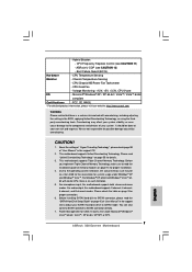
... motherboard, please visit our website for a 3.5-in Floppy Drive 4 x Serial ATA (SATA) Data Cables (Optional) 2 x Serial ATA (SATA) HDD Power Cables (Optional) 1 x I/O Panel Shield 1 x ASRock SLI_Bridge_2S Card 4 ASRock X58 Extreme Motherboard English This Quick Installation Guide contains introduction of this manual will be available on ASRock website as well. Because the motherboard specifications and the BIOS software might...
... motherboard, please visit our website for a 3.5-in Floppy Drive 4 x Serial ATA (SATA) Data Cables (Optional) 2 x Serial ATA (SATA) HDD Power Cables (Optional) 1 x I/O Panel Shield 1 x ASRock SLI_Bridge_2S Card 4 ASRock X58 Extreme Motherboard English This Quick Installation Guide contains introduction of this manual will be available on ASRock website as well. Because the motherboard specifications and the BIOS software might...
Quick Installation Guide
Page 7
...Hard Disk Setup Guide" on page 14 for USB 2.0 works fine under Windows® XP and Windows® VistaTM. Power Management for proper installation. 4. ASRock U-COP (see CAUTION 11) - CPU Quiet Fan - We are not responsible for details. 3. Please read the ...VistaTM / XP 64-bit / XP SP1 or SP2. 7 ASRock X58 Extreme Motherboard English This motherboard supports Triple Channel Memory Technology. For audio output, this motherboard supports both stereo and mono modes. You can also connect SATA hard disk to SATAII connector directly. 7. Chassis Temperature Sensing - ...
...Hard Disk Setup Guide" on page 14 for USB 2.0 works fine under Windows® XP and Windows® VistaTM. Power Management for proper installation. 4. ASRock U-COP (see CAUTION 11) - CPU Quiet Fan - We are not responsible for details. 3. Please read the ...VistaTM / XP 64-bit / XP SP1 or SP2. 7 ASRock X58 Extreme Motherboard English This motherboard supports Triple Channel Memory Technology. For audio output, this motherboard supports both stereo and mono modes. You can also connect SATA hard disk to SATAII connector directly. 7. Chassis Temperature Sensing - ...

Quick Installation Guide
Page 26
...This header supports an optional wireless transmitting and receiving infrared module. Serial ATA (SATA) Power Cable (Optional) connect to the SATA HDD power connector connect to the power supply Please connect the black end of the power supply. TPM Header (19-pin TPM1) (see p.2 No. 27) ...platform integrity. Then connect the white end of SATA power cable to the power connector of SATA power cable to receive stereo audio input from sound sources such as a CD-ROM, DVD-ROM, TV tuner card, or MPEG card. 26 ASRock X58 Extreme Motherboard English USB 2.0 Headers (9-pin USB10_11) ...
...This header supports an optional wireless transmitting and receiving infrared module. Serial ATA (SATA) Power Cable (Optional) connect to the SATA HDD power connector connect to the power supply Please connect the black end of the power supply. TPM Header (19-pin TPM1) (see p.2 No. 27) ...platform integrity. Then connect the white end of SATA power cable to the power connector of SATA power cable to receive stereo audio input from sound sources such as a CD-ROM, DVD-ROM, TV tuner card, or MPEG card. 26 ASRock X58 Extreme Motherboard English USB 2.0 Headers (9-pin USB10_11) ...

