
User Manual
Page 3
Contents 1 Introduction 5 1.1 Package Contents 5 1.2 Specifications 6 1.3 Two SLITM Graphics Card Support List 10 1.4 Two CrossFireXTM Graphics Card Support List 11 1.5 Three CrossFireXTM Graphics Card Support List .......... 11 1.6 Motherboard Layout 12 1.7 I/O Panel 13 2 Installation 14 2.1 Screw Holes 14 2.2 Pre-installation Precautions 14 2.3 CPU Installation 15 2.4 Installation of Heatsink and CPU fan ...
Contents 1 Introduction 5 1.1 Package Contents 5 1.2 Specifications 6 1.3 Two SLITM Graphics Card Support List 10 1.4 Two CrossFireXTM Graphics Card Support List 11 1.5 Three CrossFireXTM Graphics Card Support List .......... 11 1.6 Motherboard Layout 12 1.7 I/O Panel 13 2 Installation 14 2.1 Screw Holes 14 2.2 Pre-installation Precautions 14 2.3 CPU Installation 15 2.4 Installation of Heatsink and CPU fan ...
User Manual
Page 4
... Configuration 68 3.4.8 USB Configuration 69 3.5 Hardware Health Event Monitoring Screen 70 3.6 Boot Screen 71 3.6.1 Boot Settings Configuration 71 3.7 Security Screen 72 3.8 Exit Screen 73 4 Software Support 74 4.1 Install Operating System 74 4.2 Support CD Information 74 4.2.1 Running Support CD 74 4.2.2 Drivers Menu 74 4.2.3 Utilities Menu 74 4.2.4 Contact Information 74 4
... Configuration 68 3.4.8 USB Configuration 69 3.5 Hardware Health Event Monitoring Screen 70 3.6 Boot Screen 71 3.6.1 Boot Settings Configuration 71 3.7 Security Screen 72 3.8 Exit Screen 73 4 Software Support 74 4.1 Install Operating System 74 4.2 Support CD Information 74 4.2.1 Running Support CD 74 4.2.2 Drivers Menu 74 4.2.3 Utilities Menu 74 4.2.4 Contact Information 74 4
User Manual
Page 5
... (SATA) HDD Power Cables (Optional) 1 x I/O Panel Shield 1 x ASRock SLI_Bridge_2S Card 5 ASRock website http://www.asrock.com If you require technical support related to the hardware installation. www.asrock.com/support/index.asp 1.1 Package Contents ASRock X58 Extreme Motherboard (ATX Form Factor: 12.0-in x 9.6-in, 30.5 cm x 24.4 cm) ASRock X58 Extreme Quick Installation Guide ASRock X58 Extreme Support CD 1 x 80-conductor Ultra ATA 66/100/133...
... (SATA) HDD Power Cables (Optional) 1 x I/O Panel Shield 1 x ASRock SLI_Bridge_2S Card 5 ASRock website http://www.asrock.com If you require technical support related to the hardware installation. www.asrock.com/support/index.asp 1.1 Package Contents ASRock X58 Extreme Motherboard (ATX Form Factor: 12.0-in x 9.6-in, 30.5 cm x 24.4 cm) ASRock X58 Extreme Quick Installation Guide ASRock X58 Extreme Support CD 1 x 80-conductor Ultra ATA 66/100/133...
User Manual
Page 6
System Bus up to 6400 MT/s; Intel® QuickPath Interconnect - Southbridge: Intel® ICH10R - Supports Wake-On-LAN I /O - Supports Hyper-Threading Technology (see CAUTION 3) - 6 x DDR3 DIMM slots - Northbridge: Intel® X58 - Max. Supports Intel® Extreme Memory Profile (XMP) - 3 x PCI Express 2.0 x16 slots (blue @ x16 mode, orange @ x4 mode) (Double-wide slot spacing between each PCI...
System Bus up to 6400 MT/s; Intel® QuickPath Interconnect - Southbridge: Intel® ICH10R - Supports Wake-On-LAN I /O - Supports Hyper-Threading Technology (see CAUTION 3) - 6 x DDR3 DIMM slots - Northbridge: Intel® X58 - Max. Supports Intel® Extreme Memory Profile (XMP) - 3 x PCI Express 2.0 x16 slots (blue @ x16 mode, orange @ x4 mode) (Double-wide slot spacing between each PCI...

User Manual
Page 7
... - 1 x IR header - 1 x COM port header - 1 x HDMI_SPDIF header - 1 x IEEE 1394 header - 1 x TPM header - ACPI 1.1 Compliance Wake Up Events - SMBIOS 2.3.1 Support - Supports I. Intelligent Energy Saver (see CAUTION 8) - T. (Intelligent Overclocking Technology) - ASRock OC Tuner (see CAUTION 9) - Instant Boot - ASRock Instant Flash (see CAUTION 7) - 1 x Clear CMOS Switch - 1 x Power Switch - 1 x Reset Switch - 8Mb AMI BIOS - CPU, DRAM, NB, SB...
... - 1 x IR header - 1 x COM port header - 1 x HDMI_SPDIF header - 1 x IEEE 1394 header - 1 x TPM header - ACPI 1.1 Compliance Wake Up Events - SMBIOS 2.3.1 Support - Supports I. Intelligent Energy Saver (see CAUTION 8) - T. (Intelligent Overclocking Technology) - ASRock OC Tuner (see CAUTION 9) - Instant Boot - ASRock Instant Flash (see CAUTION 7) - 1 x Clear CMOS Switch - 1 x Power Switch - 1 x Reset Switch - 8Mb AMI BIOS - CPU, DRAM, NB, SB...
User Manual
Page 8
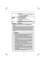
...Monitor - It should be less than 4GB for the reservation for details. 3. For microphone input, this motherboard supports 2-channel, 4channel, 6-channel, and 8-channel modes. ASRock U-COP (see CAUTION 11) - Boot Failure Guard (B.F.G.) Hardware - About the setting of memory modules on... product information, please visit our website: http://www.asrock.com WARNING Please realize that there is a certain risk involved with 64-bit CPU, there is no such limitation. 5. This motherboard supports Triple Channel Memory Technology. Before installing SATAII hard disk...
...Monitor - It should be less than 4GB for the reservation for details. 3. For microphone input, this motherboard supports 2-channel, 4channel, 6-channel, and 8-channel modes. ASRock U-COP (see CAUTION 11) - Boot Failure Guard (B.F.G.) Hardware - About the setting of memory modules on... product information, please visit our website: http://www.asrock.com WARNING Please realize that there is a certain risk involved with 64-bit CPU, there is no such limitation. 5. This motherboard supports Triple Channel Memory Technology. Before installing SATAII hard disk...
User Manual
Page 10
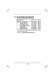
1 . 3 Two SLITM Graphics Card Support List (for Windows® XP / XP 64-bit / VistaTM / VistaTM 64-bit) Chipset Vendor NVIDIA Model Name Gigabyte GV-NX88T256H Gigabyte GV-NX88S512H-B LEADTEK PX8800 ... 9800GTX+ GeForce GTX260 182.50 182.50 182.50 182.50 182.50 182.50 182.50 182.50 * For the latest updates of the supported PCI Express VGA card list for SLITM Mode, please visit our website for details. ASRock website: http://www.asrock.com/support/index.htm 10
1 . 3 Two SLITM Graphics Card Support List (for Windows® XP / XP 64-bit / VistaTM / VistaTM 64-bit) Chipset Vendor NVIDIA Model Name Gigabyte GV-NX88T256H Gigabyte GV-NX88S512H-B LEADTEK PX8800 ... 9800GTX+ GeForce GTX260 182.50 182.50 182.50 182.50 182.50 182.50 182.50 182.50 * For the latest updates of the supported PCI Express VGA card list for SLITM Mode, please visit our website for details. ASRock website: http://www.asrock.com/support/index.htm 10
User Manual
Page 11
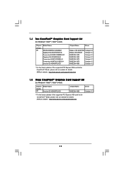
...-E3 Chipset Name RADEON 4850 Driver Catalyst 9.1 * For the latest updates of the supported PCI Express VGA card list for CrossFireXTM Mode, please visit our website for details. ASRock website: http://www.asrock.com/support/index.htm 11 1.4 Two CrossFireXTM Graphics Card Support List (for Windows® VistaTM / VistaTM 64-bit) Chipset Vendor ATI Model...
...-E3 Chipset Name RADEON 4850 Driver Catalyst 9.1 * For the latest updates of the supported PCI Express VGA card list for CrossFireXTM Mode, please visit our website for details. ASRock website: http://www.asrock.com/support/index.htm 11 1.4 Two CrossFireXTM Graphics Card Support List (for Windows® VistaTM / VistaTM 64-bit) Chipset Vendor ATI Model...
User Manual
Page 17
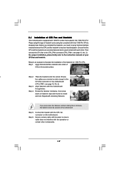
... fasteners. Rotate the fastener clockwise, then press down the fasteners without rotating them clockwise, the heatsink cannot be secured on the socket surface. Ensure that supports Intel 1366-Pin CPU. For proper installation, please kindly refer to the instruction manuals of heatsink and cooling fan compliant with tie-wrap to install...
... fasteners. Rotate the fastener clockwise, then press down the fasteners without rotating them clockwise, the heatsink cannot be secured on the socket surface. Ensure that supports Intel 1366-Pin CPU. For proper installation, please kindly refer to the instruction manuals of heatsink and cooling fan compliant with tie-wrap to install...
User Manual
Page 18
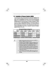
...DDR3_C2 slot. 3. In other words, you have to Intel® CPU spec definition, XMP DIMMs and DDR3 2000/ 1866/1600 are supported for one DIMM is then mapped for the first priority. 2. This motherboard also allows you always need to Intel® CPU spec ...Populated - The system maps the total size of Memory Modules (DIMM) This motherboard provides six 240-pin DDR3 (Double Data Rate 3) DIMM slots, and supports Triple Channel Memory Technology. Recommended Memory Configurations DDR3_A2 DDR3_A1 DDR3_B2 DDR3_B1 DDR3_C2 DDR3_C1 (Blue) (White) (Blue) (White) (Blue) (White) 1 DIMM ...
...DDR3_C2 slot. 3. In other words, you have to Intel® CPU spec definition, XMP DIMMs and DDR3 2000/ 1866/1600 are supported for one DIMM is then mapped for the first priority. 2. This motherboard also allows you always need to Intel® CPU spec ...Populated - The system maps the total size of Memory Modules (DIMM) This motherboard provides six 240-pin DDR3 (Double Data Rate 3) DIMM slots, and supports Triple Channel Memory Technology. Recommended Memory Configurations DDR3_A2 DDR3_A1 DDR3_B2 DDR3_B1 DDR3_C2 DDR3_C1 (Blue) (White) (Blue) (White) (Blue) (White) 1 DIMM ...
User Manual
Page 20
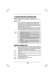
... / PCIE4 (PCIE x16 slot; Orange) is used for PCI Express x16 lane width graphics cards, or used to install PCI Express graphics cards to support 3-Way CrossFireXTM function. 1. In CrossFireXTM mode or SLITM mode, please install PCI Express x16 graphics cards on PCIE2, PCIE4 and PCIE5 slots. Please read...chassis with x1 lane width cards, such as Gigabit LAN card, SATA2 card, etc., or used to install PCI Express graphics cards to support CrossFireXTM or SLITM function. Therefore, PCIE2 and PCIE4 slots will work at x16 bandwidth while PCIE5 slot will work at x16 bandwidth. 3. Step 6.
... / PCIE4 (PCIE x16 slot; Orange) is used for PCI Express x16 lane width graphics cards, or used to install PCI Express graphics cards to support 3-Way CrossFireXTM function. 1. In CrossFireXTM mode or SLITM mode, please install PCI Express x16 graphics cards on PCIE2, PCIE4 and PCIE5 slots. Please read...chassis with x1 lane width cards, such as Gigabit LAN card, SATA2 card, etc., or used to install PCI Express graphics cards to support CrossFireXTM or SLITM function. Therefore, PCIE2 and PCIE4 slots will work at x16 bandwidth while PCIE5 slot will work at x16 bandwidth. 3. Step 6.
User Manual
Page 21
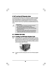
... power supply unit (PSU) can provide at least the minimum power required by your graphics card driver supports NVIDIA® SLITM technology. Step2. NVIDIA® Quad SLITM technology support Windows® VistaTM and VistaTM 64-bit OS only. Requirements 1. Make sure that the cards are ... Setup 2.7.1.1 Installing Two SLITM-Ready Graphics Cards Step 1. Please refer to the PCI Express graphics cards. 21 Currently, NVIDIA® SLITM technology supports Windows® XP, XP 64-bit, VistaTM and VistaTM 64-bit OS. Make sure that are NVIDIA® certified because different types of ...
... power supply unit (PSU) can provide at least the minimum power required by your graphics card driver supports NVIDIA® SLITM technology. Step2. NVIDIA® Quad SLITM technology support Windows® VistaTM and VistaTM 64-bit OS only. Requirements 1. Make sure that the cards are ... Setup 2.7.1.1 Installing Two SLITM-Ready Graphics Cards Step 1. Please refer to the PCI Express graphics cards. 21 Currently, NVIDIA® SLITM technology supports Windows® XP, XP 64-bit, VistaTM and VistaTM 64-bit OS. Make sure that are NVIDIA® certified because different types of ...
User Manual
Page 25
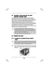
Currently CrossFireXTM feature is supported with Windows® XP with Service Pack 2 and VistaTM OS. 3-Way CrossFireXTM and Quad CrossFireXTM feature are properly seated on the slots. 25 ... a CrossFireXTM Edition co-processor graphics card, must be installed correctly to PCIE4 slot. 2.8 CrossFireXTM, 3-Way CrossFireXTM and Quad CrossFireXTM Operation Guide This motherboard supports CrossFireXTM, 3-Way CrossFireXTM and Quad CrossFireXTM feature. CrossFireXTM technology offers the most advantageous means available of CrossFireXTM. Insert one Radeon graphics card into PCIE2 slot...
Currently CrossFireXTM feature is supported with Windows® XP with Service Pack 2 and VistaTM OS. 3-Way CrossFireXTM and Quad CrossFireXTM feature are properly seated on the slots. 25 ... a CrossFireXTM Edition co-processor graphics card, must be installed correctly to PCIE4 slot. 2.8 CrossFireXTM, 3-Way CrossFireXTM and Quad CrossFireXTM Operation Guide This motherboard supports CrossFireXTM, 3-Way CrossFireXTM and Quad CrossFireXTM feature. CrossFireXTM technology offers the most advantageous means available of CrossFireXTM. Insert one Radeon graphics card into PCIE2 slot...
User Manual
Page 30
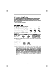
... of Surround Display feature. However, please do not clear the CMOS right after you do the clearCMOS action. 30 2.9 Surround Display Feature This motherboard supports Surround Display upgrade. Clear CMOS Jumper (CLRCMOS1) (see p.12, No. 1) 2_3 Short pin2, pin3 to enable +5VSB (standby) for 15 seconds...password, date, time, and system setup parameters. To clear and reset the system parameters to the document at the following path in the Support CD: ..\ Surround Display Information 2.10 Jumpers Setup The illustration shows how jumpers are "Short" when jumper cap is "Short". If ...
... of Surround Display feature. However, please do not clear the CMOS right after you do the clearCMOS action. 30 2.9 Surround Display Feature This motherboard supports Surround Display upgrade. Clear CMOS Jumper (CLRCMOS1) (see p.12, No. 1) 2_3 Short pin2, pin3 to enable +5VSB (standby) for 15 seconds...password, date, time, and system setup parameters. To clear and reset the system parameters to the document at the following path in the Support CD: ..\ Surround Display Information 2.10 Jumpers Setup The illustration shows how jumpers are "Short" when jumper cap is "Short". If ...
User Manual
Page 31
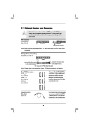
... the cable is plugged into Pin1 side of the motherboard! FDD connector (33-pin FLOPPY1) (see p.12, No. 17) These six Serial ATAII (SATAII) connectors support SATA data cables for the details. Do NOT place jumper caps over the headers and connectors will cause permanent damage of the connector. Placing jumper...
... the cable is plugged into Pin1 side of the motherboard! FDD connector (33-pin FLOPPY1) (see p.12, No. 17) These six Serial ATAII (SATAII) connectors support SATA data cables for the details. Do NOT place jumper caps over the headers and connectors will cause permanent damage of the connector. Placing jumper...
User Manual
Page 32
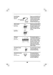
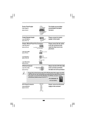
Then connect the white end of the power supply. This connector supports a Trusted Platform Module (TPM) system, which can support two USB 2.0 ports. Serial ATA (SATA) Power Cable (Optional) connect to the SATA HDD power connector connect to the power supply ... protects digital identities, and ensures platform integrity. Each USB 2.0 header can securely store keys, digital certificates, passwords, and data. This header supports an optional wireless transmitting and receiving infrared module. Besides seven default USB 2.0 ports on the I/O panel, there are two USB 2.0 headers on each...
Then connect the white end of the power supply. This connector supports a Trusted Platform Module (TPM) system, which can support two USB 2.0 ports. Serial ATA (SATA) Power Cable (Optional) connect to the SATA HDD power connector connect to the power supply ... protects digital identities, and ensures platform integrity. Each USB 2.0 header can securely store keys, digital certificates, passwords, and data. This header supports an optional wireless transmitting and receiving infrared module. Besides seven default USB 2.0 ports on the I/O panel, there are two USB 2.0 headers on each...
User Manual
Page 33
High Definition Audio supports Jack Sensing, but the panel wire on the lower right hand taskbar to OUT2_L. B. Connect Ground (GND) to function correctly. E. If you use AC'97 ... below: A. Connect Audio_R (RIN) to OUT2_R and Audio_L (LIN) to enter Realtek HD Audio Manager. D. Enter Windows system. Click the icon on the chassis must support HDA to Ground (GND). For Windows® VistaTM / VistaTM 64-bit OS: Click the right-top "Folder" icon , choose "Disable front panel jack detection", and...
High Definition Audio supports Jack Sensing, but the panel wire on the lower right hand taskbar to OUT2_L. B. Connect Ground (GND) to function correctly. E. If you use AC'97 ... below: A. Connect Audio_R (RIN) to OUT2_R and Audio_L (LIN) to enter Realtek HD Audio Manager. D. Enter Windows system. Click the icon on the chassis must support HDA to Ground (GND). For Windows® VistaTM / VistaTM 64-bit OS: Click the right-top "Folder" icon , choose "Disable front panel jack detection", and...
User Manual
Page 34
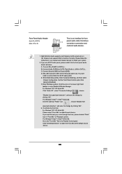
... 4 CPU_FAN_SPEED 3 +12V 2 GND 1 Please connect a CPU fan cable to this connector and match the black wire to this motherboard provides 4-Pin CPU fan (Quiet Fan) support, the 3-Pin CPU fan still can work successfully even without the fan speed control function.
... 4 CPU_FAN_SPEED 3 +12V 2 GND 1 Please connect a CPU fan cable to this connector and match the black wire to this motherboard provides 4-Pin CPU fan (Quiet Fan) support, the 3-Pin CPU fan still can work successfully even without the fan speed control function.
User Manual
Page 35
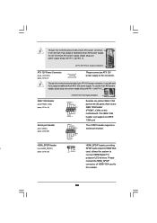
.... 10) Serial port Header (9-pin COM1) (see p.12 No. 30) SPDIFOUT +5V card, allows the system to this connector. This COM1 header supports a serial port module. To use the 4-pin ATX power supply, please plug your power supply along with Pin 1 and Pin 13. 20-Pin ATX...1394 header can still work if you adopt a traditional 20-pin ATX power supply. Though this motherboard provides 8-pin ATX 12V power connector, it can support one IEEE 1394 header (FRONT_1394) on the I/O panel, there is one IEEE 1394 port. HDMI_SPDIF Header HDMI_SPDIF header, providing n 1 (3-pin HDMI_SPDIF1...
.... 10) Serial port Header (9-pin COM1) (see p.12 No. 30) SPDIFOUT +5V card, allows the system to this connector. This COM1 header supports a serial port module. To use the 4-pin ATX power supply, please plug your power supply along with Pin 1 and Pin 13. 20-Pin ATX...1394 header can still work if you adopt a traditional 20-pin ATX power supply. Though this motherboard provides 8-pin ATX 12V power connector, it can support one IEEE 1394 header (FRONT_1394) on the I/O panel, there is one IEEE 1394 port. HDMI_SPDIF Header HDMI_SPDIF header, providing n 1 (3-pin HDMI_SPDIF1...
User Manual
Page 40
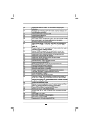
... the silent boot module. Initializes the Microsoft IRQ Routing Table. AC End of POST initialization of chipset registers. 8D Build ACPI tables (if ACPI is supported) 8E Program the peripheral parameters. Enable/Disable NMI as selected 90 Late POST initialization of runtime image preparation for total memory installed in F000h segment...
... the silent boot module. Initializes the Microsoft IRQ Routing Table. AC End of POST initialization of chipset registers. 8D Build ACPI tables (if ACPI is supported) 8E Program the peripheral parameters. Enable/Disable NMI as selected 90 Late POST initialization of runtime image preparation for total memory installed in F000h segment...


