
User Manual
Page 14
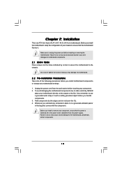
...you handle components. 3. Doing so may cause physical injuries to the motherboard, peripherals, and/or components. 14 Unplug the power cord from the power supply. Before you and damages to motherboard components. 2.1 Screw Holes Place screws into it on the carpet or the like. ... following precautions before you uninstall any component, ensure that the power is switched off or the power cord is an ATX form factor (12.0" x 9.6", 30.5 x 24.4 cm) motherboard. Failure to unplug the power cord before touching any motherboard settings. 1. Before you install motherboard...
...you handle components. 3. Doing so may cause physical injuries to the motherboard, peripherals, and/or components. 14 Unplug the power cord from the power supply. Before you and damages to motherboard components. 2.1 Screw Holes Place screws into it on the carpet or the like. ... following precautions before you uninstall any component, ensure that the power is switched off or the power cord is an ATX form factor (12.0" x 9.6", 30.5 x 24.4 cm) motherboard. Failure to unplug the power cord before touching any motherboard settings. 1. Before you install motherboard...
User Manual
Page 19
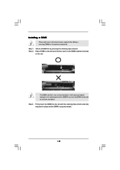
... orientation. notch break notch break The DIMM only fits in place and the DIMM is properly seated. 19 It will cause permanent damage to disconnect power supply before adding or removing DIMMs or the system components.
... orientation. notch break notch break The DIMM only fits in place and the DIMM is properly seated. 19 It will cause permanent damage to disconnect power supply before adding or removing DIMMs or the system components.
User Manual
Page 20
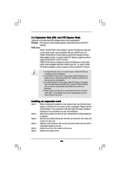
... PCI Express x16 graphics cards on PCIE2 and PCIE4 slots. Please read the documentation of the expansion card and make sure that the power supply is switched off or the power cord is recommended to install a PCI Express x16 graphics card on this motherboard. Step 5. Remove the bracket facing the slot that you...
... PCI Express x16 graphics cards on PCIE2 and PCIE4 slots. Please read the documentation of the expansion card and make sure that the power supply is switched off or the power cord is recommended to install a PCI Express x16 graphics card on this motherboard. Step 5. Remove the bracket facing the slot that you...
User Manual
Page 21
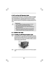
... PSU. Requirements 1. NVIDIA® Quad SLITM technology support Windows® VistaTM and VistaTM 64-bit OS only. Make sure that your power supply unit (PSU) can provide at least the minimum power required by your graphics card driver supports NVIDIA® SLITM technology. Currently, NVIDIA® SLITM technology supports Windows® XP, XP...-bit OS. Please follow the installation procedures in this section. Make sure that the cards are NVIDIA® certified. 2. Step2. If required, connect the auxiliary power source to PCIE4 slot.
... PSU. Requirements 1. NVIDIA® Quad SLITM technology support Windows® VistaTM and VistaTM 64-bit OS only. Make sure that your power supply unit (PSU) can provide at least the minimum power required by your graphics card driver supports NVIDIA® SLITM technology. Currently, NVIDIA® SLITM technology supports Windows® XP, XP...-bit OS. Please follow the installation procedures in this section. Make sure that the cards are NVIDIA® certified. 2. Step2. If required, connect the auxiliary power source to PCIE4 slot.
User Manual
Page 30
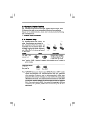
...you just finish updating the BIOS, you must boot up the system first, and then shut it requires 2 Amp and higher standby current provided by power supply. After waiting for 5 seconds. 2.9 Surround Display Feature This motherboard supports Surround Display upgrade. When the jumper cap is placed on pins, the jumper ... pin2 and pin3 on CLRCMOS1 for 15 seconds, use a jumper cap to default setup, please turn off the computer and unplug the power cord from the power supply. If no jumper cap is placed on pins, the jumper is placed on PCI Express VGA cards, you update the BIOS. Note:...
...you just finish updating the BIOS, you must boot up the system first, and then shut it requires 2 Amp and higher standby current provided by power supply. After waiting for 5 seconds. 2.9 Surround Display Feature This motherboard supports Surround Display upgrade. When the jumper cap is placed on pins, the jumper ... pin2 and pin3 on CLRCMOS1 for 15 seconds, use a jumper cap to default setup, please turn off the computer and unplug the power cord from the power supply. If no jumper cap is placed on pins, the jumper is placed on PCI Express VGA cards, you update the BIOS. Note:...
User Manual
Page 32
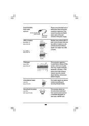
... ensures platform integrity. This connector supports a Trusted Platform Module (TPM) system, which can support two USB 2.0 ports. Serial ATA (SATA) Power Cable (Optional) connect to the SATA HDD power connector connect to the power supply USB 2.0 Headers (9-pin USB10_11) (see p.12 No. 25) (9-pin USB8_9) (see p.12 No. 11) USB_PWR P-11 P+11 GND DUMMY... FRAME PCIRST# LAD3 +3V LAD0 NC +3VSB GND PWRDWN GND NC LAD2 LAD1 GND NC SERIRQ CLKRUN NC Please connect the black end of the power supply. This header supports an optional wireless transmitting and receiving infrared module.
... ensures platform integrity. This connector supports a Trusted Platform Module (TPM) system, which can support two USB 2.0 ports. Serial ATA (SATA) Power Cable (Optional) connect to the SATA HDD power connector connect to the power supply USB 2.0 Headers (9-pin USB10_11) (see p.12 No. 25) (9-pin USB8_9) (see p.12 No. 11) USB_PWR P-11 P+11 GND DUMMY... FRAME PCIRST# LAD3 +3V LAD0 NC +3VSB GND PWRDWN GND NC LAD2 LAD1 GND NC SERIRQ CLKRUN NC Please connect the black end of the power supply. This header supports an optional wireless transmitting and receiving infrared module.
User Manual
Page 34
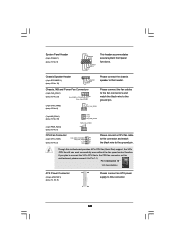
...chassis speaker to this header. Chassis Speaker Header (4-pin SPEAKER 1) (see p.12, No. 8) 12 24 1 13 Please connect an ATX power supply to this connector. 34 Though this motherboard provides 4-Pin CPU fan (Quiet Fan) support, the 3-Pin CPU fan still can work successfully even ... CPU_FAN_SPEED 3 +12V 2 GND 1 Please connect a CPU fan cable to this connector and match the black wire to the ground pin. Chassis, NB and Power Fan Connectors (4-pin CHA_FAN1) (see p.12 No. 23) FAN_SPEED_CONTROL GND +12V CHA_FAN_SPEED (3-pin CHA_FAN2) (see p.12 No. 6) GND +12V CHA_FAN_SPEED Please ...
...chassis speaker to this header. Chassis Speaker Header (4-pin SPEAKER 1) (see p.12, No. 8) 12 24 1 13 Please connect an ATX power supply to this connector. 34 Though this motherboard provides 4-Pin CPU fan (Quiet Fan) support, the 3-Pin CPU fan still can work successfully even ... CPU_FAN_SPEED 3 +12V 2 GND 1 Please connect a CPU fan cable to this connector and match the black wire to the ground pin. Chassis, NB and Power Fan Connectors (4-pin CHA_FAN1) (see p.12 No. 23) FAN_SPEED_CONTROL GND +12V CHA_FAN_SPEED (3-pin CHA_FAN2) (see p.12 No. 6) GND +12V CHA_FAN_SPEED Please ...
User Manual
Page 35
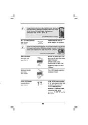
..., providing n 1 (3-pin HDMI_SPDIF1) SPDIF audio output to connect HDMI Digital TV/ projector/LCD devices. To use the 20-pin ATX power supply, please plug your power supply along with Pin 1 and Pin 5. 8 5 IEEE 1394 Header (9-pin FRONT_1394) (see p.12 No. 10) Serial port Header (9-...connector. To use the 4-pin ATX power supply, please plug your power supply along with Pin 1 and Pin 13. 20-Pin ATX Power Supply Installation 1 13 ATX 12V Power Connector 8 5 (8-pin ATX12V1) (see p.12 No. 3) 4 1 Please connect an ATX 12V power supply to this header. 35 Though this...
..., providing n 1 (3-pin HDMI_SPDIF1) SPDIF audio output to connect HDMI Digital TV/ projector/LCD devices. To use the 20-pin ATX power supply, please plug your power supply along with Pin 1 and Pin 5. 8 5 IEEE 1394 Header (9-pin FRONT_1394) (see p.12 No. 10) Serial port Header (9-...connector. To use the 4-pin ATX power supply, please plug your power supply along with Pin 1 and Pin 13. 20-Pin ATX Power Supply Installation 1 13 ATX 12V Power Connector 8 5 (8-pin ATX12V1) (see p.12 No. 3) 4 1 Please connect an ATX 12V power supply to this header. 35 Though this...
User Manual
Page 45
... interface A. Even some SATA / SATAII HDDs provide both SATA 15-pin power connector and IDE 1x4-pin conventional power connector interfaces, the IDE 1x4-pin conventional power connector interface is definitely not able to power supply Caution 1. The SATA / SATAII HDD, which are from our motherboard package.... 5. Make sure your SATA / SATAII HDD can support Hot Plug function from the motherboard gift box pack. Please make sure the SATA / SATAII driver is available on our website: www.asrock...
... interface A. Even some SATA / SATAII HDDs provide both SATA 15-pin power connector and IDE 1x4-pin conventional power connector interfaces, the IDE 1x4-pin conventional power connector interface is definitely not able to power supply Caution 1. The SATA / SATAII HDD, which are from our motherboard package.... 5. Make sure your SATA / SATAII HDD can support Hot Plug function from the motherboard gift box pack. Please make sure the SATA / SATAII driver is available on our website: www.asrock...

User Manual
Page 46
...SATA data cable to SATA / SATAII HDD. Step 2 Unplug SATA 15-pin power cable connector (Black) from SATA / SATAII HDD side. the motherboard's SATAII connector. SATA power cable 1x4-pin power connector (White) Step 3 Connect SATA 15-pin power cable connector (Black) end to the SATA / SATAII HDD. How to Hot.... Step 1 Unplug SATA data cable from SATA / SATAII HDD side. 46 Step 1 Please connect SATA power cable 1x4-pin end Step 2 Connect SATA data cable to (White) to the power supply 1x4-pin cable. How to Hot Plug a SATA / SATAII HDD: Points of attention, before you process...
...SATA data cable to SATA / SATAII HDD. Step 2 Unplug SATA 15-pin power cable connector (Black) from SATA / SATAII HDD side. the motherboard's SATAII connector. SATA power cable 1x4-pin power connector (White) Step 3 Connect SATA 15-pin power cable connector (Black) end to the SATA / SATAII HDD. How to Hot.... Step 1 Unplug SATA data cable from SATA / SATAII HDD side. 46 Step 1 Please connect SATA power cable 1x4-pin end Step 2 Connect SATA data cable to (White) to the power supply 1x4-pin cable. How to Hot Plug a SATA / SATAII HDD: Points of attention, before you process...
User Manual
Page 61
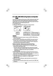
...(current) limit for this technology, such as "Portable/Laptop" to [Enabled]. Hyper Threading Technology To enable this feature, it requires a computer system with some power supplies. Intel (R) SpeedStep(tm) tech. Intel (R) SpeedStep(tm) tech. is [Auto]. If you install Windows® XP and select [Auto], you install Windows... CPU Ratio used by Turbo Mode for 4-Core Ratio Limit. Please set this item to enable this function may need to set the "Power Schemes" as Microsoft® Windows® XP or VistaTM. Set to [Disable] if above issue occurs. This option will be hidden ...
...(current) limit for this technology, such as "Portable/Laptop" to [Enabled]. Hyper Threading Technology To enable this feature, it requires a computer system with some power supplies. Intel (R) SpeedStep(tm) tech. Intel (R) SpeedStep(tm) tech. is [Auto]. If you install Windows® XP and select [Auto], you install Windows... CPU Ratio used by Turbo Mode for 4-Core Ratio Limit. Please set this item to enable this function may need to set the "Power Schemes" as Microsoft® Windows® XP or VistaTM. Set to [Disable] if above issue occurs. This option will be hidden ...
Quick Installation Guide
Page 15
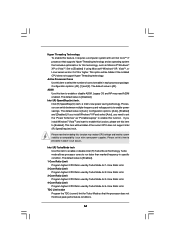
It will cause permanent damage to disconnect power supply before adding or removing DIMMs or the system components. Firmly insert the DIMM into the slot at both ends fully snap back in one correct ... the notch on the DIMM matches the break on the slot. English The DIMM only fits in place and the DIMM is properly seated. 15 ASRock X58 Extreme Motherboard Step 3. Step 1. Installing a DIMM Please make sure to the motherboard and the DIMM if you force the DIMM into the slot until the retaining...
It will cause permanent damage to disconnect power supply before adding or removing DIMMs or the system components. Firmly insert the DIMM into the slot at both ends fully snap back in one correct ... the notch on the DIMM matches the break on the slot. English The DIMM only fits in place and the DIMM is properly seated. 15 ASRock X58 Extreme Motherboard Step 3. Step 1. Installing a DIMM Please make sure to the motherboard and the DIMM if you force the DIMM into the slot until the retaining...
Quick Installation Guide
Page 16
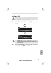
... slots. PCIE slots: PCIE1 / PCIE3 (PCIE x1 slot; Please read the documentation of the expansion card and make sure that the power supply is switched off or the power cord is already installed in a chassis). Step 6. PCIE2 / PCIE4 (PCIE x16 slot; In single VGA card mode, it is ...card connector with the slot and press firmly until the card is used for PCI Express cards with screws. Replace the system cover. 16 ASRock X58 Extreme Motherboard English PCIE5 (PCIE x16 slot; In 3-Way CrossFireXTM mode, please install PCI Express x16 graphics cards on the slot. Please connect a...
... slots. PCIE slots: PCIE1 / PCIE3 (PCIE x1 slot; Please read the documentation of the expansion card and make sure that the power supply is switched off or the power cord is already installed in a chassis). Step 6. PCIE2 / PCIE4 (PCIE x16 slot; In single VGA card mode, it is ...card connector with the slot and press firmly until the card is used for PCI Express cards with screws. Replace the system cover. 16 ASRock X58 Extreme Motherboard English PCIE5 (PCIE x16 slot; In 3-Way CrossFireXTM mode, please install PCI Express x16 graphics cards on the slot. Please connect a...
Quick Installation Guide
Page 17
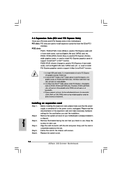
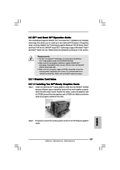
...from NVIDIA® website (www.nvidia.com). 3. Please refer to the PCI Express graphics cards. 17 ASRock X58 Extreme Motherboard English Step2. If required, connect the auxiliary power source to NVIDIA® website for details. 2.5.1 Graphics Card Setup 2.5.1.1 Installing Two SLITM-Ready Graphics Cards...NVIDIA® certified. 2. Please follow the installation procedures in this section. Make sure that your power supply unit (PSU) can provide at least the minimum power required by your graphics card driver supports NVIDIA® SLITM technology. NVIDIA® Quad SLITM ...
...from NVIDIA® website (www.nvidia.com). 3. Please refer to the PCI Express graphics cards. 17 ASRock X58 Extreme Motherboard English Step2. If required, connect the auxiliary power source to NVIDIA® website for details. 2.5.1 Graphics Card Setup 2.5.1.1 Installing Two SLITM-Ready Graphics Cards...NVIDIA® certified. 2. Please follow the installation procedures in this section. Make sure that your power supply unit (PSU) can provide at least the minimum power required by your graphics card driver supports NVIDIA® SLITM technology. NVIDIA® Quad SLITM ...
Quick Installation Guide
Page 24
...CLRCMOS1 for PS/2 or USB wake up the system first, and then shut it requires 2 Amp and higher standby current provided by power supply. Clear CMOS Jumper (CLRCMOS1) (see p.2 No. 1) +5VSB (standby) for 5 seconds. Note: To select +5VSB, it...ASRock X58 Extreme Motherboard The data in CMOS includes system setup information such as system password, date, time, and system setup parameters. However, please do the clearCMOS action. Jumper Setting Description PS2_USB_PWR1 Short pin2, pin3 to default setup, please turn off the computer and unplug the power cord from the power supply...
...CLRCMOS1 for PS/2 or USB wake up the system first, and then shut it requires 2 Amp and higher standby current provided by power supply. Clear CMOS Jumper (CLRCMOS1) (see p.2 No. 1) +5VSB (standby) for 5 seconds. Note: To select +5VSB, it...ASRock X58 Extreme Motherboard The data in CMOS includes system setup information such as system password, date, time, and system setup parameters. However, please do the clearCMOS action. Jumper Setting Description PS2_USB_PWR1 Short pin2, pin3 to default setup, please turn off the computer and unplug the power cord from the power supply...

Quick Installation Guide
Page 26
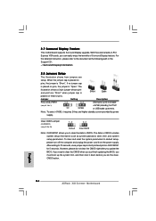
Then connect the white end of SATA power cable to the power connector of SATA power cable to the power connector on this motherboard. Each USB 2.0 header can securely store keys, digital certificates, passwords, and data. A TPM system also helps enhance ...ATA (SATA) Power Cable (Optional) connect to the SATA HDD power connector connect to the power supply Please connect the black end of the power supply. This connector allows you to receive stereo audio input from sound sources such as a CD-ROM, DVD-ROM, TV tuner card, or MPEG card. 26 ASRock X58 Extreme Motherboard English
Then connect the white end of SATA power cable to the power connector of SATA power cable to the power connector on this motherboard. Each USB 2.0 header can securely store keys, digital certificates, passwords, and data. A TPM system also helps enhance ...ATA (SATA) Power Cable (Optional) connect to the SATA HDD power connector connect to the power supply Please connect the black end of the power supply. This connector allows you to receive stereo audio input from sound sources such as a CD-ROM, DVD-ROM, TV tuner card, or MPEG card. 26 ASRock X58 Extreme Motherboard English
Quick Installation Guide
Page 28
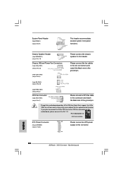
...CPU fan connector on this header. Chassis Speaker Header (4-pin SPEAKER 1) (see p.2 No. 19) Chassis, NB and Power Fan Connectors (4-pin CHA_FAN1) (see p.2 No. 23) (3-pin CHA_FAN2) (see p.2 No. 2) Please connect a CPU...ASRock X58 Extreme Motherboard Though this connector and match 2 1 the black wire to this connector. Pin 1-3 Connected 3-Pin Fan Installation ATX Power Connector (24-pin ATXPWR1) (see p.2 No. 9) This header accommodates several system front panel functions. System Panel Header (9-pin PANEL1) (see p.2, No. 8) 12 24 1 13 Please connect an ATX power supply...
...CPU fan connector on this header. Chassis Speaker Header (4-pin SPEAKER 1) (see p.2 No. 19) Chassis, NB and Power Fan Connectors (4-pin CHA_FAN1) (see p.2 No. 23) (3-pin CHA_FAN2) (see p.2 No. 2) Please connect a CPU...ASRock X58 Extreme Motherboard Though this connector and match 2 1 the black wire to this connector. Pin 1-3 Connected 3-Pin Fan Installation ATX Power Connector (24-pin ATXPWR1) (see p.2 No. 9) This header accommodates several system front panel functions. System Panel Header (9-pin PANEL1) (see p.2, No. 8) 12 24 1 13 Please connect an ATX power supply...
Quick Installation Guide
Page 29
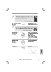
..., it can still work if you adopt a traditional 20-pin ATX power supply. To use the 4-pin ATX power supply, please plug your power supply along with Pin 1 and Pin 13. 20-Pin ATX Power Supply Installation 1 13 ATX 12V Power Connector 8 5 (8-pin ATX12V1) (see p.2 No. 30) card, allows the ... header, providing n (3-pin HDMI_SPDIF1) SPDIF audio output to HDMI VGA (see p.2 No. 3) 4 1 Please connect an ATX 12V power supply to this connector. This COM1 header supports a serial port module. English 29 ASRock X58 Extreme Motherboard Though this motherboard.
..., it can still work if you adopt a traditional 20-pin ATX power supply. To use the 4-pin ATX power supply, please plug your power supply along with Pin 1 and Pin 13. 20-Pin ATX Power Supply Installation 1 13 ATX 12V Power Connector 8 5 (8-pin ATX12V1) (see p.2 No. 30) card, allows the ... header, providing n (3-pin HDMI_SPDIF1) SPDIF audio output to HDMI VGA (see p.2 No. 3) 4 1 Please connect an ATX 12V power supply to this connector. This COM1 header supports a serial port module. English 29 ASRock X58 Extreme Motherboard Though this motherboard.

