
Quick Installation Guide
Page 5
...-pin DDR4 DIMM Slots (DDR4_A2, DDR4_B2) 8 ATX Power Connector (ATXPWR1) 9 USB 3.2 Gen1 Header (USB3_7_8) 10 Chassis / Waterpump Fan Connector (CHA_FAN1/WP) 11 AMD LED Fan USB Header (USB_5) 12 AMD FAN LED Header (AMD_FAN_LED1) 13 Front Panel Type C USB 3.2 Gen2 Header (F_USB31_TC_1) 14 Chassis / Waterpump Fan Connector (CHA_FAN4/WP) 15 SATA3 Connectors (SATA3_1_2) 16 SATA3 Connectors (SATA3_3_4) 17 SATA3 Connectors (SATA3_5_6) 18 SATA3 Connectors (SATA3_7_8) 19 Clear CMOS Button (CLRCBTN2) 20 System Panel Header (PANEL1) 21 Power Button (PWRBTN1) 22 Reset Button (RSTBTN1) 23 Clear CMOS Jumper...
...-pin DDR4 DIMM Slots (DDR4_A2, DDR4_B2) 8 ATX Power Connector (ATXPWR1) 9 USB 3.2 Gen1 Header (USB3_7_8) 10 Chassis / Waterpump Fan Connector (CHA_FAN1/WP) 11 AMD LED Fan USB Header (USB_5) 12 AMD FAN LED Header (AMD_FAN_LED1) 13 Front Panel Type C USB 3.2 Gen2 Header (F_USB31_TC_1) 14 Chassis / Waterpump Fan Connector (CHA_FAN4/WP) 15 SATA3 Connectors (SATA3_1_2) 16 SATA3 Connectors (SATA3_3_4) 17 SATA3 Connectors (SATA3_5_6) 18 SATA3 Connectors (SATA3_7_8) 19 Clear CMOS Button (CLRCBTN2) 20 System Panel Header (PANEL1) 21 Power Button (PWRBTN1) 22 Reset Button (RSTBTN1) 23 Clear CMOS Jumper...

Quick Installation Guide
Page 13
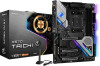
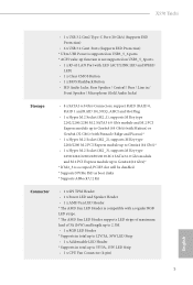
...Protection) • 6 x USB 3.2 Gen1 Ports (Supports ESD Protection) * Ultra USB Power is supported on USB3_5_6 ports. * ACPI wake-up function is not supported on USB3_5_6ports. • 1 x RJ-45 LAN Port with LED (ACT/LINK LED and SPEED LED) • 1 x Clear CMOS Button • 1 x BIOS Flashback Button • HD Audio Jacks: Rear Speaker / Central / Bass / Line in / Front Speaker / Microphone (Gold Audio Jacks) Storage • 8 x SATA3 6.0 Gb/s Connectors, support RAID (RAID 0, RAID 1 and RAID 10), NCQ, AHCI and Hot Plug • 1 x Hyper M.2 Socket (M2_1), supports M Key type 2242/2260...
...Protection) • 6 x USB 3.2 Gen1 Ports (Supports ESD Protection) * Ultra USB Power is supported on USB3_5_6 ports. * ACPI wake-up function is not supported on USB3_5_6ports. • 1 x RJ-45 LAN Port with LED (ACT/LINK LED and SPEED LED) • 1 x Clear CMOS Button • 1 x BIOS Flashback Button • HD Audio Jacks: Rear Speaker / Central / Bass / Line in / Front Speaker / Microphone (Gold Audio Jacks) Storage • 8 x SATA3 6.0 Gb/s Connectors, support RAID (RAID 0, RAID 1 and RAID 10), NCQ, AHCI and Hot Plug • 1 x Hyper M.2 Socket (M2_1), supports M Key type 2242/2260...
Quick Installation Guide
Page 14
... Panel Audio Connector (15μ Gold Audio Connector) • 1 x AMD LED Fan USB Header • 1 x Thunderbolt AIC Connector (5-pin) (Supports ASRock Thunderbolt AIC Card only) • 2 x USB 2.0 Headers (Support 4 USB 2.0 ports) (Supports ESD Protection) • 1 x USB 3.2 Gen1 Header (Supports 2 USB 3.2 Gen1 ports) (Supports ESD Protection) • 1 x Front Panel Type C USB 3.2 Gen2 Header (Supports ESD Protection) • 1 x Dr. Debug with LED • 1 x Power Button with LED • 1 x Reset Button with LED • 1 x Clear CMOS Button • AMI UEFI Legal BIOS with GUI support...
... Panel Audio Connector (15μ Gold Audio Connector) • 1 x AMD LED Fan USB Header • 1 x Thunderbolt AIC Connector (5-pin) (Supports ASRock Thunderbolt AIC Card only) • 2 x USB 2.0 Headers (Support 4 USB 2.0 ports) (Supports ESD Protection) • 1 x USB 3.2 Gen1 Header (Supports 2 USB 3.2 Gen1 ports) (Supports ESD Protection) • 1 x Front Panel Type C USB 3.2 Gen2 Header (Supports ESD Protection) • 1 x Dr. Debug with LED • 1 x Power Button with LED • 1 x Reset Button with LED • 1 x Clear CMOS Button • AMI UEFI Legal BIOS with GUI support...

Quick Installation Guide
Page 32
... card and make sure that the power supply is switched off or the power cord is used for PCI Express x1 lane width cards. PCIE5 (PCIe 4.0 x16 slot) is used for PCI Express x1 lane width cards. PCIe Slot Configurations Ryzen Series CPUs (Matisse) Ryzen Series CPUs (Pinnacle Ridge) PCIE1 Gen4x8 Gen3x8 PCIE3 Gen4x8 Gen3x8 PCIE5 Gen4x4 Gen4x4 Gen3x8 N/A N/A Ryzen Series CPUs (Picasso) N/A N/A Gen4x4 For a better thermal environment, please connect a chassis fan to the motherboard's chassis fan connector...
... card and make sure that the power supply is switched off or the power cord is used for PCI Express x1 lane width cards. PCIE5 (PCIe 4.0 x16 slot) is used for PCI Express x1 lane width cards. PCIe Slot Configurations Ryzen Series CPUs (Matisse) Ryzen Series CPUs (Pinnacle Ridge) PCIE1 Gen4x8 Gen3x8 PCIE3 Gen4x8 Gen3x8 PCIE5 Gen4x4 Gen4x4 Gen3x8 N/A N/A Ryzen Series CPUs (Picasso) N/A N/A Gen4x4 For a better thermal environment, please connect a chassis fan to the motherboard's chassis fan connector...

Quick Installation Guide
Page 35
... AMD SR3 Heatsink. This USB 3.2 Gen1 header can support two ports. SATA3_7 SATA3_6 SATA3_4 SATA3_2 SATA3_8 SATA3_5 SATA3_3 SATA3_1 AMD LED Fan USB Header (4-pin USB_5) (see p.1, No. 11) USB 2.0 Headers (9-pin USB_1_2) (see p.1, No. 24) (9-pin USB_3_4) (see p.1, No. 18) SPEAKER DUMMY DUMMY +5V 1 PLED+ PLED+ PLED- These eight SATA3 connectors support SATA data cables for connecting the USB connector on this header. Each USB 2.0 header can support two ports. 32 English Power LED and Speaker Header (7-pin SPK_PLED1) (see p.1, No. 26) Serial ATA3 Connectors...
... AMD SR3 Heatsink. This USB 3.2 Gen1 header can support two ports. SATA3_7 SATA3_6 SATA3_4 SATA3_2 SATA3_8 SATA3_5 SATA3_3 SATA3_1 AMD LED Fan USB Header (4-pin USB_5) (see p.1, No. 11) USB 2.0 Headers (9-pin USB_1_2) (see p.1, No. 24) (9-pin USB_3_4) (see p.1, No. 18) SPEAKER DUMMY DUMMY +5V 1 PLED+ PLED+ PLED- These eight SATA3 connectors support SATA data cables for connecting the USB connector on this header. Each USB 2.0 header can support two ports. 32 English Power LED and Speaker Header (7-pin SPK_PLED1) (see p.1, No. 26) Serial ATA3 Connectors...
Quick Installation Guide
Page 41
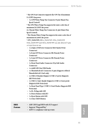
... LED starts to update BIOS without CPU. ASRock BIOS Flashback feature allows you plug the USB drive to flash the BIOS. English USB BIOS Flashback port 38 To use the USB BIOS Flashback function, Please follow the steps below. 1. Plug the 24 pin power connector to the USB BIOS Flashback port. 7. Press the BIOS Flashback Switch for about three seconds. Extract BIOS file from ASRock's website : http://www.asrock.com. 2. Then plug your USB drive to the motherboard. BIOS Flashback Button (BIOS_FB1) (see p.3, No. 17) BIOS Flashback Switch allows users...
... LED starts to update BIOS without CPU. ASRock BIOS Flashback feature allows you plug the USB drive to flash the BIOS. English USB BIOS Flashback port 38 To use the USB BIOS Flashback function, Please follow the steps below. 1. Plug the 24 pin power connector to the USB BIOS Flashback port. 7. Press the BIOS Flashback Switch for about three seconds. Extract BIOS file from ASRock's website : http://www.asrock.com. 2. Then plug your USB drive to the motherboard. BIOS Flashback Button (BIOS_FB1) (see p.3, No. 17) BIOS Flashback Switch allows users...

User Manual
Page 5
...1 1.1 Package Contents 1 1.2 Specifications 2 1.3 Motherboard Layout 8 1.4 I/O Panel 10 1.6 WiFi-802.11ax Module and ASRock WiFi 2.4/5 GHz Antenna 13 Chapter 2 Installation 14 2.1 Installing the CPU 15 2.2 Installing the CPU Fan and Heatsink 17 2.3 Installing Memory Modules (DIMM) 26 2.4 Expansion Slots (PCI Express Slots) 29 2.5 Jumpers Setup 30 2.6 Onboard Headers and Connectors 31 2.7 Smart Switches 37 2.8 Dr. Debug 39 2.9 SLITM and Quad SLITM Operation Guide 45 2.9.1 Installing Two SLITM-Ready Graphics Cards 45 2.9.2 Driver Installation and Setup 47 2.10...
...1 1.1 Package Contents 1 1.2 Specifications 2 1.3 Motherboard Layout 8 1.4 I/O Panel 10 1.6 WiFi-802.11ax Module and ASRock WiFi 2.4/5 GHz Antenna 13 Chapter 2 Installation 14 2.1 Installing the CPU 15 2.2 Installing the CPU Fan and Heatsink 17 2.3 Installing Memory Modules (DIMM) 26 2.4 Expansion Slots (PCI Express Slots) 29 2.5 Jumpers Setup 30 2.6 Onboard Headers and Connectors 31 2.7 Smart Switches 37 2.8 Dr. Debug 39 2.9 SLITM and Quad SLITM Operation Guide 45 2.9.1 Installing Two SLITM-Ready Graphics Cards 45 2.9.2 Driver Installation and Setup 47 2.10...
User Manual
Page 8
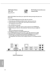
... change without further notice. X570 Taichi Chapter 1 Introduction Thank you for M.2 Sockets (Optional) 1 English Chapter 4 contains the configuration guide of the software and utilities. In case any modifications of this documentation occur, the updated version will be available on ASRock's website as well. ASRock website http://www.asrock.com. 1.1 Package Contents • ASRock X570 Taichi Motherboard (ATX Form Factor) • ASRock X570 Taichi Quick Installation Guide • ASRock X570 Taichi Support CD • 4 x Serial ATA (SATA) Data Cables (Optional) • 1 x ASRock...
... change without further notice. X570 Taichi Chapter 1 Introduction Thank you for M.2 Sockets (Optional) 1 English Chapter 4 contains the configuration guide of the software and utilities. In case any modifications of this documentation occur, the updated version will be available on ASRock's website as well. ASRock website http://www.asrock.com. 1.1 Package Contents • ASRock X570 Taichi Motherboard (ATX Form Factor) • ASRock X570 Taichi Quick Installation Guide • ASRock X570 Taichi Support CD • 4 x Serial ATA (SATA) Data Cables (Optional) • 1 x ASRock...
User Manual
Page 12
...Protection) • 6 x USB 3.2 Gen1 Ports (Supports ESD Protection) * Ultra USB Power is supported on USB3_5_6 ports. * ACPI wake-up function is not supported on USB3_5_6ports. • 1 x RJ-45 LAN Port with LED (ACT/LINK LED and SPEED LED) • 1 x Clear CMOS Button • 1 x BIOS Flashback Button • HD Audio Jacks: Rear Speaker / Central / Bass / Line in / Front Speaker / Microphone (Gold Audio Jacks) Storage • 8 x SATA3 6.0 Gb/s Connectors, support RAID (RAID 0, RAID 1 and RAID 10), NCQ, AHCI and Hot Plug • 1 x Hyper M.2 Socket (M2_1), supports M Key type 2242/2260...
...Protection) • 6 x USB 3.2 Gen1 Ports (Supports ESD Protection) * Ultra USB Power is supported on USB3_5_6 ports. * ACPI wake-up function is not supported on USB3_5_6ports. • 1 x RJ-45 LAN Port with LED (ACT/LINK LED and SPEED LED) • 1 x Clear CMOS Button • 1 x BIOS Flashback Button • HD Audio Jacks: Rear Speaker / Central / Bass / Line in / Front Speaker / Microphone (Gold Audio Jacks) Storage • 8 x SATA3 6.0 Gb/s Connectors, support RAID (RAID 0, RAID 1 and RAID 10), NCQ, AHCI and Hot Plug • 1 x Hyper M.2 Socket (M2_1), supports M Key type 2242/2260...

User Manual
Page 13
... Panel Audio Connector (15μ Gold Audio Connector) • 1 x AMD LED Fan USB Header • 1 x Thunderbolt AIC Connector (5-pin) (Supports ASRock Thunderbolt AIC Card only) • 2 x USB 2.0 Headers (Support 4 USB 2.0 ports) (Supports ESD Protection) • 1 x USB 3.2 Gen1 Header (Supports 2 USB 3.2 Gen1 ports) (Supports ESD Protection) • 1 x Front Panel Type C USB 3.2 Gen2 Header (Supports ESD Protection) • 1 x Dr. Debug with LED • 1 x Power Button with LED • 1 x Reset Button with LED • 1 x Clear CMOS Button • AMI UEFI Legal BIOS with GUI support...
... Panel Audio Connector (15μ Gold Audio Connector) • 1 x AMD LED Fan USB Header • 1 x Thunderbolt AIC Connector (5-pin) (Supports ASRock Thunderbolt AIC Card only) • 2 x USB 2.0 Headers (Support 4 USB 2.0 ports) (Supports ESD Protection) • 1 x USB 3.2 Gen1 Header (Supports 2 USB 3.2 Gen1 ports) (Supports ESD Protection) • 1 x Front Panel Type C USB 3.2 Gen2 Header (Supports ESD Protection) • 1 x Dr. Debug with LED • 1 x Power Button with LED • 1 x Reset Button with LED • 1 x Clear CMOS Button • AMI UEFI Legal BIOS with GUI support...

User Manual
Page 16
...) 16 SATA3 Connectors (SATA3_3_4) 17 SATA3 Connectors (SATA3_5_6) 18 SATA3 Connectors (SATA3_7_8) 19 Clear CMOS Button (CLRCBTN2) 20 System Panel Header (PANEL1) 21 Power Button (PWRBTN1) 22 Reset Button (RSTBTN1) 23 Clear CMOS Jumper (CLRCMOS1) 24 USB 2.0 Header (USB_1_2) 25 USB 2.0 Header (USB_3_4) 26 Power LED and Speaker Header (SPK_PLED1) 27 Chassis/Water Pump Fan Connector (CHA_FAN2/WP) 28 RGB LED Header (RGB_HEADER1) 29 Addressable LED Header (ADDR_LED1) 30 Thunderbolt AIC Header (TB1) 31 Front Panel Audio Header (HD_AUDIO1) 32 SPI TPM Header (SPI_TPM_J1) X570 Taichi 9 English
...) 16 SATA3 Connectors (SATA3_3_4) 17 SATA3 Connectors (SATA3_5_6) 18 SATA3 Connectors (SATA3_7_8) 19 Clear CMOS Button (CLRCBTN2) 20 System Panel Header (PANEL1) 21 Power Button (PWRBTN1) 22 Reset Button (RSTBTN1) 23 Clear CMOS Jumper (CLRCMOS1) 24 USB 2.0 Header (USB_1_2) 25 USB 2.0 Header (USB_3_4) 26 Power LED and Speaker Header (SPK_PLED1) 27 Chassis/Water Pump Fan Connector (CHA_FAN2/WP) 28 RGB LED Header (RGB_HEADER1) 29 Addressable LED Header (ADDR_LED1) 30 Thunderbolt AIC Header (TB1) 31 Front Panel Audio Header (HD_AUDIO1) 32 SPI TPM Header (SPI_TPM_J1) X570 Taichi 9 English

User Manual
Page 36
... disabled. PCIe Slot Configurations Ryzen Series CPUs (Matisse) Ryzen Series CPUs (Pinnacle Ridge) PCIE1 Gen4x8 Gen3x8 PCIE3 Gen4x8 Gen3x8 PCIE5 Gen4x4 Gen4x4 Gen3x8 N/A N/A Ryzen Series CPUs (Picasso) N/A N/A Gen4x4 For a better thermal environment, please connect a chassis fan to the motherboard's chassis fan connector (CHA_FAN1/WP, CHA_FAN2/WP , CHA_FAN3/WP or CHA_FAN4/WP ) when using multiple graphics cards. PCIE5 (PCIe 4.0 x16 slot) is used for PCI Express x4 lane width graphics cards. * If PCIE5 slot is used for PCI Express...
... disabled. PCIe Slot Configurations Ryzen Series CPUs (Matisse) Ryzen Series CPUs (Pinnacle Ridge) PCIE1 Gen4x8 Gen3x8 PCIE3 Gen4x8 Gen3x8 PCIE5 Gen4x4 Gen4x4 Gen3x8 N/A N/A Ryzen Series CPUs (Picasso) N/A N/A Gen4x4 For a better thermal environment, please connect a chassis fan to the motherboard's chassis fan connector (CHA_FAN1/WP, CHA_FAN2/WP , CHA_FAN3/WP or CHA_FAN4/WP ) when using multiple graphics cards. PCIE5 (PCIe 4.0 x16 slot) is used for PCI Express x4 lane width graphics cards. * If PCIE5 slot is used for PCI Express...

User Manual
Page 39
... 1 There is used for internal storage devices with up to this motherboard. Each USB 2.0 header can support two ports. 32 English P+ USB_PWR This header is a header on this motherboard. USB 3.2 Gen1 Header (19-pin USB3_7_8) (see p.8, No. 25) 1 GND P- These eight SATA3 connectors support SATA data cables for connecting the USB connector on this header. USB_PWR PP+ GND DUMMY 1 GND P+ PUSB_PWR There are two headers on the AMD SR3 Heatsink. This USB 3.2 Gen1 header can support two ports. Power LED and Speaker Header (7-pin SPK_PLED1...
... 1 There is used for internal storage devices with up to this motherboard. Each USB 2.0 header can support two ports. 32 English P+ USB_PWR This header is a header on this motherboard. USB 3.2 Gen1 Header (19-pin USB3_7_8) (see p.8, No. 25) 1 GND P- These eight SATA3 connectors support SATA data cables for connecting the USB connector on this header. USB_PWR PP+ GND DUMMY 1 GND P+ PUSB_PWR There are two headers on the AMD SR3 Heatsink. This USB 3.2 Gen1 header can support two ports. Power LED and Speaker Header (7-pin SPK_PLED1...

User Manual
Page 45
...) BIOS Flashback Switch allows users to the motherboard. ASRock BIOS Flashback feature allows you plug the USB drive to update BIOS without CPU. To use the USB BIOS Flashback function, Please follow the steps below. 1. Plug the 24 pin power connector to flash the BIOS. Press the BIOS Flashback Switch for about three seconds. Then the LED starts to the root directory of your USB flash drive must be FAT32. 3. Wait until the LED stops blinking, indicating that BIOS flashing has...
...) BIOS Flashback Switch allows users to the motherboard. ASRock BIOS Flashback feature allows you plug the USB drive to update BIOS without CPU. To use the USB BIOS Flashback function, Please follow the steps below. 1. Plug the 24 pin power connector to flash the BIOS. Press the BIOS Flashback Switch for about three seconds. Then the LED starts to the root directory of your USB flash drive must be FAT32. 3. Wait until the LED stops blinking, indicating that BIOS flashing has...

User Manual
Page 55
... Operation Guide This motherboard supports CrossFireXTM, 3-way CrossFireXTM and Quad CrossFireXTM that allows you to install up to use identical CrossFireXTM-ready graphics cards that the cards are AMD certified. 2. Download the drivers from the AMD's website: www.amd.com 3. Make sure that are properly seated on the top of the graphics cards. (The CrossFire Bridge is recommended to three identical PCI Express x16 graphics cards. 1. You should only use a AMD...
... Operation Guide This motherboard supports CrossFireXTM, 3-way CrossFireXTM and Quad CrossFireXTM that allows you to install up to use identical CrossFireXTM-ready graphics cards that the cards are AMD certified. 2. Download the drivers from the AMD's website: www.amd.com 3. Make sure that are properly seated on the top of the graphics cards. (The CrossFire Bridge is recommended to three identical PCI Express x16 graphics cards. 1. You should only use a AMD...
User Manual
Page 58
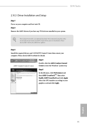
... computer and boot into OS. Please check AMD's website for AMD driver updates. Step 2 Remove the AMD drivers if you have any previously installed Catalyst drivers prior to installation. X570 Taichi 2.10.3 Driver Installation and Setup Step 1 Power on your computer. Step 5 In the left pane, click Performance and then AMD CrossFireXTM. The Catalyst Uninstaller is an optional download. Select the GPU number according to uninstall any VGA drivers installed in the Windows®...
... computer and boot into OS. Please check AMD's website for AMD driver updates. Step 2 Remove the AMD drivers if you have any previously installed Catalyst drivers prior to installation. X570 Taichi 2.10.3 Driver Installation and Setup Step 1 Power on your computer. Step 5 In the left pane, click Performance and then AMD CrossFireXTM. The Catalyst Uninstaller is an optional download. Select the GPU number according to uninstall any VGA drivers installed in the Windows®...
User Manual
Page 68
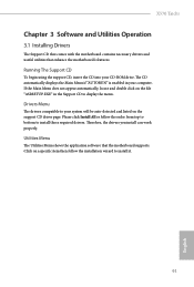
... motherboard contains necessary drivers and useful utilities that the motherboard supports. If the Main Menu does not appear automatically, locate and double click on the file "ASRSETUP.EXE" in your computer. Utilities Menu The Utilities Menu shows the application software that enhance the motherboard's features. Therefore, the drivers you install can work properly. Drivers Menu The drivers compatible to display the menu. The CD automatically displays the Main Menu if "AUTORUN" is enabled in the Support CD to your CD-ROM drive...
... motherboard contains necessary drivers and useful utilities that the motherboard supports. If the Main Menu does not appear automatically, locate and double click on the file "ASRSETUP.EXE" in your computer. Utilities Menu The Utilities Menu shows the application software that enhance the motherboard's features. Therefore, the drivers you install can work properly. Drivers Menu The drivers compatible to display the menu. The CD automatically displays the Main Menu if "AUTORUN" is enabled in the Support CD to your CD-ROM drive...

User Manual
Page 85
... installed. SMT Mode This item can be enabled to alter the frequency for the GFX clock frequency. DRAM Timing Configuration Load XMP Setting Load XMP settings to support memory and Infinity Fabric overclocking. Infinity Fabric Frequency and Dividers Set Infinity Fabric Frequency and Dividers (FCLK). GFX Core Voltage (Only for the GFX Core Voltage. *The adjustable range is disabled. DRAM Frequency If [Auto] is depending on the CPU's capability. Final result is selected, the motherboard will be set to [Manual...
... installed. SMT Mode This item can be enabled to alter the frequency for the GFX clock frequency. DRAM Timing Configuration Load XMP Setting Load XMP settings to support memory and Infinity Fabric overclocking. Infinity Fabric Frequency and Dividers Set Infinity Fabric Frequency and Dividers (FCLK). GFX Core Voltage (Only for the GFX Core Voltage. *The adjustable range is disabled. DRAM Frequency If [Auto] is depending on the CPU's capability. Final result is selected, the motherboard will be set to [Manual...
User Manual
Page 99
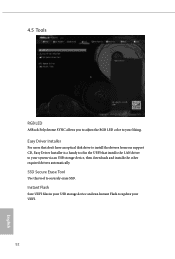
4.5 Tools RGB LED ASRock Polychrome SYNC allows you to adjust the RGB LED color to your UEFI. 92 English SSD Secure Erase Tool Use this tool to update your liking. Instant Flash Save UEFI files in the UEFI that installs the LAN driver to your system via an USB storage device, then downloads and installs the other required drivers automatically. Easy Driver Installer For users that don't have an optical disk drive to install the drivers from our support CD, Easy Driver Installer is a handy tool in your USB storage device and run Instant Flash to securely erase SSD.
4.5 Tools RGB LED ASRock Polychrome SYNC allows you to adjust the RGB LED color to your UEFI. 92 English SSD Secure Erase Tool Use this tool to update your liking. Instant Flash Save UEFI files in the UEFI that installs the LAN driver to your system via an USB storage device, then downloads and installs the other required drivers automatically. Easy Driver Installer For users that don't have an optical disk drive to install the drivers from our support CD, Easy Driver Installer is a handy tool in your USB storage device and run Instant Flash to securely erase SSD.
RAID Installation Guide
Page 15
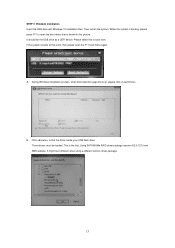
... open the F11 boot menu again. Three drivers must be loaded. Using SATA/NVMe RAID driver package (version 9.2.0.127) from . B. Then restart the system. If the system restarts at this to find the driver inside your USB flash drive. It should list the USB drive as a UEFI device. While this picture. Click to boot from AMD website. STEP 3: Windows installation Insert the USB drive with Windows 10 installation files. It might look different when using a different version driver package. 15...
... open the F11 boot menu again. Three drivers must be loaded. Using SATA/NVMe RAID driver package (version 9.2.0.127) from . B. Then restart the system. If the system restarts at this to find the driver inside your USB flash drive. It should list the USB drive as a UEFI device. While this picture. Click to boot from AMD website. STEP 3: Windows installation Insert the USB drive with Windows 10 installation files. It might look different when using a different version driver package. 15...


