Quick Installation Guide
Page 4
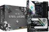
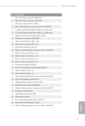
...-pin DDR4 DIMM Slots (DDR4_A2, DDR4_B2) 7 AMD FAN LED Header (AMD_FAN_LED1) 8 ATX Power Connector (ATXPWR1) 9 USB 3.2 Gen1 Header (USB3_9_10) 10 USB 3.2 Gen1 Header (USB3_7_8) 11 SPI TPM Header (SPI_TPM_J1) 12 Chassis / Waterpump Fan Connector (CHA_FAN4/WP) 13 SATA3 Connectors (SATA3_1_2) 14 SATA3 Connectors (SATA3_3_4) 15 SATA3 Connectors (SATA3_5_6) 16 SATA3 Connectors (SATA3_7_8) 17 System Panel Header (PANEL1) 18 Power LED and Speaker Header (SPK_PLED1) 19 USB 2.0 Header (USB_3_4) 20 USB 2.0 Header (USB_1_2) 21 Chassis/Water Pump Fan Connector (CHA_FAN3/WP) 22 Clear CMOS Jumper (CLRCMOS1...
...-pin DDR4 DIMM Slots (DDR4_A2, DDR4_B2) 7 AMD FAN LED Header (AMD_FAN_LED1) 8 ATX Power Connector (ATXPWR1) 9 USB 3.2 Gen1 Header (USB3_9_10) 10 USB 3.2 Gen1 Header (USB3_7_8) 11 SPI TPM Header (SPI_TPM_J1) 12 Chassis / Waterpump Fan Connector (CHA_FAN4/WP) 13 SATA3 Connectors (SATA3_1_2) 14 SATA3 Connectors (SATA3_3_4) 15 SATA3 Connectors (SATA3_5_6) 16 SATA3 Connectors (SATA3_7_8) 17 System Panel Header (PANEL1) 18 Power LED and Speaker Header (SPK_PLED1) 19 USB 2.0 Header (USB_3_4) 20 USB 2.0 Header (USB_1_2) 21 Chassis/Water Pump Fan Connector (CHA_FAN3/WP) 22 Clear CMOS Jumper (CLRCMOS1...

Quick Installation Guide
Page 9
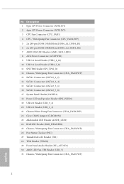
dual at x16 (PCIE1); X570 Steel Legend 1.2 Specifications Platform • ATX Form Factor • 2oz Copper PCB CPU • Supports AMD AM4 socket Ryzen™ 2000 and 3000 series processors • Intersil Digital PWM • 10 Power Phase design Chipset • AMD X570 Memory • Dual Channel DDR4 Memory Technology • 4 x DDR4 DIMM Slots • AMD Ryzen series CPUs (Matisse) support DDR4 4666+ (OC)/4400(OC)/4300(OC)/4266(OC)/4200(OC)/4133(OC)/ 3466(OC...
dual at x16 (PCIE1); X570 Steel Legend 1.2 Specifications Platform • ATX Form Factor • 2oz Copper PCB CPU • Supports AMD AM4 socket Ryzen™ 2000 and 3000 series processors • Intersil Digital PWM • 10 Power Phase design Chipset • AMD X570 Memory • Dual Channel DDR4 Memory Technology • 4 x DDR4 DIMM Slots • AMD Ryzen series CPUs (Matisse) support DDR4 4666+ (OC)/4400(OC)/4300(OC)/4266(OC)/4200(OC)/4133(OC)/ 3466(OC...
Quick Installation Guide
Page 10
... (High Bit Rate Audio) with HDMI 2.0Ports (Compliant HDMI monitor is used to 4K x 2K (4096x2160) @ 30Hz • Supports DisplayPort 1.4 with HDMI 2.0and DisplayPort 1.4 Ports • Supports Microsoft PlayReady® English 8 resolution up to 16GB. * The Max shared memory 16GB requires 32GB system memory installed. • Dual graphics output: support HDMI and DisplayPort 1.4 ports by CPU • DirectX 12, Pixel Shader 5.0 • Shared memory default 2GB. Graphics AMD Ryzen series CPUs (Pinnacle Ridge) • 2 x PCI Express 3.0 x16 Slots (single...
... (High Bit Rate Audio) with HDMI 2.0Ports (Compliant HDMI monitor is used to 4K x 2K (4096x2160) @ 30Hz • Supports DisplayPort 1.4 with HDMI 2.0and DisplayPort 1.4 Ports • Supports Microsoft PlayReady® English 8 resolution up to 16GB. * The Max shared memory 16GB requires 32GB system memory installed. • Dual graphics output: support HDMI and DisplayPort 1.4 ports by CPU • DirectX 12, Pixel Shader 5.0 • Shared memory default 2GB. Graphics AMD Ryzen series CPUs (Pinnacle Ridge) • 2 x PCI Express 3.0 x16 Slots (single...

Quick Installation Guide
Page 13
...Gold Audio Connector) • 1 x AMD LED Fan USB Header • 1 x Thunderbolt AIC Connector (5-pin) (Supports ASRock Thunderbolt AIC Card only) • 2 x USB 2.0 Headers (Support 4 USB 2.0 ports) (Supports ESD Protection) • 2 x USB 3.2 Gen1 Headers (Support 4 USB 3.2 Gen1 ports) (Supports ESD Protection) • AMI UEFI Legal BIOS with GUI support • Supports "Plug and Play" • ACPI 5.1 compliance wake up events • Supports jumperfree • SMBIOS 2.3 support • CPU, CPU VDDCR_SOC, DRAM, VPPM, PREM VDD_ CLDO, PERM VDDCR_SOC, +1.8V, VDDP Voltage Multiadjustment...
...Gold Audio Connector) • 1 x AMD LED Fan USB Header • 1 x Thunderbolt AIC Connector (5-pin) (Supports ASRock Thunderbolt AIC Card only) • 2 x USB 2.0 Headers (Support 4 USB 2.0 ports) (Supports ESD Protection) • 2 x USB 3.2 Gen1 Headers (Support 4 USB 3.2 Gen1 ports) (Supports ESD Protection) • AMI UEFI Legal BIOS with GUI support • Supports "Plug and Play" • ACPI 5.1 compliance wake up events • Supports jumperfree • SMBIOS 2.3 support • CPU, CPU VDDCR_SOC, DRAM, VPPM, PREM VDD_ CLDO, PERM VDDCR_SOC, +1.8V, VDDP Voltage Multiadjustment...
Quick Installation Guide
Page 30
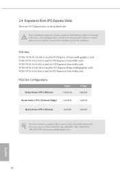
... power cord is used for the card before you start the installation. PCIE4 (PCIe 4.0 x16 slot) is unplugged. PCIE5 (PCIe 4.0 x1 slot) is used for PCI Express x16 lane width graphics cards. PCIe slots: PCIE1 (PCIe 4.0 x16 slot) is used for PCI Express x1 lane width cards. PCIe Slot Configurations Ryzen Series CPUs (Matisse) PCIE1 Gen4x16 Ryzen Series CPUs (Pinnacle Ridge) Gen3x16 PCIE4 Gen4x4 Gen3x4 Ryzen Series CPUs (Picasso) Gen3x8 Gen3x4 For a better thermal environment, please connect a chassis fan to the motherboard's chassis fan connector...
... power cord is used for the card before you start the installation. PCIE4 (PCIe 4.0 x16 slot) is unplugged. PCIE5 (PCIe 4.0 x1 slot) is used for PCI Express x16 lane width graphics cards. PCIe slots: PCIE1 (PCIe 4.0 x16 slot) is used for PCI Express x1 lane width cards. PCIe Slot Configurations Ryzen Series CPUs (Matisse) PCIE1 Gen4x16 Ryzen Series CPUs (Pinnacle Ridge) Gen3x16 PCIE4 Gen4x4 Gen3x4 Ryzen Series CPUs (Picasso) Gen3x8 Gen3x4 For a better thermal environment, please connect a chassis fan to the motherboard's chassis fan connector...

Quick Installation Guide
Page 33
Please connect the chassis power LED and the chassis speaker to 6.0 Gb/s data transfer rate. USB_PWR PP+ GND DUMMY 1 GND P+ PUSB_PWR There are two headers on this motherboard. Each USB 2.0 header can support two ports. 31 English Each USB 3.2 Gen1 header can support two ports. X570 Steel Legend Power LED and Speaker Header (7-pin SPK_PLED1) (see p.1, No. 18) Serial ATA3 Connectors (SATA3_1_2: see p.1, No. 13) (SATA3_3_4: see p.1, No. 14) (SATA3_5_6: see p.1, No. 15) (SATA3_7_8: see p.1, No. 19...
Please connect the chassis power LED and the chassis speaker to 6.0 Gb/s data transfer rate. USB_PWR PP+ GND DUMMY 1 GND P+ PUSB_PWR There are two headers on this motherboard. Each USB 2.0 header can support two ports. 31 English Each USB 3.2 Gen1 header can support two ports. X570 Steel Legend Power LED and Speaker Header (7-pin SPK_PLED1) (see p.1, No. 18) Serial ATA3 Connectors (SATA3_1_2: see p.1, No. 13) (SATA3_3_4: see p.1, No. 14) (SATA3_5_6: see p.1, No. 15) (SATA3_7_8: see p.1, No. 19...

Quick Installation Guide
Page 35
... a 4-Pin CPU fan (Quiet Fan) connector. To use a 4 1 4-pin ATX power supply, please plug it along Pin 1 and Pin 5. *Warning: Please make sure that the power cable connected is for the CPU and not the graphics card. Do not plug the PCIe power cable to Pin 1-3. If you plan to connect a 3-Pin CPU water cooler fan, please connect it to Pin 1-3. X570 Steel Legend CPU Fan Connector (4-pin CPU_FAN1) (see p.1, No. 4) FAN_SPEED_CONTROL FAN_SPEED FAN_VOLTAGE GND 4 This motherboard 3 provides a 4-Pin water 2 1 cooling CPU fan connector. ATX 12V Power Connector (8-pin...
... a 4-Pin CPU fan (Quiet Fan) connector. To use a 4 1 4-pin ATX power supply, please plug it along Pin 1 and Pin 5. *Warning: Please make sure that the power cable connected is for the CPU and not the graphics card. Do not plug the PCIe power cable to Pin 1-3. If you plan to connect a 3-Pin CPU water cooler fan, please connect it to Pin 1-3. X570 Steel Legend CPU Fan Connector (4-pin CPU_FAN1) (see p.1, No. 4) FAN_SPEED_CONTROL FAN_SPEED FAN_VOLTAGE GND 4 This motherboard 3 provides a 4-Pin water 2 1 cooling CPU fan connector. ATX 12V Power Connector (8-pin...
User Manual
Page 4
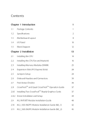
... Contents 1 1.2 Specifications 2 1.3 Motherboard Layout 8 1.4 I/O Panel 10 1.5 Block Diagram 12 Chapter 2 Installation 13 2.1 Installing the CPU 14 2.2 Installing the CPU Fan and Heatsink 16 2.3 Installing Memory Modules (DIMM) 25 2.4 Expansion Slots (PCI Express Slots) 28 2.5 Jumpers Setup 29 2.6 Onboard Headers and Connectors 30 2.7 Post Status Checker 36 2.8 CrossFireXTM and Quad CrossFireXTM Operation Guide 37 2.8.1 Installing Two CrossFireXTM-Ready Graphics Cards 37 2.8.2 Driver Installation and Setup 39 2.9 M.2 WiFi/BT Module Installation Guide 40 2.10...
... Contents 1 1.2 Specifications 2 1.3 Motherboard Layout 8 1.4 I/O Panel 10 1.5 Block Diagram 12 Chapter 2 Installation 13 2.1 Installing the CPU 14 2.2 Installing the CPU Fan and Heatsink 16 2.3 Installing Memory Modules (DIMM) 25 2.4 Expansion Slots (PCI Express Slots) 28 2.5 Jumpers Setup 29 2.6 Onboard Headers and Connectors 30 2.7 Post Status Checker 36 2.8 CrossFireXTM and Quad CrossFireXTM Operation Guide 37 2.8.1 Installing Two CrossFireXTM-Ready Graphics Cards 37 2.8.2 Driver Installation and Setup 39 2.9 M.2 WiFi/BT Module Installation Guide 40 2.10...
User Manual
Page 7
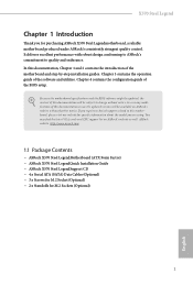
...and the BIOS software might be subject to change without further notice. Chapter 4 contains the configuration guide of the software and utilities. If you require technical support related to quality and endurance. X570 Steel Legend Chapter 1 Introduction Thank you are using. ASRock website http://www.asrock.com. 1.1 Package Contents • ASRock X570 Steel LegendMotherboard (ATX Form Factor) • ASRock X570 Steel LegendQuick Installation Guide • ASRock X570 Steel LegendSupport CD • 4 x Serial ATA (SATA) Data Cables (Optional) • 3 x Screws for M.2 Socket (Optional...
...and the BIOS software might be subject to change without further notice. Chapter 4 contains the configuration guide of the software and utilities. If you require technical support related to quality and endurance. X570 Steel Legend Chapter 1 Introduction Thank you are using. ASRock website http://www.asrock.com. 1.1 Package Contents • ASRock X570 Steel LegendMotherboard (ATX Form Factor) • ASRock X570 Steel LegendQuick Installation Guide • ASRock X570 Steel LegendSupport CD • 4 x Serial ATA (SATA) Data Cables (Optional) • 3 x Screws for M.2 Socket (Optional...

User Manual
Page 11
X570 Steel Legend Storage • 8 x SATA3 6.0 Gb/s Connectors, support RAID (RAID 0, RAID 1 and RAID 10), NCQ, AHCI and Hot Plug • 1 x Hyper M.2 Socket (M2_1), supports M Key type 2230/2242/2260/2280 M.2 PCI Express module up to Gen4x4 (64 Gb/s) (with Matisse) or Gen3x4 (32 Gb/s) (with Pinnacle Ridge and Picasso)* • 1 x Hyper M.2 Socket (M2_2), supports M Key type 2230/2242/2260/2280/22110 M.2 SATA3 6.0 Gb/s module and M.2 PCI Express module up to Gen4x4 (64 Gb/s)* * Supports NVMe...
X570 Steel Legend Storage • 8 x SATA3 6.0 Gb/s Connectors, support RAID (RAID 0, RAID 1 and RAID 10), NCQ, AHCI and Hot Plug • 1 x Hyper M.2 Socket (M2_1), supports M Key type 2230/2242/2260/2280 M.2 PCI Express module up to Gen4x4 (64 Gb/s) (with Matisse) or Gen3x4 (32 Gb/s) (with Pinnacle Ridge and Picasso)* • 1 x Hyper M.2 Socket (M2_2), supports M Key type 2230/2242/2260/2280/22110 M.2 SATA3 6.0 Gb/s module and M.2 PCI Express module up to Gen4x4 (64 Gb/s)* * Supports NVMe...

User Manual
Page 12
...Gold Audio Connector) • 1 x AMD LED Fan USB Header • 1 x Thunderbolt AIC Connector (5-pin) (Supports ASRock Thunderbolt AIC Card only) • 2 x USB 2.0 Headers (Support 4 USB 2.0 ports) (Supports ESD Protection) • 2 x USB 3.2 Gen1 Headers (Support 4 USB 3.2 Gen1 ports) (Supports ESD Protection) • AMI UEFI Legal BIOS with GUI support • Supports "Plug and Play" • ACPI 5.1 compliance wake up events • Supports jumperfree • SMBIOS 2.3 support • CPU, CPU VDDCR_SOC, DRAM, VPPM, PREM VDD_ CLDO, PERM VDDCR_SOC, +1.8V, VDDP Voltage Multiadjustment...
...Gold Audio Connector) • 1 x AMD LED Fan USB Header • 1 x Thunderbolt AIC Connector (5-pin) (Supports ASRock Thunderbolt AIC Card only) • 2 x USB 2.0 Headers (Support 4 USB 2.0 ports) (Supports ESD Protection) • 2 x USB 3.2 Gen1 Headers (Support 4 USB 3.2 Gen1 ports) (Supports ESD Protection) • AMI UEFI Legal BIOS with GUI support • Supports "Plug and Play" • ACPI 5.1 compliance wake up events • Supports jumperfree • SMBIOS 2.3 support • CPU, CPU VDDCR_SOC, DRAM, VPPM, PREM VDD_ CLDO, PERM VDDCR_SOC, +1.8V, VDDP Voltage Multiadjustment...
User Manual
Page 15
... SATA3 Connectors (SATA3_7_8) 17 System Panel Header (PANEL1) 18 Power LED and Speaker Header (SPK_PLED1) 19 USB 2.0 Header (USB_3_4) 20 USB 2.0 Header (USB_1_2) 21 Chassis/Water Pump Fan Connector (CHA_FAN3/WP) 22 Clear CMOS Jumper (CLRCMOS1) 23 Addressable LED Header (ADDR_LED1) 24 RGB LED Header (RGB_HEADER1) 25 Chassis / Waterpump Fan Connector (CHA_FAN2/WP) 26 Post Status Checker (PSC) 27 Thunderbolt AIC Header (TB1) 28 TPM Header (TPMS1) 29 Front Panel Audio Header (HD_AUDIO1) 30 AMD LED Fan USB Header (USB_5) 31 Chassis / Waterpump Fan Connector (CHA_FAN1/WP) X570 Steel Legend English...
... SATA3 Connectors (SATA3_7_8) 17 System Panel Header (PANEL1) 18 Power LED and Speaker Header (SPK_PLED1) 19 USB 2.0 Header (USB_3_4) 20 USB 2.0 Header (USB_1_2) 21 Chassis/Water Pump Fan Connector (CHA_FAN3/WP) 22 Clear CMOS Jumper (CLRCMOS1) 23 Addressable LED Header (ADDR_LED1) 24 RGB LED Header (RGB_HEADER1) 25 Chassis / Waterpump Fan Connector (CHA_FAN2/WP) 26 Post Status Checker (PSC) 27 Thunderbolt AIC Header (TB1) 28 TPM Header (TPMS1) 29 Front Panel Audio Header (HD_AUDIO1) 30 AMD LED Fan USB Header (USB_5) 31 Chassis / Waterpump Fan Connector (CHA_FAN1/WP) X570 Steel Legend English...

User Manual
Page 34
... card before you start the installation. PCIE4 (PCIe 4.0 x16 slot) is unplugged. Before installing an expansion card, please make necessary hardware settings for PCI Express x4 lane width graphics cards. PCIE5 (PCIe 4.0 x1 slot) is used for PCI Express x1 lane width cards. PCIe Slot Configurations Ryzen Series CPUs (Matisse) PCIE1 Gen4x16 PCIE4 Gen4x4 Ryzen Series CPUs (Pinnacle Ridge) Gen3x16 Gen3x4 Ryzen Series CPUs (Picasso) Gen3x8 Gen3x4 For a better thermal environment, please connect a chassis fan to the motherboard's chassis fan connector...
... card before you start the installation. PCIE4 (PCIe 4.0 x16 slot) is unplugged. Before installing an expansion card, please make necessary hardware settings for PCI Express x4 lane width graphics cards. PCIE5 (PCIe 4.0 x1 slot) is used for PCI Express x1 lane width cards. PCIe Slot Configurations Ryzen Series CPUs (Matisse) PCIE1 Gen4x16 PCIE4 Gen4x4 Ryzen Series CPUs (Pinnacle Ridge) Gen3x16 Gen3x4 Ryzen Series CPUs (Picasso) Gen3x8 Gen3x4 For a better thermal environment, please connect a chassis fan to the motherboard's chassis fan connector...

User Manual
Page 37
... motherboard. Each USB 3.2 Gen1 header can support two ports. X570 Steel Legend Power LED and Speaker Header (7-pin SPK_PLED1) (see p.8, No. 18) Serial ATA3 Connectors (SATA3_1_2: see p.8, No. 13) (SATA3_3_4: see p.8, No. 14) (SATA3_5_6: see p.8, No. 15) (SATA3_7_8: see p.8, No. 19) 1 GND P- P+ USB_PWR This header is used for internal storage devices with up to this header. Each USB 2.0 header can support two ports. 31 English These eight SATA3 connectors support SATA data cables for connecting the USB connector on this motherboard. Please connect the chassis power LED...
... motherboard. Each USB 3.2 Gen1 header can support two ports. X570 Steel Legend Power LED and Speaker Header (7-pin SPK_PLED1) (see p.8, No. 18) Serial ATA3 Connectors (SATA3_1_2: see p.8, No. 13) (SATA3_3_4: see p.8, No. 14) (SATA3_5_6: see p.8, No. 15) (SATA3_7_8: see p.8, No. 19) 1 GND P- P+ USB_PWR This header is used for internal storage devices with up to this header. Each USB 2.0 header can support two ports. 31 English These eight SATA3 connectors support SATA data cables for connecting the USB connector on this motherboard. Please connect the chassis power LED...

User Manual
Page 43
... AMD graphics card manuals for detailed installation guide. 2.8.1 Installing Two CrossFireXTM-Ready Graphics Cards Step 1 Insert one graphics card into PCIE1 slot and the other graphics card to enable CrossFireXTM. CrossFire Bridge Step 2 Connect two graphics cards by installing a CrossFire Bridge on the CrossFire Bridge Interconnects on the slots. X570 Steel Legend 2.8 CrossFireXTM and Quad CrossFireXTM Operation Guide This motherboard supports CrossFireXTM and Quad CrossFireXTM that allows you pair a 12-pipe CrossFireXTM Edition card with this motherboard. Download the drivers...
... AMD graphics card manuals for detailed installation guide. 2.8.1 Installing Two CrossFireXTM-Ready Graphics Cards Step 1 Insert one graphics card into PCIE1 slot and the other graphics card to enable CrossFireXTM. CrossFire Bridge Step 2 Connect two graphics cards by installing a CrossFire Bridge on the CrossFire Bridge Interconnects on the slots. X570 Steel Legend 2.8 CrossFireXTM and Quad CrossFireXTM Operation Guide This motherboard supports CrossFireXTM and Quad CrossFireXTM that allows you pair a 12-pipe CrossFireXTM Edition card with this motherboard. Download the drivers...
User Manual
Page 45
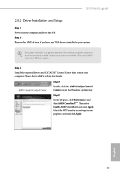
... Performance and then AMD CrossFireXTM. Select the GPU number according to uninstall any VGA drivers installed in the Windows® system tray. Step 3 Install the required drivers and CATALYST Control Center then restart your computer and boot into OS. Then select Enable AMD CrossFireX and click Apply. X570 Steel Legend 2.8.2 Driver Installation and Setup Step 1 Power on your computer. The Catalyst Uninstaller is an optional download. Please check AMD's website for...
... Performance and then AMD CrossFireXTM. Select the GPU number according to uninstall any VGA drivers installed in the Windows® system tray. Step 3 Install the required drivers and CATALYST Control Center then restart your computer and boot into OS. Then select Enable AMD CrossFireX and click Apply. X570 Steel Legend 2.8.2 Driver Installation and Setup Step 1 Power on your computer. The Catalyst Uninstaller is an optional download. Please check AMD's website for...
User Manual
Page 54
... Main Menu does not appear automatically, locate and double click on the support CD driver page. Chapter 3 Software and Utilities Operation 3.1 Installing Drivers The Support CD that comes with the motherboard contains necessary drivers and useful utilities that the motherboard supports. Utilities Menu The Utilities Menu shows the application software that enhance the motherboard's features. Drivers Menu The drivers compatible to your system will be auto-detected and listed on the file "ASRSETUP.EXE" in your CD-ROM drive. Please click Install...
... Main Menu does not appear automatically, locate and double click on the support CD driver page. Chapter 3 Software and Utilities Operation 3.1 Installing Drivers The Support CD that comes with the motherboard contains necessary drivers and useful utilities that the motherboard supports. Utilities Menu The Utilities Menu shows the application software that enhance the motherboard's features. Drivers Menu The drivers compatible to your system will be auto-detected and listed on the file "ASRSETUP.EXE" in your CD-ROM drive. Please click Install...

User Manual
Page 70
... support memory and Infinity 64 English CPU Frequency and Voltage Change If this item is depending on the CPU's capability. Disable to reduce electromagnetic interference for reference purpose only, and they may not exactly match what you can set based on user selection. 4.3 OC Tweaker Screen In the OC Tweaker screen, you see on your screen. CPU Configuration Spread Spectrum Enable Spread Spectrum to achieve higher clock speeds...
... support memory and Infinity 64 English CPU Frequency and Voltage Change If this item is depending on the CPU's capability. Disable to reduce electromagnetic interference for reference purpose only, and they may not exactly match what you can set based on user selection. 4.3 OC Tweaker Screen In the OC Tweaker screen, you see on your screen. CPU Configuration Spread Spectrum Enable Spread Spectrum to achieve higher clock speeds...
RAID Installation Guide
Page 8
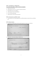
...STEP 4: Windows installation A. Please install the DVD-ROM. D. During Windows installation process, when Disk selection page show up, please click . Go to enter UEFI setup utility. B. Click to find the driver inside your USB flash disk. Insert the Support CD into one of the USB port. Plug a USB drive into the DVD-ROM drive. During system boot, press or key to Tools Easy RAID Installer F. Please download the "SATA Floppy Imaged driver" from ASRock's website A. Follow instructions to finish the configuration. STEP 3.1: Copy RAID driver to a USB flash drive You...
...STEP 4: Windows installation A. Please install the DVD-ROM. D. During Windows installation process, when Disk selection page show up, please click . Go to enter UEFI setup utility. B. Click to find the driver inside your USB flash disk. Insert the Support CD into one of the USB port. Plug a USB drive into the DVD-ROM drive. During system boot, press or key to Tools Easy RAID Installer F. Please download the "SATA Floppy Imaged driver" from ASRock's website A. Follow instructions to finish the configuration. STEP 3.1: Copy RAID driver to a USB flash drive You...
RAID Installation Guide
Page 15
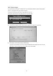
... your USB flash drive. Then restart the system. B. Click to open the F11 boot menu again. If the system restarts at this point, then please open the boot menu that is shown in this system is the first. A. Three drivers must be loaded. While this picture. STEP 3: Windows installation Insert the USB drive with Windows 10 installation files. Using SATA/NVMe RAID driver package (version 9.2.0.127) from . It should list the USB drive as a UEFI device.
... your USB flash drive. Then restart the system. B. Click to open the F11 boot menu again. If the system restarts at this point, then please open the boot menu that is shown in this system is the first. A. Three drivers must be loaded. While this picture. STEP 3: Windows installation Insert the USB drive with Windows 10 installation files. Using SATA/NVMe RAID driver package (version 9.2.0.127) from . It should list the USB drive as a UEFI device.


