

User Manual
Page 6
... 1 1.1 Package Contents 1 1.2 Specifications 2 1.3 Motherboard Layout 8 1.4 I/O Panel 10 Chapter 2 Installation 14 2.1 Removing the Water-cooling Module 15 2.4 Installing Memory Modules (DIMM) 28 2.5 Installing the Motherboard 31 2.6 Expansion Slots (PCI Express Slots) 32 2.7 Connecting Graphics Card to DisplayPort Input 34 2.8 Onboard Headers and Connectors 36 2.9 Smart Switches 42 2.10 Dr. Debug 44 2.11 SLITM and Quad SLITM Operation Guide 50 2.11.1 Installing Two SLITM-Ready Graphics Cards 50 2.11.2 Driver Installation and Setup 52 2.12 CrossFireXTM , 3-Way...
... 1 1.1 Package Contents 1 1.2 Specifications 2 1.3 Motherboard Layout 8 1.4 I/O Panel 10 Chapter 2 Installation 14 2.1 Removing the Water-cooling Module 15 2.4 Installing Memory Modules (DIMM) 28 2.5 Installing the Motherboard 31 2.6 Expansion Slots (PCI Express Slots) 32 2.7 Connecting Graphics Card to DisplayPort Input 34 2.8 Onboard Headers and Connectors 36 2.9 Smart Switches 42 2.10 Dr. Debug 44 2.11 SLITM and Quad SLITM Operation Guide 50 2.11.1 Installing Two SLITM-Ready Graphics Cards 50 2.11.2 Driver Installation and Setup 52 2.12 CrossFireXTM , 3-Way...

User Manual
Page 7
...(NGFF) Module Installation Guide (M2_2) 60 Chapter 3 Software and Utilities Operation 63 3.1 Installing Drivers 63 3.2 A-Tuning 64 3.2.1 Installing A-Tuning 64 3.2.2 Using A-Tuning 64 3.3 ASRock Live Update & APP Shop 67 3.3.1 UI Overview 67 3.3.2 Apps 68 3.3.3 BIOS & Drivers 71 3.3.4 Setting 72 3.4 ASRock Polychrome SYNC 73 Chapter 4 UEFI SETUP UTILITY 76 4.1 Introduction 76 4.1.1 UEFI Menu Bar 76 4.1.2 Navigation Keys 77 4.2 Main Screen 78 4.3 OC Tweaker Screen 79 4.4 Advanced Screen 83 4.4.1 CPU Configuration 84 4.4.2 Onboard Devices Configuration 85...
...(NGFF) Module Installation Guide (M2_2) 60 Chapter 3 Software and Utilities Operation 63 3.1 Installing Drivers 63 3.2 A-Tuning 64 3.2.1 Installing A-Tuning 64 3.2.2 Using A-Tuning 64 3.3 ASRock Live Update & APP Shop 67 3.3.1 UI Overview 67 3.3.2 Apps 68 3.3.3 BIOS & Drivers 71 3.3.4 Setting 72 3.4 ASRock Polychrome SYNC 73 Chapter 4 UEFI SETUP UTILITY 76 4.1 Introduction 76 4.1.1 UEFI Menu Bar 76 4.1.2 Navigation Keys 77 4.2 Main Screen 78 4.3 OC Tweaker Screen 79 4.4 Advanced Screen 83 4.4.1 CPU Configuration 84 4.4.2 Onboard Devices Configuration 85...
User Manual
Page 9
... latest VGA cards and CPU support list on ASRock's website without notice. If you require technical support related to change without further notice. Chapter 4 contains the configuration guide of the motherboard and step-by-step installation guides. ASRock website http://www.asrock.com. 1.1 Package Contents • ASRock X570 AQUA Motherboard (EATX Form Factor) • ASRock X570 AQUA Quick Installation Guide • ASRock X570 AQUA Support CD • 4 x Serial ATA (SATA) Data Cables (Optional) • 1 x ASRock SLI_HB_Bridge_2S Card (Optional) • 1 x ASRock WiFi 2.4/5 GHz...
... latest VGA cards and CPU support list on ASRock's website without notice. If you require technical support related to change without further notice. Chapter 4 contains the configuration guide of the motherboard and step-by-step installation guides. ASRock website http://www.asrock.com. 1.1 Package Contents • ASRock X570 AQUA Motherboard (EATX Form Factor) • ASRock X570 AQUA Quick Installation Guide • ASRock X570 AQUA Support CD • 4 x Serial ATA (SATA) Data Cables (Optional) • 1 x ASRock SLI_HB_Bridge_2S Card (Optional) • 1 x ASRock WiFi 2.4/5 GHz...

User Manual
Page 11
... Audio) with HDMI 2.0 Ports (Compliant HDMI monitor is only supported with Ryzen Series CPUs (Matisse and Pinnacle Ridge). • 1 x Vertical M.2 Socket (Key E) with the bundled WiFi802.11ax module (on the CPU installed. * Supports NVMe SSD as boot disks • 3 x PCI Express 2.0 x1 Slots • Supports AMD Quad CrossFireXTM, 3-Way CrossFireXTM and CrossFireXTM • Supports NVIDIA® Quad SLITM and SLITM** • Supports NVIDIA® NVLinkTM with dual NVIDIA® GeForce® RTX series graphics cards...
... Audio) with HDMI 2.0 Ports (Compliant HDMI monitor is only supported with Ryzen Series CPUs (Matisse and Pinnacle Ridge). • 1 x Vertical M.2 Socket (Key E) with the bundled WiFi802.11ax module (on the CPU installed. * Supports NVMe SSD as boot disks • 3 x PCI Express 2.0 x1 Slots • Supports AMD Quad CrossFireXTM, 3-Way CrossFireXTM and CrossFireXTM • Supports NVIDIA® Quad SLITM and SLITM** • Supports NVIDIA® NVLinkTM with dual NVIDIA® GeForce® RTX series graphics cards...
User Manual
Page 13
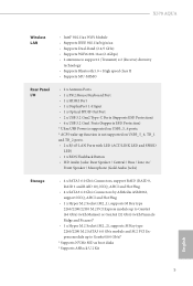
... ports. * ACPI wake-up function is not supported on USB3_5_6, TB_1 and TB_2 ports. • 2 x RJ-45 LAN Ports with LED (ACT/LINK LED and SPEED LED) • 1 x BIOS Flashback Button • HD Audio Jacks: Rear Speaker / Central / Bass / Line in / Front Speaker / Microphone (Gold Audio Jacks) Storage • 4 x SATA3 6.0 Gb/s Connectors, support RAID (RAID 0, RAID 1 and RAID 10), NCQ, AHCI and Hot Plug • 4 x SATA3 6.0 Gb/s Connectors by ASMedia ASM1061, support NCQ, AHCI and Hot Plug • 1 x Hyper M.2 Socket (M2_1), supports M Key type...
... ports. * ACPI wake-up function is not supported on USB3_5_6, TB_1 and TB_2 ports. • 2 x RJ-45 LAN Ports with LED (ACT/LINK LED and SPEED LED) • 1 x BIOS Flashback Button • HD Audio Jacks: Rear Speaker / Central / Bass / Line in / Front Speaker / Microphone (Gold Audio Jacks) Storage • 4 x SATA3 6.0 Gb/s Connectors, support RAID (RAID 0, RAID 1 and RAID 10), NCQ, AHCI and Hot Plug • 4 x SATA3 6.0 Gb/s Connectors by ASMedia ASM1061, support NCQ, AHCI and Hot Plug • 1 x Hyper M.2 Socket (M2_1), supports M Key type...

User Manual
Page 14
...8226; 1 x CPU Fan Connector (4-pin) * The CPU Fan Connector supports the CPU fan of maximum 1A (12W) fan power. • 1 x CPU/Water Pump Fan Connector (4-pin) (Smart Fan Speed Control) * The CPU/Water Pump Fan supports the water cooler fan of maximum 2A (24W) fan power. • 3 x Chassis/Water Pump Fan Connectors (4-pin) (Smart Fan Speed Control) * The Chassis/Water Pump Fan supports the water cooler fan of maximum 2A (24W) fan power. * CPU_FAN2/WP, CHA_FAN1/WP, CHA_FAN2/WP and CHA_FAN3/WP can auto detect if 3-pin or 4-pin fan is compatible with LED • 1 x Clear CMOS Button English...
...8226; 1 x CPU Fan Connector (4-pin) * The CPU Fan Connector supports the CPU fan of maximum 1A (12W) fan power. • 1 x CPU/Water Pump Fan Connector (4-pin) (Smart Fan Speed Control) * The CPU/Water Pump Fan supports the water cooler fan of maximum 2A (24W) fan power. • 3 x Chassis/Water Pump Fan Connectors (4-pin) (Smart Fan Speed Control) * The Chassis/Water Pump Fan supports the water cooler fan of maximum 2A (24W) fan power. * CPU_FAN2/WP, CHA_FAN1/WP, CHA_FAN2/WP and CHA_FAN3/WP can auto detect if 3-pin or 4-pin fan is compatible with LED • 1 x Clear CMOS Button English...
User Manual
Page 15
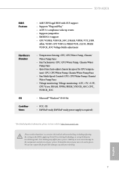
... setting in the BIOS, applying Untied Overclocking Technology, or using third-party overclocking tools. X570 AQUA BIOS Feature Hardware Monitor OS Certifications • AMI UEFI Legal BIOS with GUI support • Supports "Plug and Play" • ACPI 5.1 compliance wake up events • Supports jumperfree • SMBIOS 2.3 support • CPU VCORE, VDDCR_SOC, DRAM, VPPM, VTT_DDR offset, VDDP, CPU VDD1.8, PREM VDD_CLDO, PREM VDDCR_SOC Voltage Multi-adjustment • Temperature Sensing: CPU, CPU/Water Pump, Chassis/ Water Pump Fans • Fan Tachometer: CPU, CPU...
... setting in the BIOS, applying Untied Overclocking Technology, or using third-party overclocking tools. X570 AQUA BIOS Feature Hardware Monitor OS Certifications • AMI UEFI Legal BIOS with GUI support • Supports "Plug and Play" • ACPI 5.1 compliance wake up events • Supports jumperfree • SMBIOS 2.3 support • CPU VCORE, VDDCR_SOC, DRAM, VPPM, VTT_DDR offset, VDDP, CPU VDD1.8, PREM VDD_CLDO, PREM VDDCR_SOC Voltage Multi-adjustment • Temperature Sensing: CPU, CPU/Water Pump, Chassis/ Water Pump Fans • Fan Tachometer: CPU, CPU...

User Manual
Page 17
...-pin DDR4 DIMM Slots (DDR4_A2, DDR4_B2) 8 AMD FAN LED Header (AMD_FAN_LED1) 9 ATX Power Connector (ATXPWR1) 10 USB 3.2 Gen1 Header (USB3_7_8) 11 Chassis / Waterpump Fan Connector (CHA_FAN1/WP) 12 Front Panel Type C USB 3.2 Gen2 Header (F_USB31_TC_1) 13 SATA3 Connectors (SATA3_1_2) 14 SATA3 Connectors (SATA3_3_4) 15 SATA3 Connectors (SATA3_A1_A2) 16 SATA3 Connectors (SATA3_A3_A4) 17 System Panel Header (PANEL1) 18 Clear CMOS Button (CLRCBTN1) 19 Power Button (PWRBTN1) 20 Reset Button (RSTBTN1) 21 Power LED and Speaker Header (SPK_PLED1) 22 Chassis/Water Pump Fan Connector (CHA_FAN2/WP) 23 USB...
...-pin DDR4 DIMM Slots (DDR4_A2, DDR4_B2) 8 AMD FAN LED Header (AMD_FAN_LED1) 9 ATX Power Connector (ATXPWR1) 10 USB 3.2 Gen1 Header (USB3_7_8) 11 Chassis / Waterpump Fan Connector (CHA_FAN1/WP) 12 Front Panel Type C USB 3.2 Gen2 Header (F_USB31_TC_1) 13 SATA3 Connectors (SATA3_1_2) 14 SATA3 Connectors (SATA3_3_4) 15 SATA3 Connectors (SATA3_A1_A2) 16 SATA3 Connectors (SATA3_A3_A4) 17 System Panel Header (PANEL1) 18 Clear CMOS Button (CLRCBTN1) 19 Power Button (PWRBTN1) 20 Reset Button (RSTBTN1) 21 Power LED and Speaker Header (SPK_PLED1) 22 Chassis/Water Pump Fan Connector (CHA_FAN2/WP) 23 USB...

User Manual
Page 40
... the power supply is switched off or the power cord is used for PCI Express x8 lane width graphics cards. PCIE2 (PCIe 2.0 x1 slot) is used for PCI Express x4 lane width graphics cards. 2.6 Expansion Slots (PCI Express Slots) There are 6 PCI Express slots on the motherboard. PCIE4 (PCIe 4.0 x16 slot) is used for PCI Express x1 lane width cards. Before installing an expansion card, please make necessary hardware settings for PCI Express x1 lane width cards. PCIE5 (PCIe 2.0 x1 slot) is unplugged. PCIE3 (PCIe 2.0 x1 slot) is used for the card...
... the power supply is switched off or the power cord is used for PCI Express x8 lane width graphics cards. PCIE2 (PCIe 2.0 x1 slot) is used for PCI Express x4 lane width graphics cards. 2.6 Expansion Slots (PCI Express Slots) There are 6 PCI Express slots on the motherboard. PCIE4 (PCIe 4.0 x16 slot) is used for PCI Express x1 lane width cards. Before installing an expansion card, please make necessary hardware settings for PCI Express x1 lane width cards. PCIE5 (PCIe 2.0 x1 slot) is unplugged. PCIE3 (PCIe 2.0 x1 slot) is used for the card...

User Manual
Page 48
... use a 4-pin ATX power supply, please plug it along Pin 1 and Pin 5. *Warning: Please make sure that comes with a regular RGB LED stripe. The cable connection allows users to connect RGB LED extension cable that the power cable connected is compatible with AMD heatsink. ATX 12V Power Connector (8-pin ATX12V1) (see p.8, No. 1) 8 5 4 1 ATX 12V Power Connector (4-pin ATX12V2) (see p.8, No. 2) AMD FAN LED Header (4-pin AMD_FAN_ LED1) (see p.8, No. 8) 1 12V G R B This motherboard provides an 8-pin ATX 12V power connector. English 40 Do not plug the PCIe power cable to this connector...
... use a 4-pin ATX power supply, please plug it along Pin 1 and Pin 5. *Warning: Please make sure that comes with a regular RGB LED stripe. The cable connection allows users to connect RGB LED extension cable that the power cable connected is compatible with AMD heatsink. ATX 12V Power Connector (8-pin ATX12V1) (see p.8, No. 1) 8 5 4 1 ATX 12V Power Connector (4-pin ATX12V2) (see p.8, No. 2) AMD FAN LED Header (4-pin AMD_FAN_ LED1) (see p.8, No. 8) 1 12V G R B This motherboard provides an 8-pin ATX 12V power connector. English 40 Do not plug the PCIe power cable to this connector...

User Manual
Page 49
... allows users to choose from various LED lighting effects. otherwise, the cable may be damaged. *Please refer to page 74 for further instructions on this header. This connector is used to connect a graphics card or a DisplayPort compatible device. otherwise, the cable may be damaged. *Please refer to page 73 for further instructions on this header. Caution: Never install the Addressable LED cable in the wrong orientation; English 41 X570 AQUA RGB LED Header (4-pin...
... allows users to choose from various LED lighting effects. otherwise, the cable may be damaged. *Please refer to page 74 for further instructions on this header. This connector is used to connect a graphics card or a DisplayPort compatible device. otherwise, the cable may be damaged. *Please refer to page 73 for further instructions on this header. Caution: Never install the Addressable LED cable in the wrong orientation; English 41 X570 AQUA RGB LED Header (4-pin...

User Manual
Page 50
.... 20) Reset Reset Button allows users to quickly reset the system. English 42 2.9 Smart Switches The motherboard has four smart switches: Power Button, Reset Button, Clear CMOS Button and BIOS Flashback Button, allowing users to quickly turn on /off your computer and unplug the power supply. Reset Button (RSTBTN) (see p.8, No. 19) Power Power Button allows users to quickly clear the CMOS values. This function is workable only when you power off the system, reset the system, clear the CMOS values or flash the BIOS. Clear CMOS Button (CLRCBTN1) (see...
.... 20) Reset Reset Button allows users to quickly reset the system. English 42 2.9 Smart Switches The motherboard has four smart switches: Power Button, Reset Button, Clear CMOS Button and BIOS Flashback Button, allowing users to quickly turn on /off your computer and unplug the power supply. Reset Button (RSTBTN) (see p.8, No. 19) Power Power Button allows users to quickly clear the CMOS values. This function is workable only when you power off the system, reset the system, clear the CMOS values or flash the BIOS. Clear CMOS Button (CLRCBTN1) (see...

User Manual
Page 51
... LED starts to the root directory of your USB drive to the USB BIOS Flashback port. 7. Extract BIOS file from ASRock's website : http://www.asrock.com. 2. Then turn on the system. 6. Download the latest BIOS file from the zip file. 4. Plug the 24 pin power connector to power on the power supply's AC switch. *There is not operating properly. Copy the BIOS file to flash the BIOS. X570 AQUA BIOS Flashback Button (BIOS_FB1) (see p.10, No. 19) BIOS Flashback Button allows users to your USB flash drive. To use...
... LED starts to the root directory of your USB drive to the USB BIOS Flashback port. 7. Extract BIOS file from ASRock's website : http://www.asrock.com. 2. Then turn on the system. 6. Download the latest BIOS file from the zip file. 4. Plug the 24 pin power connector to power on the power supply's AC switch. *There is not operating properly. Copy the BIOS file to flash the BIOS. X570 AQUA BIOS Flashback Button (BIOS_FB1) (see p.10, No. 19) BIOS Flashback Button allows users to your USB flash drive. To use...

User Manual
Page 58
... SLITM Operation Guide This motherboard supports NVIDIA® SLITM and Quad SLITM (Scalable Link Interface) technology that your power supply unit (PSU) can provide at least the minimum power your graphics card driver supports NVIDIA® SLITM technology. You should only use a NVIDIA® certified PSU. Download the drivers from the NVIDIA® website: www.nvidia.com 3. It is recommended to two identical PCI Express x16 graphics cards. Make...
... SLITM Operation Guide This motherboard supports NVIDIA® SLITM and Quad SLITM (Scalable Link Interface) technology that your power supply unit (PSU) can provide at least the minimum power your graphics card driver supports NVIDIA® SLITM technology. You should only use a NVIDIA® certified PSU. Download the drivers from the NVIDIA® website: www.nvidia.com 3. It is recommended to two identical PCI Express x16 graphics cards. Make...

User Manual
Page 61
... use identical CrossFireXTM-ready graphics cards that the cards are AMD certified. 2. Make sure that your system requires. Different CrossFireXTM cards may require different methods to three identical PCI Express x16 graphics cards. 1. Download the drivers from the AMD's website: www.amd.com 3. X570 AQUA 2.12 CrossFireXTM , 3-Way CrossFireXTM and Quad CrossFireXTM Operation Guide This motherboard supports CrossFireXTM, 3-way CrossFireXTM and Quad CrossFireXTM that allows you to install up to enable...
... use identical CrossFireXTM-ready graphics cards that the cards are AMD certified. 2. Make sure that your system requires. Different CrossFireXTM cards may require different methods to three identical PCI Express x16 graphics cards. 1. Download the drivers from the AMD's website: www.amd.com 3. X570 AQUA 2.12 CrossFireXTM , 3-Way CrossFireXTM and Quad CrossFireXTM Operation Guide This motherboard supports CrossFireXTM, 3-way CrossFireXTM and Quad CrossFireXTM that allows you to install up to enable...
User Manual
Page 64
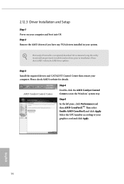
... AMD's website for AMD driver updates. Select the GPU number according to installation. 2.12.3 Driver Installation and Setup Step 1 Power on your computer. AMD Catalyst Control Center Step 4 Double-click the AMD Catalyst Control Center icon in your graphics card and click Apply. Step 3 Install the required drivers and CATALYST Control Center then restart your computer and boot into OS. English 56 The Catalyst Uninstaller is an optional download. Then select Enable AMD...
... AMD's website for AMD driver updates. Select the GPU number according to installation. 2.12.3 Driver Installation and Setup Step 1 Power on your computer. AMD Catalyst Control Center Step 4 Double-click the AMD Catalyst Control Center icon in your graphics card and click Apply. Step 3 Install the required drivers and CATALYST Control Center then restart your computer and boot into OS. English 56 The Catalyst Uninstaller is an optional download. Then select Enable AMD...
User Manual
Page 71
Drivers Menu The drivers compatible to install those required drivers. Click on a specific item then follow the order from top to bottom to your system will be auto-detected and listed on the file "ASRSETUP.EXE" in your CD-ROM drive. If the Main Menu does not appear automatically, locate and double click on the support CD driver page. Utilities Menu The Utilities Menu shows the application software that enhance the motherboard's features. The...
Drivers Menu The drivers compatible to install those required drivers. Click on a specific item then follow the order from top to bottom to your system will be auto-detected and listed on the file "ASRSETUP.EXE" in your CD-ROM drive. If the Main Menu does not appear automatically, locate and double click on the support CD driver page. Utilities Menu The Utilities Menu shows the application software that enhance the motherboard's features. The...

User Manual
Page 88
... after selecting [Auto]. CLDO VDDG Voltage VDDG represents voltage for DDR4 modules. DRAM Timing Configuration Load XMP Setting Load XMP settings to support memory and Infinity Fabric overclocking. GFX Clock Frequency (Only for processor with integrated graphics. VDD_SOC also determines the GPU voltage on processors with integrated graphics) This item allows you alter the GFX Clock Frequency settings, make sure to force this voltage. To re-enable SMT, a power cycle is selected, the motherboard will detect...
... after selecting [Auto]. CLDO VDDG Voltage VDDG represents voltage for DDR4 modules. DRAM Timing Configuration Load XMP Setting Load XMP settings to support memory and Infinity Fabric overclocking. GFX Clock Frequency (Only for processor with integrated graphics. VDD_SOC also determines the GPU voltage on processors with integrated graphics) This item allows you alter the GFX Clock Frequency settings, make sure to force this voltage. To re-enable SMT, a power cycle is selected, the motherboard will detect...

User Manual
Page 92
... disabled. SMT Mode This item can utilize the additional hardware capabilities provided by AMD-V. 4.4.1 CPU Configuration PSS Support Use this to enable or disable NX mode. SVM Mode When this to disable symmetric multithreading. Warning: S3 is not supported on systems where SMT is needed after selecting [Auto]. The default value is set to [Enabled], a VMM (Virtual Machine Architecture)can be used to enable or disable AMD CPU fTPM. 84 English AMD fTPM Switch Use this is [Enabled...
... disabled. SMT Mode This item can utilize the additional hardware capabilities provided by AMD-V. 4.4.1 CPU Configuration PSS Support Use this to enable or disable NX mode. SVM Mode When this to disable symmetric multithreading. Warning: S3 is not supported on systems where SMT is needed after selecting [Auto]. The default value is set to [Enabled], a VMM (Virtual Machine Architecture)can be used to enable or disable AMD CPU fTPM. 84 English AMD fTPM Switch Use this is [Enabled...

User Manual
Page 106
... support legacy option ROM only. Please do not disable unless you 've enabled Full Screen Logo. Select Do not launch to not execute both legacy and UEFI option ROM. 98 English AddOn ROM Display Enable AddOn ROM Display to be decoded in Above 4G Address Space (only if the system supports 64 bit PCI decoding). Above 4G Decoding Enable or disable 64bit capable Devices to see the AddOn ROM messages or configure the AddOn ROM...
... support legacy option ROM only. Please do not disable unless you 've enabled Full Screen Logo. Select Do not launch to not execute both legacy and UEFI option ROM. 98 English AddOn ROM Display Enable AddOn ROM Display to be decoded in Above 4G Address Space (only if the system supports 64 bit PCI decoding). Above 4G Decoding Enable or disable 64bit capable Devices to see the AddOn ROM messages or configure the AddOn ROM...


