
RAID Installation Guide
Page 2
... provide any HDDs of the same model and capacity when creating a RAID set the option to RAID mode by following the detailed instruction of the "User Manual" in our support CD, then you can improve the access performance, it will direct all applications to configure RAID functions by using the onboard FastBuild BIOS utility under BIOS environment. Although RAID 0 function can start to use the onboard RAID Option ROM Utility to configure RAID. 1.1 Introduction to RAID The term "RAID" stands for...
... provide any HDDs of the same model and capacity when creating a RAID set the option to RAID mode by following the detailed instruction of the "User Manual" in our support CD, then you can improve the access performance, it will direct all applications to configure RAID functions by using the onboard FastBuild BIOS utility under BIOS environment. Although RAID 0 function can start to use the onboard RAID Option ROM Utility to configure RAID. 1.1 Introduction to RAID The term "RAID" stands for...

RAID Installation Guide
Page 8
... . Click to finish the configuration. STEP 3.1: Copy RAID driver to a USB flash drive You can choose either STEP 3.1 or STEP 3.2 to find the driver inside your USB flash disk. Please install the DVD-ROM. STEP 3.2: Download driver from ASRock's website and unzip the file into the DVD-ROM drive. C. Plug a USB drive into one of the USB port. Go to finish the driver copy process. Follow instructions to Tools Easy RAID Installer F. During system boot, press or key to enter UEFI setup utility. B. B. A. D. STEP 4: Windows installation A.
... . Click to finish the configuration. STEP 3.1: Copy RAID driver to a USB flash drive You can choose either STEP 3.1 or STEP 3.2 to find the driver inside your USB flash disk. Please install the DVD-ROM. STEP 3.2: Download driver from ASRock's website and unzip the file into the DVD-ROM drive. C. Plug a USB drive into one of the USB port. Go to finish the driver copy process. Follow instructions to Tools Easy RAID Installer F. During system boot, press or key to enter UEFI setup utility. B. B. A. D. STEP 4: Windows installation A.

RAID Installation Guide
Page 12
... A. Plug a USB drive into the DVD-ROM drive. Insert the Support CD into one of the USB port. STEP 2.2: Download driver from ASRock's website and unzip the file into your USB flash disk. 12 Click to save to delete the existing disk arrays before creating a new array. STEP 2.1: Copy RAID driver to a USB flash drive You can choose either STEP2.1 or STEP2.2 to enter UEFI setup utility. Please install the DVD-ROM. During system boot, press or key to finish the configuration...
... A. Plug a USB drive into the DVD-ROM drive. Insert the Support CD into one of the USB port. STEP 2.2: Download driver from ASRock's website and unzip the file into your USB flash disk. 12 Click to save to delete the existing disk arrays before creating a new array. STEP 2.1: Copy RAID driver to a USB flash drive You can choose either STEP2.1 or STEP2.2 to enter UEFI setup utility. Please install the DVD-ROM. During system boot, press or key to finish the configuration...

Quick Installation Guide
Page 5
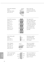
... 288-pin DDR4 DIMM Slots (DDR4_A2, DDR4_B2) 8 ATX Power Connector (ATXPWR1) 9 USB 3.1 Gen1 Header (USB3_7_8) 10 CPU / Waterpump Fan Connector (CHA_FAN1/WP) 11 AMD LED Fan USB Header (USB_5) 12 Front Panel Type C USB 3.1 Gen2 Header (F_USB31_TC_1) 13 AMD FAN LED Header (AMD_FAN_LED1) 14 USB 3.1 Gen1 Header (USB3_9_10) 15 SATA3 Connectors (SATA3_1_2) 16 SATA3 Connectors (SATA3_3_4) 17 SATA3 Connectors (SATA3_5_6) 18 SATA3 Connectors (SATA3_A1_A2) 19 Clear CMOS Jumper (CLRCMOS1) 20 System Panel Header (PANEL1) 21 USB 2.0 Header (USB_1_2) 22 USB 2.0 Header (USB_3_4) 23 Power LED and Speaker Header...
... 288-pin DDR4 DIMM Slots (DDR4_A2, DDR4_B2) 8 ATX Power Connector (ATXPWR1) 9 USB 3.1 Gen1 Header (USB3_7_8) 10 CPU / Waterpump Fan Connector (CHA_FAN1/WP) 11 AMD LED Fan USB Header (USB_5) 12 Front Panel Type C USB 3.1 Gen2 Header (F_USB31_TC_1) 13 AMD FAN LED Header (AMD_FAN_LED1) 14 USB 3.1 Gen1 Header (USB3_9_10) 15 SATA3 Connectors (SATA3_1_2) 16 SATA3 Connectors (SATA3_3_4) 17 SATA3 Connectors (SATA3_5_6) 18 SATA3 Connectors (SATA3_A1_A2) 19 Clear CMOS Jumper (CLRCMOS1) 20 System Panel Header (PANEL1) 21 USB 2.0 Header (USB_1_2) 22 USB 2.0 Header (USB_3_4) 23 Power LED and Speaker Header...
Quick Installation Guide
Page 8
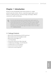
...; ASRock X470 Taichi Motherboard (ATX Form Factor) • ASRock X470 Taichi Quick Installation Guide • ASRock X470 Taichi Support CD • 1 x I/O Panel Shield • 4 x Serial ATA (SATA) Data Cables (Optional) • 1 x ASRock SLI_HB_Bridge_2S Card (Optional) • 2 x ASRock WiFi 2.4/5 GHz Antennas • 2 x Screws for M.2 Socket (Optional) • 1 x Nut for purchasing ASRock X470 Taichi motherboard, a reliable motherboard produced under ASRock's consistently stringent quality control. Because the motherboard specifications and the BIOS software might be updated, the...
...; ASRock X470 Taichi Motherboard (ATX Form Factor) • ASRock X470 Taichi Quick Installation Guide • ASRock X470 Taichi Support CD • 1 x I/O Panel Shield • 4 x Serial ATA (SATA) Data Cables (Optional) • 1 x ASRock SLI_HB_Bridge_2S Card (Optional) • 2 x ASRock WiFi 2.4/5 GHz Antennas • 2 x Screws for M.2 Socket (Optional) • 1 x Nut for purchasing ASRock X470 Taichi motherboard, a reliable motherboard produced under ASRock's consistently stringent quality control. Because the motherboard specifications and the BIOS software might be updated, the...

Quick Installation Guide
Page 12
..., AHCI and Hot Plug • 1 x Ultra M.2 Socket (M2_1), supports M Key type 2260/2280/22110 M.2 SATA3 6.0 Gb/s module and M.2 PCI Express module up to Gen3 x4 (32 Gb/s)* • 1 x M.2 Socket (M2_2), supports M Key type 2230/2242/2260/2280 M.2 PCI Express module up to Gen2 x4 (20 Gb/s)* * If M2_2 is occupied, PCIE5 slot will be disabled * Supports NVMe SSD as boot disks * Supports ASRock U.2 Kit Connector • 1 x Power LED and Speaker Header • 1 x AMD Fan LED Header * The AMD Fan LED Header supports LED strips of maximum load...
..., AHCI and Hot Plug • 1 x Ultra M.2 Socket (M2_1), supports M Key type 2260/2280/22110 M.2 SATA3 6.0 Gb/s module and M.2 PCI Express module up to Gen3 x4 (32 Gb/s)* • 1 x M.2 Socket (M2_2), supports M Key type 2230/2242/2260/2280 M.2 PCI Express module up to Gen2 x4 (20 Gb/s)* * If M2_2 is occupied, PCIE5 slot will be disabled * Supports NVMe SSD as boot disks * Supports ASRock U.2 Kit Connector • 1 x Power LED and Speaker Header • 1 x AMD Fan LED Header * The AMD Fan LED Header supports LED strips of maximum load...

Quick Installation Guide
Page 13
...Connector (15μ Gold Audio Connector) • 1 x AMD LED Fan USB Header • 2 x USB 2.0 Headers (Support 4 USB 2.0 ports) (Supports ESD Protection) • 2 x USB 3.1 Gen1 Headers (Support 4 USB 3.1 Gen1 ports) (Supports ESD Protection) • 1 x Front Panel Type C USB 3.1 Gen2 Header (ASMedia ASM3142) • 1 x Dr. Debug with LED • AMI UEFI Legal BIOS with GUI support • Supports "Plug and Play" • ACPI 5.1 compliance wake up events • Supports jumperfree • SMBIOS 2.3 support • CPU, VCORE_NB, DRAM, VPPM, PCH 1.05V, +1.8V, VDDP, PROM 2.5V, Voltage...
...Connector (15μ Gold Audio Connector) • 1 x AMD LED Fan USB Header • 2 x USB 2.0 Headers (Support 4 USB 2.0 ports) (Supports ESD Protection) • 2 x USB 3.1 Gen1 Headers (Support 4 USB 3.1 Gen1 ports) (Supports ESD Protection) • 1 x Front Panel Type C USB 3.1 Gen2 Header (ASMedia ASM3142) • 1 x Dr. Debug with LED • AMI UEFI Legal BIOS with GUI support • Supports "Plug and Play" • ACPI 5.1 compliance wake up events • Supports jumperfree • SMBIOS 2.3 support • CPU, VCORE_NB, DRAM, VPPM, PCH 1.05V, +1.8V, VDDP, PROM 2.5V, Voltage...
Quick Installation Guide
Page 35
... ports. USB 3.1 Gen1 Headers (19-pin USB3_7_8) (see p.1, No. 18) SPEAKER DUMMY DUMMY +5V 1 PLED+ PLED+ PLED- These eight SATA3 connectors support SATA data cables for internal storage devices with up to this motherboard. Each USB 2.0 header can support two ports. 32 English Please connect the chassis power LED and the chassis speaker to 6.0 Gb/s data transfer rate. * To minimize the boot time, use AMD SATA ports (SATA3_1~6) for connecting the USB connector on this header. There are two headers on the AMD SR3 Heatsink...
... ports. USB 3.1 Gen1 Headers (19-pin USB3_7_8) (see p.1, No. 18) SPEAKER DUMMY DUMMY +5V 1 PLED+ PLED+ PLED- These eight SATA3 connectors support SATA data cables for internal storage devices with up to this motherboard. Each USB 2.0 header can support two ports. 32 English Please connect the chassis power LED and the chassis speaker to 6.0 Gb/s data transfer rate. * To minimize the boot time, use AMD SATA ports (SATA3_1~6) for connecting the USB connector on this header. There are two headers on the AMD SR3 Heatsink...
Quick Installation Guide
Page 41
Please press reset or clear CMOS. 92 - 99 Problem related to IDE or SATA devices. Please re-install PCI-E devices or try using other USB, PCI devices. 01 - 54 (except 0d), 5A- 60 Problem related to memory. If the problem still exists, please remove all SATA devices. Please re-install IDE and SATA devices. Code Description 00 Please check if the CPU is used to provide code information, which makes troubleshooting even easier. Please re-install the memory and CPU. If the problem still...
Please press reset or clear CMOS. 92 - 99 Problem related to IDE or SATA devices. Please re-install PCI-E devices or try using other USB, PCI devices. 01 - 54 (except 0d), 5A- 60 Problem related to memory. If the problem still exists, please remove all SATA devices. Please re-install IDE and SATA devices. Code Description 00 Please check if the CPU is used to provide code information, which makes troubleshooting even easier. Please re-install the memory and CPU. If the problem still...
User Manual
Page 9
...Quick Installation Guide • ASRock X470 Taichi Support CD • 1 x I/O Panel Shield • 4 x Serial ATA (SATA) Data Cables (Optional) • 1 x ASRock SLI_HB_Bridge_2S Card (Optional) • 2 x ASRock WiFi 2.4/5 GHz Antennas • 2 x Screws for purchasing ASRock X470 Taichi motherboard, a reliable motherboard produced under ASRock's consistently stringent quality control. In this motherboard, please visit our website for specific information about the model you are using. If you for M.2 Socket (Optional) 1 English Because the motherboard specifications and the BIOS...
...Quick Installation Guide • ASRock X470 Taichi Support CD • 1 x I/O Panel Shield • 4 x Serial ATA (SATA) Data Cables (Optional) • 1 x ASRock SLI_HB_Bridge_2S Card (Optional) • 2 x ASRock WiFi 2.4/5 GHz Antennas • 2 x Screws for purchasing ASRock X470 Taichi motherboard, a reliable motherboard produced under ASRock's consistently stringent quality control. In this motherboard, please visit our website for specific information about the model you are using. If you for M.2 Socket (Optional) 1 English Because the motherboard specifications and the BIOS...

User Manual
Page 13
..., AHCI and Hot Plug • 1 x Ultra M.2 Socket (M2_1), supports M Key type 2260/2280/22110 M.2 SATA3 6.0 Gb/s module and M.2 PCI Express module up to Gen3 x4 (32 Gb/s)* • 1 x M.2 Socket (M2_2), supports M Key type 2230/2242/2260/2280 M.2 PCI Express module up to Gen2 x4 (20 Gb/s)* * If M2_2 is occupied, PCIE5 slot will be disabled * Supports NVMe SSD as boot disks * Supports ASRock U.2 Kit Connector • 1 x Power LED and Speaker Header • 1 x AMD Fan LED Header * The AMD Fan LED Header supports LED strips of maximum load...
..., AHCI and Hot Plug • 1 x Ultra M.2 Socket (M2_1), supports M Key type 2260/2280/22110 M.2 SATA3 6.0 Gb/s module and M.2 PCI Express module up to Gen3 x4 (32 Gb/s)* • 1 x M.2 Socket (M2_2), supports M Key type 2230/2242/2260/2280 M.2 PCI Express module up to Gen2 x4 (20 Gb/s)* * If M2_2 is occupied, PCIE5 slot will be disabled * Supports NVMe SSD as boot disks * Supports ASRock U.2 Kit Connector • 1 x Power LED and Speaker Header • 1 x AMD Fan LED Header * The AMD Fan LED Header supports LED strips of maximum load...

User Manual
Page 14
...Connector (15μ Gold Audio Connector) • 1 x AMD LED Fan USB Header • 2 x USB 2.0 Headers (Support 4 USB 2.0 ports) (Supports ESD Protection) • 2 x USB 3.1 Gen1 Headers (Support 4 USB 3.1 Gen1 ports) (Supports ESD Protection) • 1 x Front Panel Type C USB 3.1 Gen2 Header (ASMedia ASM3142) • 1 x Dr. Debug with LED • AMI UEFI Legal BIOS with GUI support • Supports "Plug and Play" • ACPI 5.1 compliance wake up events • Supports jumperfree • SMBIOS 2.3 support • CPU, VCORE_NB, DRAM, VPPM, PCH 1.05V, +1.8V, VDDP, PROM 2.5V, Voltage...
...Connector (15μ Gold Audio Connector) • 1 x AMD LED Fan USB Header • 2 x USB 2.0 Headers (Support 4 USB 2.0 ports) (Supports ESD Protection) • 2 x USB 3.1 Gen1 Headers (Support 4 USB 3.1 Gen1 ports) (Supports ESD Protection) • 1 x Front Panel Type C USB 3.1 Gen2 Header (ASMedia ASM3142) • 1 x Dr. Debug with LED • AMI UEFI Legal BIOS with GUI support • Supports "Plug and Play" • ACPI 5.1 compliance wake up events • Supports jumperfree • SMBIOS 2.3 support • CPU, VCORE_NB, DRAM, VPPM, PCH 1.05V, +1.8V, VDDP, PROM 2.5V, Voltage...

User Manual
Page 17
... Front Panel Type C USB 3.1 Gen2 Header (F_USB31_TC_1) 13 AMD FAN LED Header (AMD_FAN_LED1) 14 USB 3.1 Gen1 Header (USB3_9_10) 15 SATA3 Connectors (SATA3_1_2) 16 SATA3 Connectors (SATA3_3_4) 17 SATA3 Connectors (SATA3_5_6) 18 SATA3 Connectors (SATA3_A1_A2) 19 Clear CMOS Jumper (CLRCMOS1) 20 System Panel Header (PANEL1) 21 USB 2.0 Header (USB_1_2) 22 USB 2.0 Header (USB_3_4) 23 Power LED and Speaker Header (SPK_PLED1) 24 Chassis/Water Pump Fan Connector (CHA_FAN2/WP) 25 RGB LED Header (RGB_LED1) 26 Addressable LED Header (ADDR_LED1) 27 Front Panel Audio Header (HD_AUDIO1) X470 Taichi English...
... Front Panel Type C USB 3.1 Gen2 Header (F_USB31_TC_1) 13 AMD FAN LED Header (AMD_FAN_LED1) 14 USB 3.1 Gen1 Header (USB3_9_10) 15 SATA3 Connectors (SATA3_1_2) 16 SATA3 Connectors (SATA3_3_4) 17 SATA3 Connectors (SATA3_5_6) 18 SATA3 Connectors (SATA3_A1_A2) 19 Clear CMOS Jumper (CLRCMOS1) 20 System Panel Header (PANEL1) 21 USB 2.0 Header (USB_1_2) 22 USB 2.0 Header (USB_3_4) 23 Power LED and Speaker Header (SPK_PLED1) 24 Chassis/Water Pump Fan Connector (CHA_FAN2/WP) 25 RGB LED Header (RGB_LED1) 26 Addressable LED Header (ADDR_LED1) 27 Front Panel Audio Header (HD_AUDIO1) X470 Taichi English...

User Manual
Page 40
... PP+ GND DUMMY 1 GND P+ PUSB_PWR This header is used for your SSDs. Each USB 3.1 Gen1 header can support two ports. These eight SATA3 connectors support SATA data cables for internal storage devices with up to this header. Please connect the chassis power LED and the chassis speaker to 6.0 Gb/s data transfer rate. * To minimize the boot time, use AMD SATA ports (SATA3_1~6) for connecting the USB connector on the AMD SR3 Heatsink. USB 3.1 Gen1 Headers (19-pin USB3_7_8) (see p.8, No. 9) Vbus IntA_PA_SSRXIntA_PA_SSRX+ GND...
... PP+ GND DUMMY 1 GND P+ PUSB_PWR This header is used for your SSDs. Each USB 3.1 Gen1 header can support two ports. These eight SATA3 connectors support SATA data cables for internal storage devices with up to this header. Please connect the chassis power LED and the chassis speaker to 6.0 Gb/s data transfer rate. * To minimize the boot time, use AMD SATA ports (SATA3_1~6) for connecting the USB connector on the AMD SR3 Heatsink. USB 3.1 Gen1 Headers (19-pin USB3_7_8) (see p.8, No. 9) Vbus IntA_PA_SSRXIntA_PA_SSRX+ GND...
User Manual
Page 46
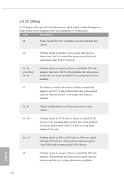
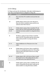
... SATA devices. Please re-install the memory and CPU. If the problem still exists, please install only one memory module or try using other memory modules. 61 - 91 Chipset initialization error. Please clear CMOS, re-install the memory and VGA card, and remove other USB, PCI devices. 01 - 54 (except 0d), 5A- 60 Problem related to PCI-E devices. Please re-install the CPU and memory. If the problem still exists, please remove all SATA devices. Please re-install IDE and SATA devices. A0 - Please press reset or clear CMOS...
... SATA devices. Please re-install the memory and CPU. If the problem still exists, please install only one memory module or try using other memory modules. 61 - 91 Chipset initialization error. Please clear CMOS, re-install the memory and VGA card, and remove other USB, PCI devices. 01 - 54 (except 0d), 5A- 60 Problem related to PCI-E devices. Please re-install the CPU and memory. If the problem still exists, please remove all SATA devices. Please re-install IDE and SATA devices. A0 - Please press reset or clear CMOS...
User Manual
Page 51
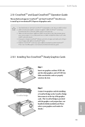
... cards will operate as 12-pipe cards while in CrossFireXTM mode. 5. Make sure that your power supply unit (PSU) can provide at least the minimum power your graphics card driver supports AMD CrossFireXTM technology. Please refer to the AMD's website for detailed installation guide. 2.10.1 Installing Two CrossFireXTM-Ready Graphics Cards Step 1 Insert one graphics card into PCIE1 slot and the other graphics card to PCIE3 slot. X470 Taichi 2.10 CrossFireXTM and Quad CrossFireXTM Operation Guide This motherboard supports...
... cards will operate as 12-pipe cards while in CrossFireXTM mode. 5. Make sure that your power supply unit (PSU) can provide at least the minimum power your graphics card driver supports AMD CrossFireXTM technology. Please refer to the AMD's website for detailed installation guide. 2.10.1 Installing Two CrossFireXTM-Ready Graphics Cards Step 1 Insert one graphics card into PCIE1 slot and the other graphics card to PCIE3 slot. X470 Taichi 2.10 CrossFireXTM and Quad CrossFireXTM Operation Guide This motherboard supports...
User Manual
Page 53
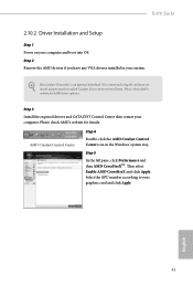
... and boot into OS. X470 Taichi 2.10.2 Driver Installation and Setup Step 1 Power on your graphics card and click Apply. We recommend using this utility to installation. Step 3 Install the required drivers and CATALYST Control Center then restart your system. AMD Catalyst Control Center Step 4 Double-click the AMD Catalyst Control Center icon in your computer. Please check AMD's website for AMD driver updates. Then select Enable AMD CrossFireX and click Apply. Step 2 Remove the AMD drivers if...
... and boot into OS. X470 Taichi 2.10.2 Driver Installation and Setup Step 1 Power on your graphics card and click Apply. We recommend using this utility to installation. Step 3 Install the required drivers and CATALYST Control Center then restart your system. AMD Catalyst Control Center Step 4 Double-click the AMD Catalyst Control Center icon in your computer. Please check AMD's website for AMD driver updates. Then select Enable AMD CrossFireX and click Apply. Step 2 Remove the AMD drivers if...
User Manual
Page 59
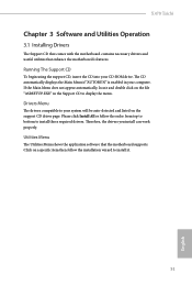
... drivers you install can work properly. X470 Taichi Chapter 3 Software and Utilities Operation 3.1 Installing Drivers The Support CD that comes with the motherboard contains necessary drivers and useful utilities that the motherboard supports. Please click Install All or follow the installation wizard to display the menu. Utilities Menu The Utilities Menu shows the application software that enhance the motherboard's features. If the Main Menu does not appear automatically, locate and double click on the file "ASRSETUP.EXE" in your CD-ROM drive...
... drivers you install can work properly. X470 Taichi Chapter 3 Software and Utilities Operation 3.1 Installing Drivers The Support CD that comes with the motherboard contains necessary drivers and useful utilities that the motherboard supports. Please click Install All or follow the installation wizard to display the menu. Utilities Menu The Utilities Menu shows the application software that enhance the motherboard's features. If the Main Menu does not appear automatically, locate and double click on the file "ASRSETUP.EXE" in your CD-ROM drive...

User Manual
Page 86
... for future selections to be used to scrub memory. SMTEN This item can be used to remove any cores, a POWER CYCLE is needed after selecting the 'Auto' option. DF Common Options DRAM scrub time Provide a value that is the number of cores to take effect. OC Mode OC1 - 16 cores/3.6GHz on 1.3375V OC2 - 8 cores/3.7GHz on 1.369V OC3 - 4 cores/3.75GHz on 1.374V\nMax Stress...
... for future selections to be used to scrub memory. SMTEN This item can be used to remove any cores, a POWER CYCLE is needed after selecting the 'Auto' option. DF Common Options DRAM scrub time Provide a value that is the number of cores to take effect. OC Mode OC1 - 16 cores/3.6GHz on 1.3375V OC2 - 8 cores/3.7GHz on 1.369V OC3 - 4 cores/3.75GHz on 1.374V\nMax Stress...
User Manual
Page 95
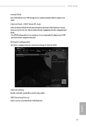
... Setting Enable or disable sound effects in your USB pen drive before using this to plug in the setup utility. DHCP (Auto IP), Auto ASRock Internet Flash downloads and updates the latest UEFI firmware version from our servers for Internet Flash. Network Configuration Use this function. UEFI Download Server Select a server to update your UEFI. Please setup network configuration before using Internet Flash. *For BIOS backup and recovery purpose, it is recommended to configure internet connection settings for you. X470 Taichi Instant Flash Save UEFI files in your USB storage...
... Setting Enable or disable sound effects in your USB pen drive before using this to plug in the setup utility. DHCP (Auto IP), Auto ASRock Internet Flash downloads and updates the latest UEFI firmware version from our servers for Internet Flash. Network Configuration Use this function. UEFI Download Server Select a server to update your UEFI. Please setup network configuration before using Internet Flash. *For BIOS backup and recovery purpose, it is recommended to configure internet connection settings for you. X470 Taichi Instant Flash Save UEFI files in your USB storage...


