
RAID Installation Guide
Page 2
.... It will improve data access and storage since the disk array management software will cause data damage or data loss. Although RAID 0 function can start to use the onboard RAID Option ROM Utility to configure RAID. 1.1 Introduction to set . For optimal performance, please install identical drives of the same model and capacity when creating a RAID set the option to RAID mode by following the detailed instruction of the "User Manual" in our support CD, then you can...
.... It will improve data access and storage since the disk array management software will cause data damage or data loss. Although RAID 0 function can start to use the onboard RAID Option ROM Utility to configure RAID. 1.1 Introduction to set . For optimal performance, please install identical drives of the same model and capacity when creating a RAID set the option to RAID mode by following the detailed instruction of the "User Manual" in our support CD, then you can...

RAID Installation Guide
Page 8
... install the DVD-ROM. Plug a USB drive into the DVD-ROM drive. E. Go to enter UEFI setup utility. During system boot, press or key to Tools Easy RAID Installer F. STEP 3.2: Download driver from ASRock's website and unzip the file into your USB flash drive. 8 B. B. During Windows installation process, when Disk selection page show up, please click . C. Insert the Support CD into one of the USB port. Please download the "SATA Floppy Imaged driver" from ASRock's website A. Click to finish the configuration. STEP 3.1: Copy RAID driver to a USB flash drive...
... install the DVD-ROM. Plug a USB drive into the DVD-ROM drive. E. Go to enter UEFI setup utility. During system boot, press or key to Tools Easy RAID Installer F. STEP 3.2: Download driver from ASRock's website and unzip the file into your USB flash drive. 8 B. B. During Windows installation process, when Disk selection page show up, please click . C. Insert the Support CD into one of the USB port. Please download the "SATA Floppy Imaged driver" from ASRock's website A. Click to finish the configuration. STEP 3.1: Copy RAID driver to a USB flash drive...

RAID Installation Guide
Page 12
... array. Click to save to finish the driver copy process. Insert the Support CD into one of the USB port. Please install the DVD-ROM. Follow instructions to exit. B. STEP 2.1: Copy RAID driver to a USB flash drive You can choose either STEP2.1 or STEP2.2 to enter UEFI setup utility. STEP 2.2: Download driver from ASRock's website and unzip the file into your USB flash disk. 12 G. H. During system boot, press or key to finish the configuration. Plug a USB drive into the DVD-ROM drive.
... array. Click to save to finish the driver copy process. Insert the Support CD into one of the USB port. Please install the DVD-ROM. Follow instructions to exit. B. STEP 2.1: Copy RAID driver to a USB flash drive You can choose either STEP2.1 or STEP2.2 to enter UEFI setup utility. STEP 2.2: Download driver from ASRock's website and unzip the file into your USB flash disk. 12 G. H. During system boot, press or key to finish the configuration. Plug a USB drive into the DVD-ROM drive.
User Manual
Page 5
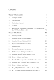
... Package Contents 1 1.2 Specifications 2 1.3 Motherboard Layout 7 1.4 I/O Panel 9 1.5 WiFi-802.11ac Module and ASRock WiFi 2.4/5 GHz Antennas (for X470 Master SLI/ac only) 12 Chapter 2 Installation 14 2.1 Installing the CPU 15 2.2 Installing the CPU Fan and Heatsink 17 2.3 Installing Memory Modules (DIMM) 26 2.4 Expansion Slots (PCI Express Slots) 29 2.5 Jumpers Setup 30 2.6 Onboard Headers and Connectors 31 2.7 SLITM and Quad SLITM Operation Guide 37 2.7.1 Installing Two SLITM-Ready Graphics Cards 37 2.7.2 Driver Installation and Setup 39 2.8 CrossFireXTM and...
... Package Contents 1 1.2 Specifications 2 1.3 Motherboard Layout 7 1.4 I/O Panel 9 1.5 WiFi-802.11ac Module and ASRock WiFi 2.4/5 GHz Antennas (for X470 Master SLI/ac only) 12 Chapter 2 Installation 14 2.1 Installing the CPU 15 2.2 Installing the CPU Fan and Heatsink 17 2.3 Installing Memory Modules (DIMM) 26 2.4 Expansion Slots (PCI Express Slots) 29 2.5 Jumpers Setup 30 2.6 Onboard Headers and Connectors 31 2.7 SLITM and Quad SLITM Operation Guide 37 2.7.1 Installing Two SLITM-Ready Graphics Cards 37 2.7.2 Driver Installation and Setup 39 2.8 CrossFireXTM and...
User Manual
Page 8
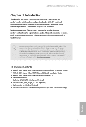
... to change without further notice. In case any modifications of this documentation, Chapter 1 and 2 contains the introduction of this motherboard, please visit our website for specific information about the model you are using. ASRock website http://www.asrock.com. 1.1 Package Contents • ASRock X470 Master SLI/ac / X470 Master SLI Motherboard (ATX Form Factor) • ASRock X470 Master SLI/ac / X470 Master SLI Quick Installation Guide • ASRock X470 Master SLI/ac / X470 Master SLI Support CD • 1 x I/O Panel Shield • 2 x Serial ATA (SATA) Data Cables (Optional...
... to change without further notice. In case any modifications of this documentation, Chapter 1 and 2 contains the introduction of this motherboard, please visit our website for specific information about the model you are using. ASRock website http://www.asrock.com. 1.1 Package Contents • ASRock X470 Master SLI/ac / X470 Master SLI Motherboard (ATX Form Factor) • ASRock X470 Master SLI/ac / X470 Master SLI Quick Installation Guide • ASRock X470 Master SLI/ac / X470 Master SLI Support CD • 1 x I/O Panel Shield • 2 x Serial ATA (SATA) Data Cables (Optional...
User Manual
Page 11
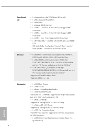
...X470 Master SLI/ac only) • 1 x PS/2 Mouse/Keyboard Port • 1 x HDMI Port • 1 x Optical SPDIF Out Port • 1 x USB 3.1 Gen2 Type-A Port (10 Gb/s) (Supports ESD Protection) • 1 x USB 3.1 Gen2 Type-C Port (10 Gb/s) (Supports ESD Protection) • 6 x USB 3.1 Gen1 Ports (Supports ESD Protection) • 1 x RJ-45 LAN Port with LED (ACT/LINK LED and SPEED LED) • HD Audio Jacks: Rear Speaker / Central / Bass / Line in / Front Speaker / Microphone (Gold Audio Jacks) Storage • 6 x SATA3 6.0 Gb/s Connectors, support RAID (RAID 0, RAID 1 and RAID 10), NCQ, AHCI...
...X470 Master SLI/ac only) • 1 x PS/2 Mouse/Keyboard Port • 1 x HDMI Port • 1 x Optical SPDIF Out Port • 1 x USB 3.1 Gen2 Type-A Port (10 Gb/s) (Supports ESD Protection) • 1 x USB 3.1 Gen2 Type-C Port (10 Gb/s) (Supports ESD Protection) • 6 x USB 3.1 Gen1 Ports (Supports ESD Protection) • 1 x RJ-45 LAN Port with LED (ACT/LINK LED and SPEED LED) • HD Audio Jacks: Rear Speaker / Central / Bass / Line in / Front Speaker / Microphone (Gold Audio Jacks) Storage • 6 x SATA3 6.0 Gb/s Connectors, support RAID (RAID 0, RAID 1 and RAID 10), NCQ, AHCI...

User Manual
Page 15
... Power Connector (ATX12V2) 3 CPU Fan Connector (CPU_FAN1) 4 CPU/Water Pump Fan Connector (CPU_FAN2/WP) 5 2 x 288-pin DDR4 DIMM Slots (DDR4_A1, DDR4_B1) 6 2 x 288-pin DDR4 DIMM Slots (DDR4_A2, DDR4_B2) 7 ATX Power Connector (ATXPWR1) 8 USB 3.1 Gen1 Header (USB3_9_10) 9 USB 3.1 Gen1 Header (USB3_7_8) 10 AMD LED Fan USB Header (USB_5) 11 AMD Fan LED Header (AMD_FAN_LED1) 12 Chassis/Water Pump Fan Connector (CHA_FAN1/WP) 13 SATA3 Connectors (SATA3_5_6) 14 SATA3 Connectors (SATA3_3_4) 15 SATA3 Connectors (SATA3_1_2) 16 System Panel Header (PANEL1) 17 RGB LED Header (RGB_LED1) 18 Clear CMOS Jumper...
... Power Connector (ATX12V2) 3 CPU Fan Connector (CPU_FAN1) 4 CPU/Water Pump Fan Connector (CPU_FAN2/WP) 5 2 x 288-pin DDR4 DIMM Slots (DDR4_A1, DDR4_B1) 6 2 x 288-pin DDR4 DIMM Slots (DDR4_A2, DDR4_B2) 7 ATX Power Connector (ATXPWR1) 8 USB 3.1 Gen1 Header (USB3_9_10) 9 USB 3.1 Gen1 Header (USB3_7_8) 10 AMD LED Fan USB Header (USB_5) 11 AMD Fan LED Header (AMD_FAN_LED1) 12 Chassis/Water Pump Fan Connector (CHA_FAN1/WP) 13 SATA3 Connectors (SATA3_5_6) 14 SATA3 Connectors (SATA3_3_4) 15 SATA3 Connectors (SATA3_1_2) 16 System Panel Header (PANEL1) 17 RGB LED Header (RGB_LED1) 18 Clear CMOS Jumper...

User Manual
Page 32
If you select AMD_FAN_LED1, please install ASRock utility "ASRock Polychrome RGB". X470 Master SLI/ac / X470 Master SLI 6 CPU_FAN1 +12V AMD_FAN_LED1 or 7 CPU_FAN1 AMD_FAN_LED1 USB_5 Please note that only one cable should be used at a time in this step. If you select USB connector, please install AMD utility "SR3 Settings Software". *The diagram shown here are for the orientation of AMD LED Fan USB Header (USB_5). 25 English Please refer to page 35 for the orientation of AMD Fan LED Header (AMD_FAN_LED1) and page 32 for reference only.
If you select AMD_FAN_LED1, please install ASRock utility "ASRock Polychrome RGB". X470 Master SLI/ac / X470 Master SLI 6 CPU_FAN1 +12V AMD_FAN_LED1 or 7 CPU_FAN1 AMD_FAN_LED1 USB_5 Please note that only one cable should be used at a time in this step. If you select USB connector, please install AMD utility "SR3 Settings Software". *The diagram shown here are for the orientation of AMD LED Fan USB Header (USB_5). 25 English Please refer to page 35 for the orientation of AMD Fan LED Header (AMD_FAN_LED1) and page 32 for reference only.

User Manual
Page 39
... chassis speaker to 6.0 Gb/s data transfer rate. SATA3_1 SATA3_3 SATA3_5 SATA3_2 SATA3_4 SATA3_6 AMD LED Fan USB Header (4-pin USB_5) (see p.7, No. 10) USB 2.0 Headers ((9-pin USB_1_2) (see p.7, No. 22) (9-pin USB_3_4) (see p.7, No. 13) SPEAKER DUMMY DUMMY +5V 1 PLED+ PLED+ PLED- Each USB 2.0 header can support two ports. Each USB 3.1 Gen1 header can support two ports. P+ USB_PWR This header is used for internal storage devices with up to this motherboard. These six SATA3 connectors support SATA data cables for connecting the USB connector...
... chassis speaker to 6.0 Gb/s data transfer rate. SATA3_1 SATA3_3 SATA3_5 SATA3_2 SATA3_4 SATA3_6 AMD LED Fan USB Header (4-pin USB_5) (see p.7, No. 10) USB 2.0 Headers ((9-pin USB_1_2) (see p.7, No. 22) (9-pin USB_3_4) (see p.7, No. 13) SPEAKER DUMMY DUMMY +5V 1 PLED+ PLED+ PLED- Each USB 2.0 header can support two ports. Each USB 3.1 Gen1 header can support two ports. P+ USB_PWR This header is used for internal storage devices with up to this motherboard. These six SATA3 connectors support SATA data cables for connecting the USB connector...
User Manual
Page 47
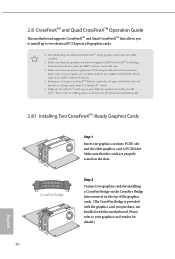
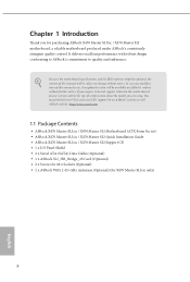
... AMD graphics card manuals for details.) English 40 Make sure that your power supply unit (PSU) can provide at least the minimum power your graphics card driver supports AMD CrossFireXTM technology. Make sure that the cards are AMD certified. 2. 2.8 CrossFireXTM and Quad CrossFireXTM Operation Guide This motherboard supports CrossFireXTM and Quad CrossFireXTM that allows you to install up to PCIE4 slot. Please refer to enable CrossFireXTM. Download the drivers from the AMD's website: www.amd...
... AMD graphics card manuals for details.) English 40 Make sure that your power supply unit (PSU) can provide at least the minimum power your graphics card driver supports AMD CrossFireXTM technology. Make sure that the cards are AMD certified. 2. 2.8 CrossFireXTM and Quad CrossFireXTM Operation Guide This motherboard supports CrossFireXTM and Quad CrossFireXTM that allows you to install up to PCIE4 slot. Please refer to enable CrossFireXTM. Download the drivers from the AMD's website: www.amd...

User Manual
Page 49
... an optional download. Please check AMD's website for AMD driver updates. Select the GPU number according to installation. AMD Catalyst Control Center Step 4 Double-click the AMD Catalyst Control Center icon in your graphics card and click Apply. English 42 Step 5 In the left pane, click Performance and then AMD CrossFireXTM. Please check AMD's website for details. 2.8.2 Driver Installation and Setup Step 1 Power on your computer. We recommend using this utility...
... an optional download. Please check AMD's website for AMD driver updates. Select the GPU number according to installation. AMD Catalyst Control Center Step 4 Double-click the AMD Catalyst Control Center icon in your graphics card and click Apply. English 42 Step 5 In the left pane, click Performance and then AMD CrossFireXTM. Please check AMD's website for details. 2.8.2 Driver Installation and Setup Step 1 Power on your computer. We recommend using this utility...

User Manual
Page 56
..., locate and double click on a specific item then follow the order from top to bottom to your system will be auto-detected and listed on the support CD driver page. Click on the file "ASRSETUP.EXE" in your CD-ROM drive. The CD automatically displays the Main Menu if "AUTORUN" is enabled in the Support CD to install it. 49 English X470 Master SLI/ac / X470 Master SLI Chapter 3 Software and Utilities Operation 3.1 Installing Drivers The Support...
..., locate and double click on a specific item then follow the order from top to bottom to your system will be auto-detected and listed on the support CD driver page. Click on the file "ASRSETUP.EXE" in your CD-ROM drive. The CD automatically displays the Main Menu if "AUTORUN" is enabled in the Support CD to install it. 49 English X470 Master SLI/ac / X470 Master SLI Chapter 3 Software and Utilities Operation 3.1 Installing Drivers The Support...

User Manual
Page 80
X470 Master SLI/ac / X470 Master SLI 4.4.5 Super IO Configuration Serial Port Enable or disable the Serial port. Serial Port Address Select the address of the Serial port. PS2 Y-Cable Enable the PS2 Y-Cable or set this option to Auto. 73 English
X470 Master SLI/ac / X470 Master SLI 4.4.5 Super IO Configuration Serial Port Enable or disable the Serial port. Serial Port Address Select the address of the Serial port. PS2 Y-Cable Enable the PS2 Y-Cable or set this option to Auto. 73 English

User Manual
Page 84
X470 Master SLI/ac / X470 Master SLI Opcache Control Enables or disables the Opcache. Core/Thread Enablement Downcore control Sets the number of hours to scrub memory. Freeze DF module queues on error Controls DF::PIEConfig[DisImmSyncFloodOnFatalError] Disabling this field are from 0x1 (1) - 0x10 (16). To re-enable SMT, a POWER CYCLE is NOT SUPPORTED on 1.400V SEV-ES ASID Space Limit SEV VMs using ASIDs below the SEV-ES ASID Space Limit must...
X470 Master SLI/ac / X470 Master SLI Opcache Control Enables or disables the Opcache. Core/Thread Enablement Downcore control Sets the number of hours to scrub memory. Freeze DF module queues on error Controls DF::PIEConfig[DisImmSyncFloodOnFatalError] Disabling this field are from 0x1 (1) - 0x10 (16). To re-enable SMT, a POWER CYCLE is NOT SUPPORTED on 1.400V SEV-ES ASID Space Limit SEV VMs using ASIDs below the SEV-ES ASID Space Limit must...

User Manual
Page 92
After copying the drivers please change the SATA mode to RAID, then you to adjust the RGB LED color to your liking. 4.5 Tools X470 Master SLI/ac / X470 Master SLI RGB LED ASRock RGB LED allows you can start installing the operating system in RAID mode. 85 English Easy RAID Installer Easy RAID Installer helps you to copy the RAID driver from the support CD to your USB storage device.
After copying the drivers please change the SATA mode to RAID, then you to adjust the RGB LED color to your liking. 4.5 Tools X470 Master SLI/ac / X470 Master SLI RGB LED ASRock RGB LED allows you can start installing the operating system in RAID mode. 85 English Easy RAID Installer Easy RAID Installer helps you to copy the RAID driver from the support CD to your USB storage device.

User Manual
Page 93
Internet Setting Enable or disable sound effects in your USB storage device and run Instant Flash to download the UEFI firmware. 86 English Instant Flash Save UEFI files in the setup utility. UEFI Download Server Select a server to update your UEFI. Network Configuration Use this to configure internet connection settings for Internet Flash.
Internet Setting Enable or disable sound effects in your USB storage device and run Instant Flash to download the UEFI firmware. 86 English Instant Flash Save UEFI files in the setup utility. UEFI Download Server Select a server to update your UEFI. Network Configuration Use this to configure internet connection settings for Internet Flash.

Quick Installation Guide
Page 6
... Power Connector (ATX12V2) 3 CPU Fan Connector (CPU_FAN1) 4 CPU/Water Pump Fan Connector (CPU_FAN2/WP) 5 2 x 288-pin DDR4 DIMM Slots (DDR4_A1, DDR4_B1) 6 2 x 288-pin DDR4 DIMM Slots (DDR4_A2, DDR4_B2) 7 ATX Power Connector (ATXPWR1) 8 USB 3.1 Gen1 Header (USB3_9_10) 9 USB 3.1 Gen1 Header (USB3_7_8) 10 AMD LED Fan USB Header (USB_5) 11 AMD Fan LED Header (AMD_FAN_LED1) 12 Chassis/Water Pump Fan Connector (CHA_FAN1/WP) 13 SATA3 Connectors (SATA3_5_6) 14 SATA3 Connectors (SATA3_3_4) 15 SATA3 Connectors (SATA3_1_2) 16 System Panel Header (PANEL1) 17 RGB LED Header (RGB_LED1) 18 Clear CMOS Jumper...
... Power Connector (ATX12V2) 3 CPU Fan Connector (CPU_FAN1) 4 CPU/Water Pump Fan Connector (CPU_FAN2/WP) 5 2 x 288-pin DDR4 DIMM Slots (DDR4_A1, DDR4_B1) 6 2 x 288-pin DDR4 DIMM Slots (DDR4_A2, DDR4_B2) 7 ATX Power Connector (ATXPWR1) 8 USB 3.1 Gen1 Header (USB3_9_10) 9 USB 3.1 Gen1 Header (USB3_7_8) 10 AMD LED Fan USB Header (USB_5) 11 AMD Fan LED Header (AMD_FAN_LED1) 12 Chassis/Water Pump Fan Connector (CHA_FAN1/WP) 13 SATA3 Connectors (SATA3_5_6) 14 SATA3 Connectors (SATA3_3_4) 15 SATA3 Connectors (SATA3_1_2) 16 System Panel Header (PANEL1) 17 RGB LED Header (RGB_LED1) 18 Clear CMOS Jumper...
Quick Installation Guide
Page 12
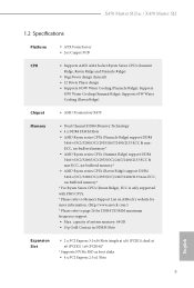
... X470 Master SLI Quick Installation Guide • ASRock X470 Master SLI/ac / X470 Master SLI Support CD • 1 x I/O Panel Shield • 2 x Serial ATA (SATA) Data Cables (Optional) • 1 x ASRock SLI_HB_Bridge_2S Card (Optional) • 2 x Screws for M.2 Sockets (Optional) • 2 x ASRock WiFi 2.4/5 GHz Antennas (Optional) (for purchasing ASRock X470 Master SLI/ac / X470 Master SLI motherboard, a reliable motherboard produced under ASRock's consistently stringent quality control. Chapter 1 Introduction Thank you are using. Because the motherboard specifications and the BIOS...
... X470 Master SLI Quick Installation Guide • ASRock X470 Master SLI/ac / X470 Master SLI Support CD • 1 x I/O Panel Shield • 2 x Serial ATA (SATA) Data Cables (Optional) • 1 x ASRock SLI_HB_Bridge_2S Card (Optional) • 2 x Screws for M.2 Sockets (Optional) • 2 x ASRock WiFi 2.4/5 GHz Antennas (Optional) (for purchasing ASRock X470 Master SLI/ac / X470 Master SLI motherboard, a reliable motherboard produced under ASRock's consistently stringent quality control. Chapter 1 Introduction Thank you are using. Because the motherboard specifications and the BIOS...
Quick Installation Guide
Page 13
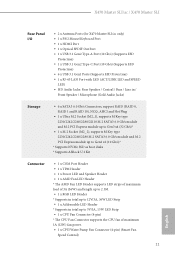
dual at x16 (PCIE1); X470 Master SLI/ac / X470 Master SLI 1.2 Specifications Platform • ATX Form Factor • 2oz Copper PCB CPU • Supports AMD AM4 Socket Ryzen Series CPUs (Summit Ridge, Raven Ridge and Pinnacle Ridge) • Digi Power design (Intersil) • 12 Power Phase design • Supports 105W Water Cooling (Pinnacle Ridge); capacity of system memory: 64GB • 15μ Gold Contact in DIMM Slots Expansion Slot • 2 x PCI Express 3.0 x16 Slots (single...
dual at x16 (PCIE1); X470 Master SLI/ac / X470 Master SLI 1.2 Specifications Platform • ATX Form Factor • 2oz Copper PCB CPU • Supports AMD AM4 Socket Ryzen Series CPUs (Summit Ridge, Raven Ridge and Pinnacle Ridge) • Digi Power design (Intersil) • 12 Power Phase design • Supports 105W Water Cooling (Pinnacle Ridge); capacity of system memory: 64GB • 15μ Gold Contact in DIMM Slots Expansion Slot • 2 x PCI Express 3.0 x16 Slots (single...
Quick Installation Guide
Page 15
...X470 Master SLI/ac only) • 1 x PS/2 Mouse/Keyboard Port • 1 x HDMI Port • 1 x Optical SPDIF Out Port • 1 x USB 3.1 Gen2 Type-A Port (10 Gb/s) (Supports ESD Protection) • 1 x USB 3.1 Gen2 Type-C Port (10 Gb/s) (Supports ESD Protection) • 6 x USB 3.1 Gen1 Ports (Supports ESD Protection) • 1 x RJ-45 LAN Port with LED (ACT/LINK LED and SPEED LED) • HD Audio Jacks: Rear Speaker / Central / Bass / Line in / Front Speaker / Microphone (Gold Audio Jacks) Storage • 6 x SATA3 6.0 Gb/s Connectors, support RAID (RAID 0, RAID 1 and RAID 10), NCQ, AHCI...
...X470 Master SLI/ac only) • 1 x PS/2 Mouse/Keyboard Port • 1 x HDMI Port • 1 x Optical SPDIF Out Port • 1 x USB 3.1 Gen2 Type-A Port (10 Gb/s) (Supports ESD Protection) • 1 x USB 3.1 Gen2 Type-C Port (10 Gb/s) (Supports ESD Protection) • 6 x USB 3.1 Gen1 Ports (Supports ESD Protection) • 1 x RJ-45 LAN Port with LED (ACT/LINK LED and SPEED LED) • HD Audio Jacks: Rear Speaker / Central / Bass / Line in / Front Speaker / Microphone (Gold Audio Jacks) Storage • 6 x SATA3 6.0 Gb/s Connectors, support RAID (RAID 0, RAID 1 and RAID 10), NCQ, AHCI...


