

RAID Installation Guide
Page 2
... "User Manual" in our support CD, then you make a SATA driver diskette, press or to enter BIOS setup to configure RAID functions by following the detailed instruction of data from one logical unit. Although RAID 0 function can start to use the onboard RAID Option ROM Utility to configure RAID. 1.1 Introduction to RAID The term "RAID" stands for "Redundant Array of Independent Disks", which is an instruction for you to set . AMD BIOS RAID Installation Guide AMD BIOS RAID Installation Guide is a method combining two or more hard disk drives...
... "User Manual" in our support CD, then you make a SATA driver diskette, press or to enter BIOS setup to configure RAID functions by following the detailed instruction of data from one logical unit. Although RAID 0 function can start to use the onboard RAID Option ROM Utility to configure RAID. 1.1 Introduction to RAID The term "RAID" stands for "Redundant Array of Independent Disks", which is an instruction for you to set . AMD BIOS RAID Installation Guide AMD BIOS RAID Installation Guide is a method combining two or more hard disk drives...

RAID Installation Guide
Page 8
Plug a USB drive into the DVD-ROM drive. Follow instructions to enter UEFI setup utility. STEP 3.2: Download driver from ASRock's website and unzip the file into your USB flash drive. 8 During system boot, press or key to finish the driver copy process. C. E. Go to finish the configuration. STEP 4: Windows installation A. STEP 3.1: Copy RAID driver to a USB flash drive You can choose either STEP 3.1 or STEP 3.2 to Tools Easy RAID Installer F. Click to find the driver inside your USB flash disk. A. D. B. Please download the "SATA Floppy Imaged driver...
Plug a USB drive into the DVD-ROM drive. Follow instructions to enter UEFI setup utility. STEP 3.2: Download driver from ASRock's website and unzip the file into your USB flash drive. 8 During system boot, press or key to finish the driver copy process. C. E. Go to finish the configuration. STEP 4: Windows installation A. STEP 3.1: Copy RAID driver to a USB flash drive You can choose either STEP 3.1 or STEP 3.2 to Tools Easy RAID Installer F. Click to find the driver inside your USB flash disk. A. D. B. Please download the "SATA Floppy Imaged driver...

RAID Installation Guide
Page 12
... RAID driver to a USB flash drive You can choose either STEP2.1 or STEP2.2 to enter UEFI setup utility. Plug a USB drive into the DVD-ROM drive. During system boot, press or key to finish the configuration. STEP 2.2: Download driver from ASRock's website and unzip the file into your USB flash disk. 12 Please install the DVD-ROM. D. C. Insert the Support CD into one of the USB port. Click to save to finish the driver copy process. B. E. G. Please download the "SATA Floppy Imaged driver" from ASRock's website A. Follow instructions...
... RAID driver to a USB flash drive You can choose either STEP2.1 or STEP2.2 to enter UEFI setup utility. Plug a USB drive into the DVD-ROM drive. During system boot, press or key to finish the configuration. STEP 2.2: Download driver from ASRock's website and unzip the file into your USB flash disk. 12 Please install the DVD-ROM. D. C. Insert the Support CD into one of the USB port. Click to save to finish the driver copy process. B. E. G. Please download the "SATA Floppy Imaged driver" from ASRock's website A. Follow instructions...

User Manual
Page 4
... Introduction 1 1.1 Package Contents 1 1.2 Specifications 2 1.3 Motherboard Layout 6 1.4 I/O Panel 8 Chapter 2 Installation 10 2.1 Installing the CPU 11 2.2 Installing the CPU Fan and Heatsink 13 2.3 Installing Memory Modules (DIMM) 21 2.4 Expansion Slots (PCI Express Slots) 24 2.5 Jumpers Setup 25 2.6 Onboard Headers and Connectors 26 2.7 M.2_SSD (NGFF) Module Installation Guide 30 Chapter 3 Software and Utilities Operation 34 3.1 Installing Drivers 34 3.2 A-Tuning 35 3.2.1 Installing A-Tuning 35 3.2.2 Using A-Tuning 35 3.3 ASRock Live Update & APP Shop 38...
... Introduction 1 1.1 Package Contents 1 1.2 Specifications 2 1.3 Motherboard Layout 6 1.4 I/O Panel 8 Chapter 2 Installation 10 2.1 Installing the CPU 11 2.2 Installing the CPU Fan and Heatsink 13 2.3 Installing Memory Modules (DIMM) 21 2.4 Expansion Slots (PCI Express Slots) 24 2.5 Jumpers Setup 25 2.6 Onboard Headers and Connectors 26 2.7 M.2_SSD (NGFF) Module Installation Guide 30 Chapter 3 Software and Utilities Operation 34 3.1 Installing Drivers 34 3.2 A-Tuning 35 3.2.1 Installing A-Tuning 35 3.2.2 Using A-Tuning 35 3.3 ASRock Live Update & APP Shop 38...
User Manual
Page 6
... manual occur, the updated version will be available on ASRock's website as well. If you for M.2 Socket (Optional) • 1 x I/O Panel Shield 1 English Chapter 3 contains the operation guide of this manual will be subject to change without further notice. ASRock website http://www.asrock.com. 1.1 Package Contents • ASRock X370M-HDV Motherboard (Micro ATX Form Factor) • ASRock X370M-HDV Quick Installation Guide • ASRock X370M-HDV Support CD • 2 x Serial ATA (SATA) Data Cables (Optional) • 1 x Screw for purchasing ASRock X370M-HDV motherboard...
... manual occur, the updated version will be available on ASRock's website as well. If you for M.2 Socket (Optional) • 1 x I/O Panel Shield 1 English Chapter 3 contains the operation guide of this manual will be subject to change without further notice. ASRock website http://www.asrock.com. 1.1 Package Contents • ASRock X370M-HDV Motherboard (Micro ATX Form Factor) • ASRock X370M-HDV Quick Installation Guide • ASRock X370M-HDV Support CD • 2 x Serial ATA (SATA) Data Cables (Optional) • 1 x Screw for purchasing ASRock X370M-HDV motherboard...

User Manual
Page 9
.../s Connectors, support RAID (RAID 0, RAID 1 and RAID 10), NCQ, AHCI and Hot Plug • 1 x Ultra M.2 Socket, supports M Key type 2242/2260/2280 M.2 SATA3 6.0 Gb/s module and M.2 PCI Express module up to Gen3 x4 (32 Gb/s) (with Summit Ridge, Raven Ridge and Pinnacle Ridge) or Gen3 x2 (16 Gb/s) (with A-Series APU)* * Supports NVMe SSD as boot disks * Supports ASRock U.2 Kit Connector • 1 x Print Port Header • 1 x COM Port Header • 1 x TPM Header • 1 x Chassis Intrusion and Speaker Header • 1 x CPU Fan Connector (4-pin...
.../s Connectors, support RAID (RAID 0, RAID 1 and RAID 10), NCQ, AHCI and Hot Plug • 1 x Ultra M.2 Socket, supports M Key type 2242/2260/2280 M.2 SATA3 6.0 Gb/s module and M.2 PCI Express module up to Gen3 x4 (32 Gb/s) (with Summit Ridge, Raven Ridge and Pinnacle Ridge) or Gen3 x2 (16 Gb/s) (with A-Series APU)* * Supports NVMe SSD as boot disks * Supports ASRock U.2 Kit Connector • 1 x Print Port Header • 1 x COM Port Header • 1 x TPM Header • 1 x Chassis Intrusion and Speaker Header • 1 x CPU Fan Connector (4-pin...
User Manual
Page 10
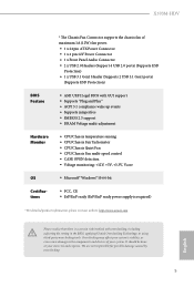
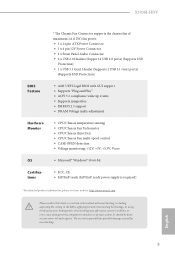
... and devices of maximum 1A (12W) fan power. • 1 x 24 pin ATX Power Connector • 1 x 4 pin 12V Power Connector • 1 x Front Panel Audio Connector • 2 x USB 2.0 Headers (Support 4 USB 2.0 ports) (Supports ESD Protection) • 1 x USB 3.1 Gen1 Header (Supports 2 USB 3.1 Gen1 ports) (Supports ESD Protection) BIOS Feature • AMI UEFI Legal BIOS with GUI support • Supports "Plug and Play" • ACPI 5.1 compliance wake up events • Supports jumperfree • SMBIOS 2.3 support • DRAM Voltage multi-adjustment Hardware Monitor • CPU/Chassis...
... and devices of maximum 1A (12W) fan power. • 1 x 24 pin ATX Power Connector • 1 x 4 pin 12V Power Connector • 1 x Front Panel Audio Connector • 2 x USB 2.0 Headers (Support 4 USB 2.0 ports) (Supports ESD Protection) • 1 x USB 3.1 Gen1 Header (Supports 2 USB 3.1 Gen1 ports) (Supports ESD Protection) BIOS Feature • AMI UEFI Legal BIOS with GUI support • Supports "Plug and Play" • ACPI 5.1 compliance wake up events • Supports jumperfree • SMBIOS 2.3 support • DRAM Voltage multi-adjustment Hardware Monitor • CPU/Chassis...

User Manual
Page 11
1.3 Motherboard Layout PS2 Keyboard/ Mouse USB 2.0 T: USB1 B: USB2 ATX12V CPU_FAN1 RoHS DDR4_A1 (64 bit, 288-FpinSBmo8d0ul0e) DDR4_B1 (64 bit, 288-pin module) ATXPWR1 SOCKET AM4 HDMI1 USB 3.1 Gen1 T: USB1 B: USB2 RJ-45 LAN Top: LINE IN Center: FRONT Bottom: MIC IN USB 3.1 Gen1 T: USB3 B: USB4 CMOS Battery CHA_FAN1/WP 1 TPMS1 BIOS ROM X370M-HDV USB3_5_6 1 PCIE1 M2_1 LAN AUDIO CODEC HD_AUDIO1 1 1 COM1 PCIE2 Super I/O CLRCMOS1 1 LPT1 1 CHA_FAN2 SPK_CI1 1 PLED PWRBTN...
1.3 Motherboard Layout PS2 Keyboard/ Mouse USB 2.0 T: USB1 B: USB2 ATX12V CPU_FAN1 RoHS DDR4_A1 (64 bit, 288-FpinSBmo8d0ul0e) DDR4_B1 (64 bit, 288-pin module) ATXPWR1 SOCKET AM4 HDMI1 USB 3.1 Gen1 T: USB1 B: USB2 RJ-45 LAN Top: LINE IN Center: FRONT Bottom: MIC IN USB 3.1 Gen1 T: USB3 B: USB4 CMOS Battery CHA_FAN1/WP 1 TPMS1 BIOS ROM X370M-HDV USB3_5_6 1 PCIE1 M2_1 LAN AUDIO CODEC HD_AUDIO1 1 1 COM1 PCIE2 Super I/O CLRCMOS1 1 LPT1 1 CHA_FAN2 SPK_CI1 1 PLED PWRBTN...

User Manual
Page 12
...12V Power Connector (ATX12V1) 2 CPU Fan Connector (CPU_FAN1) 3 2 x 288-pin DDR4 DIMM Slots (DDR4_A1, DDR4_B1) 4 ATX Power Connector (ATXPWR1) 5 USB 3.1 Gen1 Header (USB3_5_6) 6 USB 2.0 Header (USB_3_4) 7 USB 2.0 Header (USB_5_6) 8 SATA3 Connector (SATA3_3) 9 SATA3 Connector (SATA3_4) 10 SATA3 Connector (SATA3_1) 11 SATA3 Connector (SATA3_2) 12 Clear CMOS Jumper (CLRCMOS1) 13 System Panel Header (PANEL1) 14 Chassis Intrusion and Speaker Header (SPK_CI1) 15 Chassis Fan Connector (CHA_FAN2) 16 Print Port Header (LPT1) 17 COM Port Header (COM1) 18 Front Panel Audio Header (HD_AUDIO1) 19 TPM Header...
...12V Power Connector (ATX12V1) 2 CPU Fan Connector (CPU_FAN1) 3 2 x 288-pin DDR4 DIMM Slots (DDR4_A1, DDR4_B1) 4 ATX Power Connector (ATXPWR1) 5 USB 3.1 Gen1 Header (USB3_5_6) 6 USB 2.0 Header (USB_3_4) 7 USB 2.0 Header (USB_5_6) 8 SATA3 Connector (SATA3_3) 9 SATA3 Connector (SATA3_4) 10 SATA3 Connector (SATA3_1) 11 SATA3 Connector (SATA3_2) 12 Clear CMOS Jumper (CLRCMOS1) 13 System Panel Header (PANEL1) 14 Chassis Intrusion and Speaker Header (SPK_CI1) 15 Chassis Fan Connector (CHA_FAN2) 16 Print Port Header (LPT1) 17 COM Port Header (COM1) 18 Front Panel Audio Header (HD_AUDIO1) 19 TPM Header...

User Manual
Page 30
... shows a 3-pin jumper whose pin1 and pin2 are setup. Please adjust the BIOS option "Clear Status" to default setup, please turn off the computer and unplug the power cord from the power supply. X370M-HDV 2.5 Jumpers Setup The illustration shows how jumpers are "Short" when a jumper cap is placed on these 2 pins. Please be noted that the password, date, time, and user default profile will be detected. If you do not clear the CMOS right...
... shows a 3-pin jumper whose pin1 and pin2 are setup. Please adjust the BIOS option "Clear Status" to default setup, please turn off the computer and unplug the power cord from the power supply. X370M-HDV 2.5 Jumpers Setup The illustration shows how jumpers are "Short" when a jumper cap is placed on these 2 pins. Please be noted that the password, date, time, and user default profile will be detected. If you do not clear the CMOS right...
User Manual
Page 39
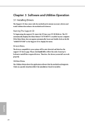
... be auto-detected and listed on the support CD driver page. If the Main Menu does not appear automatically, locate and double click on a specific item then follow the order from top to bottom to install it. 34 English Utilities Menu The Utilities Menu shows the application software that enhance the motherboard's features. Therefore, the drivers you install can work properly. Drivers Menu The drivers compatible to display the menu. Click on the file "ASRSETUP...
... be auto-detected and listed on the support CD driver page. If the Main Menu does not appear automatically, locate and double click on a specific item then follow the order from top to bottom to install it. 34 English Utilities Menu The Utilities Menu shows the application software that enhance the motherboard's features. Therefore, the drivers you install can work properly. Drivers Menu The drivers compatible to display the menu. Click on the file "ASRSETUP...

User Manual
Page 55
... enable or disable AMD CPU fTPM. AMD fTPM Switch Use this function may reduce CPU voltage and memory frequency, and lead to system stability or compatibility issue with some memory modules or power supplies. If you install Windows® OS and want to enable this function, please set to [Enabled], a VMM (Virtual Machine Architecture) can utilize the additional hardware capabilities provided by AMD-V. The default value is [Enabled]. 4.4.1 CPU Configuration Cool 'n' Quiet Use this item to [Enabled]. Configuration options: [Enabled] and [Disabled]. The default...
... enable or disable AMD CPU fTPM. AMD fTPM Switch Use this function may reduce CPU voltage and memory frequency, and lead to system stability or compatibility issue with some memory modules or power supplies. If you install Windows® OS and want to enable this function, please set to [Enabled], a VMM (Virtual Machine Architecture) can utilize the additional hardware capabilities provided by AMD-V. The default value is [Enabled]. 4.4.1 CPU Configuration Cool 'n' Quiet Use this item to [Enabled]. Configuration options: [Enabled] and [Disabled]. The default...

User Manual
Page 59
4.4.5 Super IO Configuration Serial Port Enable or disable the Serial port. Parallel Port Enable or disable the Parallel port. PS2 Y-Cable Enable the PS2 Y-Cable or set this option to your connected device. Device Mode Select the device mode according to Auto. 54 English Serial Port Address Select the address of the Parallel port. Change Settings Select the address of the Serial port.
4.4.5 Super IO Configuration Serial Port Enable or disable the Serial port. Parallel Port Enable or disable the Parallel port. PS2 Y-Cable Enable the PS2 Y-Cable or set this option to your connected device. Device Mode Select the device mode according to Auto. 54 English Serial Port Address Select the address of the Parallel port. Change Settings Select the address of the Serial port.

User Manual
Page 63
...-ES ASID Space Limit must enable the SEV-ES feature. Core/Thread Enablement Downcore control Sets the number of hours to scrub memory. DF Common Options DRAM scrub time Provide a value that is required in order for this option has been used to remove any cores, a POWER CYCLE is the number of cores to be used . Redirect scrubber control Control DF::RedirScrubCtrl[EnRedirScrub] Disable DF sync flood propagation...
...-ES ASID Space Limit must enable the SEV-ES feature. Core/Thread Enablement Downcore control Sets the number of hours to scrub memory. DF Common Options DRAM scrub time Provide a value that is required in order for this option has been used to remove any cores, a POWER CYCLE is the number of cores to be used . Redirect scrubber control Control DF::RedirScrubCtrl[EnRedirScrub] Disable DF sync flood propagation...

User Manual
Page 64
...'t support the selected option. The valid values are hashed during channel interleave mode. Note that distributed requires memory on parts where the probe filter is fuse disabled. Channel interleaving hash Controls whether or not the address bits are AUTO, 256 bytes, 512 bytes, 1 Kbytes or 2Kbytes. Has no effect on all dies. X370M-HDV GMI encryption control GMI encryption control Control GMI link encryption xGMI encryption control Control...
...'t support the selected option. The valid values are hashed during channel interleave mode. Note that distributed requires memory on parts where the probe filter is fuse disabled. Channel interleaving hash Controls whether or not the address bits are AUTO, 256 bytes, 512 bytes, 1 Kbytes or 2Kbytes. Has no effect on all dies. X370M-HDV GMI encryption control GMI encryption control Control GMI link encryption xGMI encryption control Control...

User Manual
Page 72
English 67 UEFI Download Server Select a server to configure internet connection settings for Internet Flash. X370M-HDV Internet Setting Enable or disable sound effects in the setup utility. Network Configuration Use this to download the UEFI firmware.
English 67 UEFI Download Server Select a server to configure internet connection settings for Internet Flash. X370M-HDV Internet Setting Enable or disable sound effects in the setup utility. Network Configuration Use this to download the UEFI firmware.

Quick Installation Guide
Page 4
...12V Power Connector (ATX12V1) 2 CPU Fan Connector (CPU_FAN1) 3 2 x 288-pin DDR4 DIMM Slots (DDR4_A1, DDR4_B1) 4 ATX Power Connector (ATXPWR1) 5 USB 3.1 Gen1 Header (USB3_5_6) 6 USB 2.0 Header (USB_3_4) 7 USB 2.0 Header (USB_5_6) 8 SATA3 Connector (SATA3_3) 9 SATA3 Connector (SATA3_4) 10 SATA3 Connector (SATA3_1) 11 SATA3 Connector (SATA3_2) 12 Clear CMOS Jumper (CLRCMOS1) 13 System Panel Header (PANEL1) 14 Chassis Intrusion and Speaker Header (SPK_CI1) 15 Chassis Fan Connector (CHA_FAN2) 16 Print Port Header (LPT1) 17 COM Port Header (COM1) 18 Front Panel Audio Header (HD_AUDIO1) 19 TPM Header...
...12V Power Connector (ATX12V1) 2 CPU Fan Connector (CPU_FAN1) 3 2 x 288-pin DDR4 DIMM Slots (DDR4_A1, DDR4_B1) 4 ATX Power Connector (ATXPWR1) 5 USB 3.1 Gen1 Header (USB3_5_6) 6 USB 2.0 Header (USB_3_4) 7 USB 2.0 Header (USB_5_6) 8 SATA3 Connector (SATA3_3) 9 SATA3 Connector (SATA3_4) 10 SATA3 Connector (SATA3_1) 11 SATA3 Connector (SATA3_2) 12 Clear CMOS Jumper (CLRCMOS1) 13 System Panel Header (PANEL1) 14 Chassis Intrusion and Speaker Header (SPK_CI1) 15 Chassis Fan Connector (CHA_FAN2) 16 Print Port Header (LPT1) 17 COM Port Header (COM1) 18 Front Panel Audio Header (HD_AUDIO1) 19 TPM Header...
Quick Installation Guide
Page 7
... the latest VGA cards and CPU support list on ASRock's website without notice. Because the motherboard specifications and the BIOS software might be updated, the content of this motherboard, please visit our website for specific information about the model you for M.2 Socket (Optional) • 1 x I/O Panel Shield 5 English ASRock website http://www.asrock.com. 1.1 Package Contents • ASRock X370M-HDV Motherboard (Micro ATX Form Factor) • ASRock X370M-HDV Quick Installation Guide • ASRock X370M-HDV Support CD • 2 x Serial ATA (SATA) Data Cables (Optional) •...
... the latest VGA cards and CPU support list on ASRock's website without notice. Because the motherboard specifications and the BIOS software might be updated, the content of this motherboard, please visit our website for specific information about the model you for M.2 Socket (Optional) • 1 x I/O Panel Shield 5 English ASRock website http://www.asrock.com. 1.1 Package Contents • ASRock X370M-HDV Motherboard (Micro ATX Form Factor) • ASRock X370M-HDV Quick Installation Guide • ASRock X370M-HDV Support CD • 2 x Serial ATA (SATA) Data Cables (Optional) •...
Quick Installation Guide
Page 11
...devices of maximum 1A (12W) fan power. • 1 x 24 pin ATX Power Connector • 1 x 4 pin 12V Power Connector • 1 x Front Panel Audio Connector • 2 x USB 2.0 Headers (Support 4 USB 2.0 ports) (Supports ESD Protection) • 1 x USB 3.1 Gen1 Header (Supports 2 USB 3.1 Gen1 ports) (Supports ESD Protection) • AMI UEFI Legal BIOS with GUI support • Supports "Plug and Play" • ACPI 5.1 compliance wake up events • Supports jumperfree • SMBIOS 2.3 support • DRAM Voltage multi-adjustment • CPU/Chassis temperature sensing • CPU/Chassis...
...devices of maximum 1A (12W) fan power. • 1 x 24 pin ATX Power Connector • 1 x 4 pin 12V Power Connector • 1 x Front Panel Audio Connector • 2 x USB 2.0 Headers (Support 4 USB 2.0 ports) (Supports ESD Protection) • 1 x USB 3.1 Gen1 Header (Supports 2 USB 3.1 Gen1 ports) (Supports ESD Protection) • AMI UEFI Legal BIOS with GUI support • Supports "Plug and Play" • ACPI 5.1 compliance wake up events • Supports jumperfree • SMBIOS 2.3 support • DRAM Voltage multi-adjustment • CPU/Chassis temperature sensing • CPU/Chassis...

Quick Installation Guide
Page 17
... the BIOS option "Clear Status" to default setup, please turn off the computer and unplug the power cord from the power supply. English 15 When the jumper cap is placed on the pins, the jumper is "Short". If no jumper cap is placed on the pins, the jumper is "Open". To clear and reset the system parameters to clear the record of previous chassis intrusion status. Clear CMOS Jumper (CLRCMOS1) (see p.1, No. 12) Default Clear CMOS...
... the BIOS option "Clear Status" to default setup, please turn off the computer and unplug the power cord from the power supply. English 15 When the jumper cap is placed on the pins, the jumper is "Short". If no jumper cap is placed on the pins, the jumper is "Open". To clear and reset the system parameters to clear the record of previous chassis intrusion status. Clear CMOS Jumper (CLRCMOS1) (see p.1, No. 12) Default Clear CMOS...


