
User Manual
Page 3
...1.1 Package Contents 1 1.2 Specifications 2 1.3 Motherboard Layout 5 1.4 I/O Panel 7 Chapter 2 Installation 8 2.1 Installing Memory Modules (DIMM) 9 2.2 Expansion Slots (PCI Express Slots) 11 2.3 Jumpers Setup 12 2.4 Onboard Headers and Connectors 13 Chapter 3 Software and Utilities Operation 17 3.1 Installing Drivers 17 3.2 A-Tuning 18 3.3 Intel® Smart Connect Technology 20 3.4 ASRock Cloud 25 3.5 Start8 35 Chapter 4 UEFI SETUP UTILITY 38 4.1 Introduction 38 4.1.1 UEFI Menu Bar 38 4.1.2 Navigation Keys 39 4.2 Main Screen 40 4.3 Advanced Screen 41
...1.1 Package Contents 1 1.2 Specifications 2 1.3 Motherboard Layout 5 1.4 I/O Panel 7 Chapter 2 Installation 8 2.1 Installing Memory Modules (DIMM) 9 2.2 Expansion Slots (PCI Express Slots) 11 2.3 Jumpers Setup 12 2.4 Onboard Headers and Connectors 13 Chapter 3 Software and Utilities Operation 17 3.1 Installing Drivers 17 3.2 A-Tuning 18 3.3 Intel® Smart Connect Technology 20 3.4 ASRock Cloud 25 3.5 Start8 35 Chapter 4 UEFI SETUP UTILITY 38 4.1 Introduction 38 4.1.1 UEFI Menu Bar 38 4.1.2 Navigation Keys 39 4.2 Main Screen 40 4.3 Advanced Screen 41
User Manual
Page 4
4.3.1 CPU Configuration 42 4.3.2 Chipset Configuration 44 4.3.3 Storage Configuration 46 4.3.4 Intel® Smart Connect Technology 47 4.3.5 Super IO Configuration 48 4.3.6 ACPI Configuration 49 4.3.7 USB Configuration 51 4.3.8 Trusted Computing 52 4.4 Tools 53 4.5 Hardware Health Event Monitoring Screen 55 4.6 Security Screen 56 4.7 Boot Screen 57 4.8 Exit Screen 59
4.3.1 CPU Configuration 42 4.3.2 Chipset Configuration 44 4.3.3 Storage Configuration 46 4.3.4 Intel® Smart Connect Technology 47 4.3.5 Super IO Configuration 48 4.3.6 ACPI Configuration 49 4.3.7 USB Configuration 51 4.3.8 Trusted Computing 52 4.4 Tools 53 4.5 Hardware Health Event Monitoring Screen 55 4.6 Security Screen 56 4.7 Boot Screen 57 4.8 Exit Screen 59
User Manual
Page 5
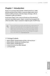
... latest VGA cards and CPU support list on ASRock's website without notice. Chapter 4 contains the configuration guide of the software and utilities. In case any modifications of this manual, Chapter 1 and 2 contains the introduction of this motherboard, please visit our website for specific information about the model you for purchasing ASRock Q1900M / D1800M motherboard, a reliable motherboard produced under ASRock's consistently stringent quality control. In this documentation occur, the updated version will be updated, the...
... latest VGA cards and CPU support list on ASRock's website without notice. Chapter 4 contains the configuration guide of the software and utilities. In case any modifications of this manual, Chapter 1 and 2 contains the introduction of this motherboard, please visit our website for specific information about the model you for purchasing ASRock Q1900M / D1800M motherboard, a reliable motherboard produced under ASRock's consistently stringent quality control. In this documentation occur, the updated version will be updated, the...
User Manual
Page 7
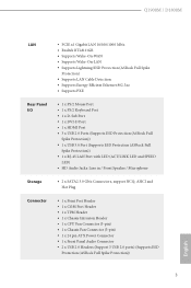
...; 1 x RJ-45 LAN Port with LED (ACT/LINK LED and SPEED LED) • HD Audio Jacks: Line in / Front Speaker / Microphone Storage • 2 x SATA2 3.0 Gb/s Connectors, support NCQ, AHCI and Hot Plug Connector • 1 x Print Port Header • 1 x COM Port Header • 1 x TPM Header • 1 x Chassis Intrusion Header • 1 x CPU Fan Connector (3-pin) • 1 x Chassis Fan Connector (3-pin) • 1 x 24 pin ATX Power Connector • 1 x Front Panel Audio Connector • 2 x USB 2.0 Headers (Support 3 USB 2.0 ports) (Supports ESD Protection (ASRock Full Spike Protection...
...; 1 x RJ-45 LAN Port with LED (ACT/LINK LED and SPEED LED) • HD Audio Jacks: Line in / Front Speaker / Microphone Storage • 2 x SATA2 3.0 Gb/s Connectors, support NCQ, AHCI and Hot Plug Connector • 1 x Print Port Header • 1 x COM Port Header • 1 x TPM Header • 1 x Chassis Intrusion Header • 1 x CPU Fan Connector (3-pin) • 1 x Chassis Fan Connector (3-pin) • 1 x 24 pin ATX Power Connector • 1 x Front Panel Audio Connector • 2 x USB 2.0 Headers (Support 3 USB 2.0 ports) (Supports ESD Protection (ASRock Full Spike Protection...
User Manual
Page 8
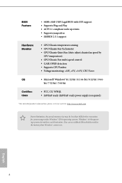
... use . BIOS Feature • 64Mb AMI UEFI Legal BIOS with GUI support • Supports Plug and Play • ACPI 1.1 compliant wake up events • Supports jumperfree • SMBIOS 2.3.1 support Hardware Monitor • CPU/Chassis temperature sensing • CPU/Chassis Fan Tachometer • CPU/Chassis Quiet Fan (Auto adjust chassis fan speed by CPU temperature) • CPU/Chassis Fan multi-speed control • CASE OPEN detection • Supports CPU Fanless • Voltage monitoring: +12V, +5V, +3.3V, CPU Vcore OS • Microsoft® Windows® 8.1 32-bit / 8.1 64-bit...
... use . BIOS Feature • 64Mb AMI UEFI Legal BIOS with GUI support • Supports Plug and Play • ACPI 1.1 compliant wake up events • Supports jumperfree • SMBIOS 2.3.1 support Hardware Monitor • CPU/Chassis temperature sensing • CPU/Chassis Fan Tachometer • CPU/Chassis Quiet Fan (Auto adjust chassis fan speed by CPU temperature) • CPU/Chassis Fan multi-speed control • CASE OPEN detection • Supports CPU Fanless • Voltage monitoring: +12V, +5V, +3.3V, CPU Vcore OS • Microsoft® Windows® 8.1 32-bit / 8.1 64-bit...
User Manual
Page 12
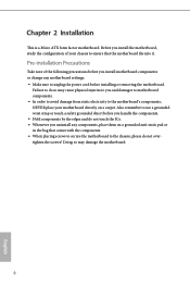
... damage from static electricity to the motherboard's components, NEVER place your chassis to use a grounded wrist strap or touch a safety grounded object before installing or removing the motherboard. Doing so may cause physical injuries to you install motherboard components or change any components, place them on a carpet. Chapter 2 Installation This is a Micro ATX form factor motherboard. Pre-installation Precautions Take note of your...
... damage from static electricity to the motherboard's components, NEVER place your chassis to use a grounded wrist strap or touch a safety grounded object before installing or removing the motherboard. Doing so may cause physical injuries to you install motherboard components or change any components, place them on a carpet. Chapter 2 Installation This is a Micro ATX form factor motherboard. Pre-installation Precautions Take note of your...
User Manual
Page 15
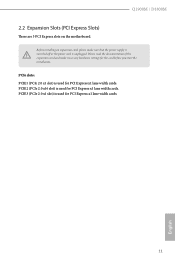
... settings for PCI Express x1 lane width cards. PCIE2 (PCIe 2.0 x16 slot) is unplugged. Please read the documentation of the expansion card and make sure that the power supply is switched off or the power cord is used for PCI Express x1 lane width cards. 11 English Q1900M / D1800M 2.2 Expansion Slots (PCI Express Slots) There are 3 PCI Express slots on the motherboard. PCIe slots: PCIE1 (PCIe 2.0 x1 slot) is used for the card before you start the installation. PCIE3 (PCIe 2.0 x1 slot) is used for PCI Express...
... settings for PCI Express x1 lane width cards. PCIE2 (PCIe 2.0 x16 slot) is unplugged. Please read the documentation of the expansion card and make sure that the power supply is switched off or the power cord is used for PCI Express x1 lane width cards. 11 English Q1900M / D1800M 2.2 Expansion Slots (PCI Express Slots) There are 3 PCI Express slots on the motherboard. PCIe slots: PCIE1 (PCIe 2.0 x1 slot) is used for the card before you start the installation. PCIE3 (PCIe 2.0 x1 slot) is used for PCI Express...
User Manual
Page 16
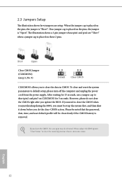
... seconds, use a jumper cap to clear the record of previous chassis intrusion status. Clear CMOS Jumper (CLRCMOS1) (see p.5, No. 9) Default Clear CMOS CLRCMOS1 allows you update the BIOS. Please adjust the BIOS option "Clear Status" to short pin2 and pin3 on these 2 pins. The illustration shows a 3-pin jumper whose pin1 and pin2 are setup. If you do not clear the CMOS right after you to clear the data in CMOS. To clear and reset the system...
... seconds, use a jumper cap to clear the record of previous chassis intrusion status. Clear CMOS Jumper (CLRCMOS1) (see p.5, No. 9) Default Clear CMOS CLRCMOS1 allows you update the BIOS. Please adjust the BIOS option "Clear Status" to short pin2 and pin3 on these 2 pins. The illustration shows a 3-pin jumper whose pin1 and pin2 are setup. If you do not clear the CMOS right after you to clear the data in CMOS. To clear and reset the system...
User Manual
Page 17
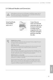
... mainly consists of power switch, reset switch, power LED, hard drive activity LED, speaker and etc. Placing jumper caps over these headers and connectors. System Panel Header (9-pin PANEL1) (see p.5, No. 7) Connect the power switch, reset switch and system status indicator on the chassis front panel. You may differ by chassis. When connecting your system using the power switch. The LED keeps blinking when the system is in S1/S3 sleep state. Note the positive and negative pins before connecting the cables. Press the reset switch...
... mainly consists of power switch, reset switch, power LED, hard drive activity LED, speaker and etc. Placing jumper caps over these headers and connectors. System Panel Header (9-pin PANEL1) (see p.5, No. 7) Connect the power switch, reset switch and system status indicator on the chassis front panel. You may differ by chassis. When connecting your system using the power switch. The LED keeps blinking when the system is in S1/S3 sleep state. Note the positive and negative pins before connecting the cables. Press the reset switch...
User Manual
Page 18
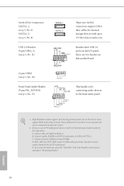
... our manual and chassis manual to 3.0 Gb/s data transfer rate. B. If you use an AC'97 audio panel, please install it to OUT2_L. Connect Mic_IN (MIC) to Ground (GND). Connect Ground (GND) to MIC2_L. D. C. Serial ATA2 Connectors (SATA2_1: see p.5, No. 6) (SATA2_2: see p.5, No. 8) USB 2.0 Headers (9-pin USB4_5) (see p.5, No. 15) 1 GND P- High Definition Audio supports Jack Sensing, but the panel wire on this motherboard. (4-pin USB6) (see p.5, No. 10) Front Panel Audio Header (9-pin HD_AUDIO1...
... our manual and chassis manual to 3.0 Gb/s data transfer rate. B. If you use an AC'97 audio panel, please install it to OUT2_L. Connect Mic_IN (MIC) to Ground (GND). Connect Ground (GND) to MIC2_L. D. C. Serial ATA2 Connectors (SATA2_1: see p.5, No. 6) (SATA2_2: see p.5, No. 8) USB 2.0 Headers (9-pin USB4_5) (see p.5, No. 15) 1 GND P- High Definition Audio supports Jack Sensing, but the panel wire on this motherboard. (4-pin USB6) (see p.5, No. 10) Front Panel Audio Header (9-pin HD_AUDIO1...
User Manual
Page 19
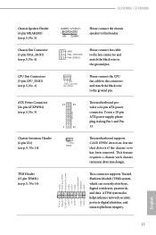
... Please connect the CPU fan cable to the connector and match the black wire to the ground pin. CPU Fan Connectors (3-pin CPU_FAN1) (see p.5, No. 16) 1 13 This motherboard provides a 24-pin ATX power connector. TPM Header (17-pin TPMS1) (see p.5, No. 4) GND FAN_VOLTAGE FAN_SPEED Please connect fan cable to the fan connector and match the black wire to this header. To use a 20-pin ATX power supply, please plug it along Pin 1 and Pin 13. This feature requires a chassis with chassis intrusion detection design. Chassis Fan Connector (3-pin...
... Please connect the CPU fan cable to the connector and match the black wire to the ground pin. CPU Fan Connectors (3-pin CPU_FAN1) (see p.5, No. 16) 1 13 This motherboard provides a 24-pin ATX power connector. TPM Header (17-pin TPMS1) (see p.5, No. 4) GND FAN_VOLTAGE FAN_SPEED Please connect fan cable to the fan connector and match the black wire to this header. To use a 20-pin ATX power supply, please plug it along Pin 1 and Pin 13. This feature requires a chassis with chassis intrusion detection design. Chassis Fan Connector (3-pin...
User Manual
Page 21
... install can work properly. The CD automatically displays the Main Menu if "AUTORUN" is enabled in the Support CD to install those required drivers. Please click Install All or follow the installation wizard to your system will be auto-detected and listed on the file "ASRSETUP.EXE" in your CD-ROM drive. Utilities Menu The Utilities Menu shows the application software that enhance the motherboard's features. If the Main Menu does not appear automatically, locate...
... install can work properly. The CD automatically displays the Main Menu if "AUTORUN" is enabled in the Support CD to install those required drivers. Please click Install All or follow the installation wizard to your system will be auto-detected and listed on the file "ASRSETUP.EXE" in your CD-ROM drive. Utilities Menu The Utilities Menu shows the application software that enhance the motherboard's features. If the Main Menu does not appear automatically, locate...
User Manual
Page 24
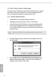
... your motherboard supports this feature. • Operating system: Microsoft Windows 8/7 (32- There are certain risks. Click on the value Start and change the value from Windows® sleep state to AHCI. or 64-bit edition) • Set the SATA mode to refresh email or social networking applications. If Windows 8/7 is not in Windows 8/7, type "Regedit" into the word box then click OK. 2. Press Win + R simultaneously in AHCI mode, please...
... your motherboard supports this feature. • Operating system: Microsoft Windows 8/7 (32- There are certain risks. Click on the value Start and change the value from Windows® sleep state to AHCI. or 64-bit edition) • Set the SATA mode to refresh email or social networking applications. If Windows 8/7 is not in Windows 8/7, type "Regedit" into the word box then click OK. 2. Press Win + R simultaneously in AHCI mode, please...
User Manual
Page 35
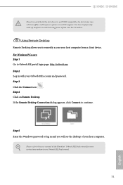
... password. Please refer to the user manual of your host computer. Using Remote Desktop Remote Desktop allows you will dissappear. If the Remote Desktop Connection dialog appears, click Connect to remotely access your host computer from a client device. Step 3 Click the Connect icon . Q1900M / D1800M Please be noted that if the host device is not WOW compatible, the host status icon will turn offline and the power option...
... password. Please refer to the user manual of your host computer. Using Remote Desktop Remote Desktop allows you will dissappear. If the Remote Desktop Connection dialog appears, click Connect to remotely access your host computer from a client device. Step 3 Click the Connect icon . Q1900M / D1800M Please be noted that if the host device is not WOW compatible, the host status icon will turn offline and the power option...
User Manual
Page 42
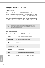
... wish to configure your screen. 4.1.1 UEFI Menu Bar The top of the screen has a menu bar with its test routines. Because the UEFI software is constantly being updated, the following selections: Main For setting system time/date information Advanced For advanced system configurations Tool Useful tools H/W Monitor Displays current hardware status Security For security settings Boot For configuring boot settings and boot priority Exit Exit the current screen or the UEFI Setup Utility English 38...
... wish to configure your screen. 4.1.1 UEFI Menu Bar The top of the screen has a menu bar with its test routines. Because the UEFI software is constantly being updated, the following selections: Main For setting system time/date information Advanced For advanced system configurations Tool Useful tools H/W Monitor Displays current hardware status Security For security settings Boot For configuring boot settings and boot priority Exit Exit the current screen or the UEFI Setup Utility English 38...

User Manual
Page 48
Front Panel Enable/disable front panel HD audio. Primary Graphics Adapter Select a primary VGA. Share Memory Configure the size of memory that is allocated to enable onboard HD audio and automatically disable it when a sound card is [Auto]. Onboard HDMI HD Audio Enable audio for the onboard digital outputs. 44 English Onboard HD Audio Enable/disable onboard HD audio. Set to Auto to the integrated graphics processor when the system boots up. The default value is installed. 4.3.2 Chipset Configuration DRAM Voltage Use this to configure DRAM Voltage.
Front Panel Enable/disable front panel HD audio. Primary Graphics Adapter Select a primary VGA. Share Memory Configure the size of memory that is allocated to enable onboard HD audio and automatically disable it when a sound card is [Auto]. Onboard HDMI HD Audio Enable audio for the onboard digital outputs. 44 English Onboard HD Audio Enable/disable onboard HD audio. Set to Auto to the integrated graphics processor when the system boots up. The default value is installed. 4.3.2 Chipset Configuration DRAM Voltage Use this to configure DRAM Voltage.
User Manual
Page 49
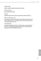
... will start to boot up when the power recovers. If [Power On] is on AC/Power Loss Select the power state after a power failure. Restore on . Good Night LED By enabling Good Night LED, the Power/LAN LEDs will be switched off when the system is selected, the system will also automatically switch off when the power recovers. Deep S5 Configure deep sleep mode for PCIE1. Q1900M / D1800M Onboard LAN Enable or disable the onboard network interface controller.
... will start to boot up when the power recovers. If [Power On] is on AC/Power Loss Select the power state after a power failure. Restore on . Good Night LED By enabling Good Night LED, the Power/LAN LEDs will be switched off when the system is selected, the system will also automatically switch off when the power recovers. Deep S5 Configure deep sleep mode for PCIE1. Q1900M / D1800M Onboard LAN Enable or disable the onboard network interface controller.
User Manual
Page 55
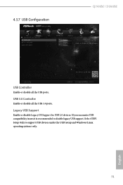
USB 3.0 Controller Enable or disable all the USB ports. Select UEFI Setup Only to disable legacy USB support. 4.3.7 USB Configuration Q1900M / D1800M USB Controller Enable or disable all the USB 3.0 ports. Legacy USB Support Enable or disable Legacy OS Support for USB 2.0 devices. If you encounter USB compatibility issues it is recommended to support USB devices under the UEFI setup and Windows/Linux operating systems only. 51 English
USB 3.0 Controller Enable or disable all the USB ports. Select UEFI Setup Only to disable legacy USB support. 4.3.7 USB Configuration Q1900M / D1800M USB Controller Enable or disable all the USB 3.0 ports. Legacy USB Support Enable or disable Legacy OS Support for USB 2.0 devices. If you encounter USB compatibility issues it is recommended to support USB devices under the UEFI setup and Windows/Linux operating systems only. 51 English
User Manual
Page 57
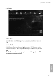
4.4 Tools Q1900M / D1800M Instant Flash Save UEFI files in your USB storage device and run Instant Flash to plug in your UEFI. Please setup network configuration before using Internet Flash. *For BIOS backup and recovery purpose, it is recommended to update your USB pen drive before using this function. 53 English Internet Flash ASRock Internet Flash downloads and updates the latest UEFI firmware version from our servers for you.
4.4 Tools Q1900M / D1800M Instant Flash Save UEFI files in your USB storage device and run Instant Flash to plug in your UEFI. Please setup network configuration before using Internet Flash. *For BIOS backup and recovery purpose, it is recommended to update your USB pen drive before using this function. 53 English Internet Flash ASRock Internet Flash downloads and updates the latest UEFI firmware version from our servers for you.
User Manual
Page 58
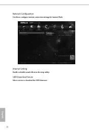
Network Configuration Use this to download the UEFI firmware. 54 English UEFI Download Server Select a server to configure internet connection settings for Internet Flash. Internet Setting Enable or disable sound effects in the setup utility.
Network Configuration Use this to download the UEFI firmware. 54 English UEFI Download Server Select a server to configure internet connection settings for Internet Flash. Internet Setting Enable or disable sound effects in the setup utility.


