Intel Rapid Storage Guide
Page 13
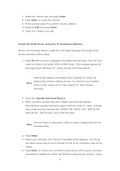
... a floppy disk with a screen asking you have successfully installed the driver and Windows setup should continue. Nothing will temporarily continue loading drivers. Use the Floppy Configuration Utility to create the volume. 9. Press Enter to confirm your exit. Press Y to confirm your controller from the list of Windows XP* setup (during operating system setup: 1. Setup will happen immediately after pressing F6. When you need to confirm volume creation. 10. Install the RAID Driver Using the...
... a floppy disk with a screen asking you have successfully installed the driver and Windows setup should continue. Nothing will temporarily continue loading drivers. Use the Floppy Configuration Utility to create the volume. 9. Press Enter to confirm your exit. Press Y to confirm your controller from the list of Windows XP* setup (during operating system setup: 1. Setup will happen immediately after pressing F6. When you need to confirm volume creation. 10. Install the RAID Driver Using the...
User Manual
Page 9
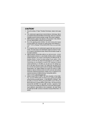
... check page 59. 2. This motherboard supports Dual Channel Memory Technology. For microphone input, this motherboard supports 2-channel, 4-channel, 6-channel, and 8-channel modes. In IES (Intelligent Energy Saver), the voltage regulator can update your system. ASRock website: http://www.asrock.com 7. Just launch this utility, you can save the new BIOS le to your USB ash drive, oppy disk or hard drive, then you can press key during the POST or press key to BIOS setup menu to the operating system...
... check page 59. 2. This motherboard supports Dual Channel Memory Technology. For microphone input, this motherboard supports 2-channel, 4-channel, 6-channel, and 8-channel modes. In IES (Intelligent Energy Saver), the voltage regulator can update your system. ASRock website: http://www.asrock.com 7. Just launch this utility, you can save the new BIOS le to your USB ash drive, oppy disk or hard drive, then you can press key during the POST or press key to BIOS setup menu to the operating system...

User Manual
Page 12
...) 22 Power Switch (PWRBTN) 23 Power LED Header (PLED1) 24 System Panel Header (PANEL1, White) 25 Chassis Speaker Header (SPEAKER 1, White) 26 USB 3.0 Header (USB3_2_3, Light Blue) 27 Dr. Debug 28 USB 2.0 Header (USB12_13, Blue) 29 USB 2.0 Header (USB10_11, Blue) 30 USB 2.0 Header (USB8_9, Blue) 31 Front Panel IEEE 1394 Header (FRONT_1394, White) 32 Infrared Module Header (IR1) 33 Floppy Connector (FLOPPY1) 34 COM Port Header (COM1) 35 Front Panel Audio Header (HD_AUDIO1, White) 36 HDMI_SPDIF Header (HDMI_SPDIF1, White) 37 PCI Express 2.0 x16 Slot...
...) 22 Power Switch (PWRBTN) 23 Power LED Header (PLED1) 24 System Panel Header (PANEL1, White) 25 Chassis Speaker Header (SPEAKER 1, White) 26 USB 3.0 Header (USB3_2_3, Light Blue) 27 Dr. Debug 28 USB 2.0 Header (USB12_13, Blue) 29 USB 2.0 Header (USB10_11, Blue) 30 USB 2.0 Header (USB8_9, Blue) 31 Front Panel IEEE 1394 Header (FRONT_1394, White) 32 Infrared Module Header (IR1) 33 Floppy Connector (FLOPPY1) 34 COM Port Header (COM1) 35 Front Panel Audio Header (HD_AUDIO1, White) 36 HDMI_SPDIF Header (HDMI_SPDIF1, White) 37 PCI Express 2.0 x16 Slot...
User Manual
Page 30
... uninstall any VGA driver installed in your system, there is an optional download. Restart your Windows® taskbar. ATI Catalyst Control Center Step 6. We recommend using this utility to download it again): http://www.microsoft.com/windowsxp/sp2/default.mspx B. For Windows® XP OS: A. Please check AMD website for details. Step 5. Click "View", select "CrossFireXTM", and then check the item "Enable CrossFireXTM". Select...
... uninstall any VGA driver installed in your system, there is an optional download. Restart your Windows® taskbar. ATI Catalyst Control Center Step 6. We recommend using this utility to download it again): http://www.microsoft.com/windowsxp/sp2/default.mspx B. For Windows® XP OS: A. Please check AMD website for details. Step 5. Click "View", select "CrossFireXTM", and then check the item "Enable CrossFireXTM". Select...

User Manual
Page 42
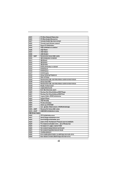
... speci c) South Bridge DXE Initialization (South Bridge module speci c) South Bridge DXE Initialization (South Bridge module speci c) South Bridge DXE Initialization (South Bridge module speci c) ACPI module initialization CSM initialization Reserved for future AMI DXE codes OEM DXE initialization codes Boot Device Selection (BDS) phase is started Driver connecting is started PCI Bus initialization is started PCI Bus Hot Plug Controller Initialization PCI Bus Enumeration 42
... speci c) South Bridge DXE Initialization (South Bridge module speci c) South Bridge DXE Initialization (South Bridge module speci c) South Bridge DXE Initialization (South Bridge module speci c) ACPI module initialization CSM initialization Reserved for future AMI DXE codes OEM DXE initialization codes Boot Device Selection (BDS) phase is started Driver connecting is started PCI Bus initialization is started PCI Bus Hot Plug Controller Initialization PCI Bus Enumeration 42
User Manual
Page 43
... Setup Verifying Password 0xA9 Start of Setup 0xAA Reserved for ASL (see ASL Status Codes section below) 0xAB Setup Input Wait 0xAC Reserved for ASL (see ASL Status Codes section below) 0xAD Ready To Boot event 0xAE Legacy Boot event 0xAF Exit Boot Services event 0xB0 Runtime Set Virtual Address MAP Begin 0xB1 Runtime Set Virtual Address MAP End 0xB2 Legacy Option ROM Initialization 0xB3 System Reset 0xB4 USB hot plug 0xB5 PCI bus...
... Setup Verifying Password 0xA9 Start of Setup 0xAA Reserved for ASL (see ASL Status Codes section below) 0xAB Setup Input Wait 0xAC Reserved for ASL (see ASL Status Codes section below) 0xAD Ready To Boot event 0xAE Legacy Boot event 0xAF Exit Boot Services event 0xB0 Runtime Set Virtual Address MAP Begin 0xB1 Runtime Set Virtual Address MAP End 0xB2 Legacy Option ROM Initialization 0xB3 System Reset 0xB4 USB hot plug 0xB5 PCI bus...

User Manual
Page 49
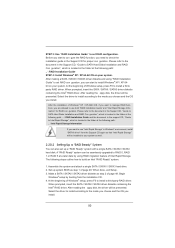
... 64-bit on your system. Start to install those required drivers. B. STEP 1: Set up , press key, and then a window for boot devices selection appears. STEP 2: Make a SATA / SATAII / SATA3 Driver Diskette. A. Then, the drivers compatible to [RAID]. Please follow the order from up to bottom side to format and copy files [YN]? Enter BIOS SETUP UTILITY Advanced screen SATA Con guration. Set the option "SATA Mode" to your optical drive rst. Please select CD-ROM...
... 64-bit on your system. Start to install those required drivers. B. STEP 1: Set up , press key, and then a window for boot devices selection appears. STEP 2: Make a SATA / SATAII / SATA3 Driver Diskette. A. Then, the drivers compatible to [RAID]. Please follow the order from up to bottom side to format and copy files [YN]? Enter BIOS SETUP UTILITY Advanced screen SATA Con guration. Set the option "SATA Mode" to your optical drive rst. Please select CD-ROM...
User Manual
Page 50
... SATA Hard Disks Installation and RAID Con guration", which is located in the folder at the following path: .. \ RAID Installation Guide and the document in the support CD, "Guide to Intel Rapid Storage", which is located in the folder at the following path: .. \ RAID Installation Guide STEP 4: Install Windows® XP / XP 64-bit OS on your system as step 1 of Intel Rapid Storage. When done, exit Setup. 3. Begin Windows® setup by using "RAID Installation Guide...
... SATA Hard Disks Installation and RAID Con guration", which is located in the folder at the following path: .. \ RAID Installation Guide and the document in the support CD, "Guide to Intel Rapid Storage", which is located in the folder at the following path: .. \ RAID Installation Guide STEP 4: Install Windows® XP / XP 64-bit OS on your system as step 1 of Intel Rapid Storage. When done, exit Setup. 3. Begin Windows® setup by using "RAID Installation Guide...
User Manual
Page 51
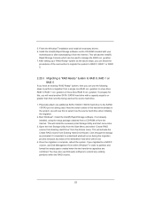
... port not being used . Install the Intel(R) Rapid Storage software via the CD-ROM included with a capacity equal to partition and format the empty space created when the two hard drive capacities are combined. Boot Windows®, install the Intel(R) Rapid Storage software, if not already installed, using the setup package obtained from a CD-ROM or from Existing Hard Drive Wizard. Open the Intel Storage Utility from the Start Menu and select "Create RAID...
... port not being used . Install the Intel(R) Rapid Storage software via the CD-ROM included with a capacity equal to partition and format the empty space created when the two hard drive capacities are combined. Boot Windows®, install the Intel(R) Rapid Storage software, if not already installed, using the setup package obtained from a CD-ROM or from Existing Hard Drive Wizard. Open the Intel Storage Utility from the Start Menu and select "Create RAID...
User Manual
Page 52
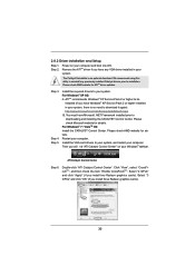
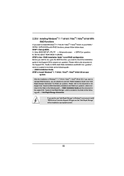
Enter BIOS SETUP UTILITY Advanced screen SATA Con guration. Set the option "SATA Mode" to set RAID configuration. Please refer to the document in the Support CD, "Guide to SATA Hard Disks Installation and RAID Con guration", which is located in the folder at the following path: .. \ RAID Installation Guide STEP 3: Install Windows® 7 / 7 64-bit / VistaTM / VistaTM 64-bit OS on your system. After the installation of Windows® 7 / 7 64-bit / VistaTM / VistaTM 64-bit OS, if you want...
Enter BIOS SETUP UTILITY Advanced screen SATA Con guration. Set the option "SATA Mode" to set RAID configuration. Please refer to the document in the Support CD, "Guide to SATA Hard Disks Installation and RAID Con guration", which is located in the folder at the following path: .. \ RAID Installation Guide STEP 3: Install Windows® 7 / 7 64-bit / VistaTM / VistaTM 64-bit OS on your system. After the installation of Windows® 7 / 7 64-bit / VistaTM / VistaTM 64-bit OS, if you want...

User Manual
Page 69
...use only under legacy OS and UEFI setup when [Disabled] is selected. Legacy USB Support Use this option to select legacy support for legacy USB. [Auto] - Enables support for USB devices. USB devices are allowed to use under UEFI setup and Windows / Linux OS. 69 Enables legacy support if USB devices are four con guration options: [Enabled], [Auto], [Disabled] and [UEFI Setup Only]. There are connected. [Disabled] - Please refer to below descriptions for the details of USB 2.0 controller. 3.3.10 USB Configuration USB 2.0 Controller Use this item to enable or disable the use of USB...
...use only under legacy OS and UEFI setup when [Disabled] is selected. Legacy USB Support Use this option to select legacy support for legacy USB. [Auto] - Enables support for USB devices. USB devices are allowed to use under UEFI setup and Windows / Linux OS. 69 Enables legacy support if USB devices are four con guration options: [Enabled], [Auto], [Disabled] and [UEFI Setup Only]. There are connected. [Disabled] - Please refer to below descriptions for the details of USB 2.0 controller. 3.3.10 USB Configuration USB 2.0 Controller Use this item to enable or disable the use of USB...

User Manual
Page 74
.... Because motherboard settings and hardware options vary, use the setup procedures in your dealer for further information. 74 Refer to visit ASRock's website at http://www.asrock.com; The CD automatically displays the Main Menu if "AUTORUN" is enabled in this chapter for more about ASRock, welcome to your CD-ROM drive. Please install the necessary drivers to display the menus. 4.2.2 Drivers Menu The Drivers Menu shows the available devices drivers if the...
.... Because motherboard settings and hardware options vary, use the setup procedures in your dealer for further information. 74 Refer to visit ASRock's website at http://www.asrock.com; The CD automatically displays the Main Menu if "AUTORUN" is enabled in this chapter for more about ASRock, welcome to your CD-ROM drive. Please install the necessary drivers to display the menus. 4.2.2 Drivers Menu The Drivers Menu shows the available devices drivers if the...

Quick Installation Guide
Page 2
... 1394 Header (FRONT_1394, White) 32 Infrared Module Header (IR1) 33 Floppy Connector (FLOPPY1) 34 COM Port Header (COM1) 35 Front Panel Audio Header (HD_AUDIO1, White) 36 HDMI_SPDIF Header (HDMI_SPDIF1, White) 37 PCI Express 2.0 x16 Slot (PCIE5, Blue) 38 PCI Slot (PCI2) 39 PCI Express 2.0 x16 Slot (PCIE4, Blue) 40 PCI Slot (PCI1) 41 PCI Express 2.0 x1 Slot (PCIE3, White) 42 PCI Express 2.0 x16 Slot (PCIE2, Blue) 43 PCI Express 2.0 x1 Slot (PCIE1, White) 44 SLI / XFIRE Power Connector 45 Chassis Fan Connector (CHA_FAN3) 46 Chassis Fan Connector (CHA_FAN2) 2 ASRock P67 Extreme4 Motherboard...
... 1394 Header (FRONT_1394, White) 32 Infrared Module Header (IR1) 33 Floppy Connector (FLOPPY1) 34 COM Port Header (COM1) 35 Front Panel Audio Header (HD_AUDIO1, White) 36 HDMI_SPDIF Header (HDMI_SPDIF1, White) 37 PCI Express 2.0 x16 Slot (PCIE5, Blue) 38 PCI Slot (PCI2) 39 PCI Express 2.0 x16 Slot (PCIE4, Blue) 40 PCI Slot (PCI1) 41 PCI Express 2.0 x1 Slot (PCIE3, White) 42 PCI Express 2.0 x16 Slot (PCIE2, Blue) 43 PCI Express 2.0 x1 Slot (PCIE1, White) 44 SLI / XFIRE Power Connector 45 Chassis Fan Connector (CHA_FAN3) 46 Chassis Fan Connector (CHA_FAN2) 2 ASRock P67 Extreme4 Motherboard...

Quick Installation Guide
Page 3
... Connector 13 USB 2.0 Ports (USB23) 14 USB 3.0 Ports (USB01) 15 USB 2.0 Ports (USB01) 16 Optical SPDIF Out Port 17 Clear CMOS Switch (CLRCBTN) 18 PS/2 Keyboard Port (Purple) * There are two LED next to the table below for Audio Output Connection Audio Output Channels Front Speaker Rear Speaker Central / Bass Side Speaker (No. 9) (No. 6) (No. 7) (No. 5) 2 V -- -- -- 4 V V -- -- 6 V V V -- 8 V V V V English 3 ASRock P67 Extreme4 Motherboard LAN Port LED Indications Activity/Link LED SPEED LED Status Description Status Description ACT/LINK SPEED LED LED...
... Connector 13 USB 2.0 Ports (USB23) 14 USB 3.0 Ports (USB01) 15 USB 2.0 Ports (USB01) 16 Optical SPDIF Out Port 17 Clear CMOS Switch (CLRCBTN) 18 PS/2 Keyboard Port (Purple) * There are two LED next to the table below for Audio Output Connection Audio Output Channels Front Speaker Rear Speaker Central / Bass Side Speaker (No. 9) (No. 6) (No. 7) (No. 5) 2 V -- -- -- 4 V V -- -- 6 V V V -- 8 V V V V English 3 ASRock P67 Extreme4 Motherboard LAN Port LED Indications Activity/Link LED SPEED LED Status Description Status Description ACT/LINK SPEED LED LED...

Quick Installation Guide
Page 5
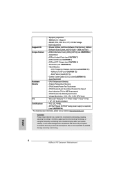
... VGA cards and CPU support lists on ASRock website without notice. ASRock website http://www.asrock.com If you require technical support related to the "User Manual" in Floppy Drive 4 x Serial ATA (SATA) Data Cables (Optional) 2 x Serial ATA (SATA) HDD Power Cables (Optional) 1 x I/O Panel Shield 1 x Front USB 3.0 Panel 4 x HDD Screws 6 x Chassis Screws 1 x Rear USB 3.0 Bracket 1 x ASRock SLI_Bridge_2S Card ASRock Reminds You... www.asrock.com/support/index.asp 1.1 Package Contents ASRock P67 Extreme4 Motherboard (ATX Form Factor: 12.0-in x 9.6-in, 30.5 cm x 24.4 cm) ASRock P67 Extreme4...
... VGA cards and CPU support lists on ASRock website without notice. ASRock website http://www.asrock.com If you require technical support related to the "User Manual" in Floppy Drive 4 x Serial ATA (SATA) Data Cables (Optional) 2 x Serial ATA (SATA) HDD Power Cables (Optional) 1 x I/O Panel Shield 1 x Front USB 3.0 Panel 4 x HDD Screws 6 x Chassis Screws 1 x Rear USB 3.0 Bracket 1 x ASRock SLI_Bridge_2S Card ASRock Reminds You... www.asrock.com/support/index.asp 1.1 Package Contents ASRock P67 Extreme4 Motherboard (ATX Form Factor: 12.0-in x 9.6-in, 30.5 cm x 24.4 cm) ASRock P67 Extreme4...
Quick Installation Guide
Page 8
... setting in the BIOS, applying Untied Overclocking Technology, or using the third-party overclocking tools. ASRock Extreme Tuning Utility (AXTU) (see CAUTION 14) * For detailed product information, please visit our website: http://www.asrock.com WARNING Please realize that there is required) (see CAUTION 6) - CPU/Chassis Fan Multi-Speed Control - DRAM, PCH, CPU PLL, VTT, VCCSA Voltage Multi-adjustment Support CD - Supports jumperfree - CPU/Chassis Quiet Fan (Allow Chassis Fan Speed Auto-Adjust by overclocking. English 8 ASRock P67 Extreme4 Motherboard CPU Frequency...
... setting in the BIOS, applying Untied Overclocking Technology, or using the third-party overclocking tools. ASRock Extreme Tuning Utility (AXTU) (see CAUTION 14) * For detailed product information, please visit our website: http://www.asrock.com WARNING Please realize that there is required) (see CAUTION 6) - CPU/Chassis Fan Multi-Speed Control - DRAM, PCH, CPU PLL, VTT, VCCSA Voltage Multi-adjustment Support CD - Supports jumperfree - CPU/Chassis Quiet Fan (Allow Chassis Fan Speed Auto-Adjust by overclocking. English 8 ASRock P67 Extreme4 Motherboard CPU Frequency...
Quick Installation Guide
Page 9
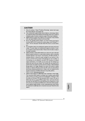
... overclock to read the installation guide of "User Manual" in a few clicks without entering operating systems first like MS-DOS or Windows®. CAUTION! 1. In Hardware Monitor, it shows the fan speed and temperature for proper installation. 3. This motherboard supports Dual Channel Memory Technology. Only K-Series CPU can save the new BIOS file to your friends. For Windows® OS with your USB flash drive, floppy disk or hard drive, then you implement Dual Channel Memory Technology...
... overclock to read the installation guide of "User Manual" in a few clicks without entering operating systems first like MS-DOS or Windows®. CAUTION! 1. In Hardware Monitor, it shows the fan speed and temperature for proper installation. 3. This motherboard supports Dual Channel Memory Technology. Only K-Series CPU can save the new BIOS file to your friends. For Windows® OS with your USB flash drive, floppy disk or hard drive, then you implement Dual Channel Memory Technology...
Quick Installation Guide
Page 26
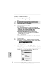
... system. English 26 ASRock P67 Extreme4 Motherboard Power on your system. We recommend using this utility to uninstall any VGA driver installed in your system, there is an optional download. Install the required drivers to download it again): http://www.microsoft.com/windowsxp/sp2/default.mspx B. Double-click "ATI Catalyst Control Center". Step 4. ATITM recommends Windows® XP Service Pack 2 or higher to downloading and installing the CATALYST Control Center. Please check...
... system. English 26 ASRock P67 Extreme4 Motherboard Power on your system. We recommend using this utility to uninstall any VGA driver installed in your system, there is an optional download. Install the required drivers to download it again): http://www.microsoft.com/windowsxp/sp2/default.mspx B. Double-click "ATI Catalyst Control Center". Step 4. ATITM recommends Windows® XP Service Pack 2 or higher to downloading and installing the CATALYST Control Center. Please check...
Quick Installation Guide
Page 39
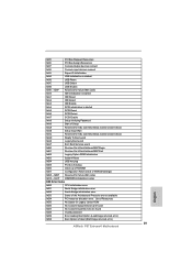
... Setup Verifying Password 0xA9 Start of Setup 0xAA Reserved for ASL (see ASL Status Codes section below) 0xAB Setup Input Wait 0xAC Reserved for ASL (see ASL Status Codes section below) 0xAD Ready To Boot event 0xAE Legacy Boot event 0xAF Exit Boot Services event 0xB0 Runtime Set Virtual Address MAP Begin 0xB1 Runtime Set Virtual Address MAP End 0xB2 Legacy Option ROM Initialization 0xB3 System Reset 0xB4 USB hot plug 0xB5 PCI bus...
... Setup Verifying Password 0xA9 Start of Setup 0xAA Reserved for ASL (see ASL Status Codes section below) 0xAB Setup Input Wait 0xAC Reserved for ASL (see ASL Status Codes section below) 0xAD Ready To Boot event 0xAE Legacy Boot event 0xAF Exit Boot Services event 0xB0 Runtime Set Virtual Address MAP Begin 0xB1 Runtime Set Virtual Address MAP End 0xB2 Legacy Option ROM Initialization 0xB3 System Reset 0xB4 USB hot plug 0xB5 PCI bus...
RAID Installation Guide
Page 7
... 64-bit on your system. Finish the Windows® installation and install all necessary drivers. 7 When prompted, insert the SATA / SATAII driver diskette containing the Intel® RAID driver. When done, exit Setup. 3. Begin Windows® setup by using "RAID Installation Guide" to build an Intel "RAID Ready" system. 1. After reading the floppy disk, the driver will be seamlessly upgraded to RAID 0, RAID 1 or RAID 5 at the following steps outline how to set up system BIOS...
... 64-bit on your system. Finish the Windows® installation and install all necessary drivers. 7 When prompted, insert the SATA / SATAII driver diskette containing the Intel® RAID driver. When done, exit Setup. 3. Begin Windows® setup by using "RAID Installation Guide" to build an Intel "RAID Ready" system. 1. After reading the floppy disk, the driver will be seamlessly upgraded to RAID 0, RAID 1 or RAID 5 at the following steps outline how to set up system BIOS...


