
User Manual
Page 7
... Ready-to-Use USB 3.0 Ports - 1 x RJ-45 LAN Port with LED (ACT/LINK LED and SPEED LED) - 1 x IEEE 1394 Port - 1 x Clear CMOS Switch with GUI support - Front panel audio connector - 3 x USB 2.0 headers (support 6 USB 2.0 ports) - 1 x USB 3.0 header (supports 2 USB 3.0 ports) - 1... x Dr. Debug (7-Segment Debug LED) - 1 x Clear CMOS Switch with LED - 1 x Power Switch with LED - 1 x Reset Switch with eSATA3 port) - 2 x Rear USB 3.0 ports by Etron EJ168A, support USB 1.0/ 2.0/3.0 up to 5Gb...
... Ready-to-Use USB 3.0 Ports - 1 x RJ-45 LAN Port with LED (ACT/LINK LED and SPEED LED) - 1 x IEEE 1394 Port - 1 x Clear CMOS Switch with GUI support - Front panel audio connector - 3 x USB 2.0 headers (support 6 USB 2.0 ports) - 1 x USB 3.0 header (supports 2 USB 3.0 ports) - 1... x Dr. Debug (7-Segment Debug LED) - 1 x Clear CMOS Switch with LED - 1 x Power Switch with LED - 1 x Reset Switch with eSATA3 port) - 2 x Rear USB 3.0 ports by Etron EJ168A, support USB 1.0/ 2.0/3.0 up to 5Gb...

User Manual
Page 12
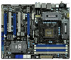
... BASS SATA3 6Gb/s SATA3_0_1 SATA3_M1_M2 CHA_FAN1 CMOS Battery Top: LINE IN Center: Bottom: MIC IN LAN PHY USB 3.0 CHA_FAN3 CHA_FAN2 PCIE1 P67 Extreme4 PCIE2 1394a PCIE3 PCI Express 2.0 Super I/O PCI1 RoHS PCIE4 1 CLRCMOS1 Intel P67 64Mb BIOS SATA2_4_5 SATA2_2_3 AUDIO CODEC HD_AUDIO1...x 240-pin DDR3 DIMM Slots (Dual Channel: DDR3_A2, DDR3_B2, White) 8 ATX Power Connector (ATXPWR1) 9 Chassis Fan Connector (CHA_FAN1) 10 Clear CMOS Jumper (CLRCMOS1) 11 SATA3 Connector (SATA3_M1, White) 12 SATA3 Connector (SATA3_M2, White) 13 SATA3 Connector (SATA3_0, White) 14 SATA3 Connector (...
... BASS SATA3 6Gb/s SATA3_0_1 SATA3_M1_M2 CHA_FAN1 CMOS Battery Top: LINE IN Center: Bottom: MIC IN LAN PHY USB 3.0 CHA_FAN3 CHA_FAN2 PCIE1 P67 Extreme4 PCIE2 1394a PCIE3 PCI Express 2.0 Super I/O PCI1 RoHS PCIE4 1 CLRCMOS1 Intel P67 64Mb BIOS SATA2_4_5 SATA2_2_3 AUDIO CODEC HD_AUDIO1...x 240-pin DDR3 DIMM Slots (Dual Channel: DDR3_A2, DDR3_B2, White) 8 ATX Power Connector (ATXPWR1) 9 Chassis Fan Connector (CHA_FAN1) 10 Clear CMOS Jumper (CLRCMOS1) 11 SATA3 Connector (SATA3_M1, White) 12 SATA3 Connector (SATA3_M2, White) 13 SATA3 Connector (SATA3_0, White) 14 SATA3 Connector (...

User Manual
Page 13
... 1394 Port (IEEE 1394) 12 eSATA3 Connector 13 USB 2.0 Ports (USB23) 14 USB 3.0 Ports (USB01) 15 USB 2.0 Ports (USB01) 16 Optical SPDIF Out Port 17 Clear CMOS Switch (CLRCBTN) 18 PS/2 Keyboard Port (Purple) * There are two LED next to the table below for connection details in accordance with the type of...
... 1394 Port (IEEE 1394) 12 eSATA3 Connector 13 USB 2.0 Ports (USB23) 14 USB 3.0 Ports (USB01) 15 USB 2.0 Ports (USB01) 16 Optical SPDIF Out Port 17 Clear CMOS Switch (CLRCBTN) 18 PS/2 Keyboard Port (Purple) * There are two LED next to the table below for connection details in accordance with the type of...

User Manual
Page 32
... cap to the document at the following path in CMOS. Jumper Clear CMOS Jumper (CLRCMOS1) (see p.12, No. 10) Setting Default Clear CMOS Description Note: CLRCMOS1 allows you can easily enjoy the bene ts of Surround Display feature. However, please do the clear-CMOS action. Please be noted that the password, date,... "Short" when jumper cap is "Short". If you update the BIOS. The Clear CMOS Switch has the same function as the Clear CMOS jumper. 32 To clear and reset the system parameters to clear the CMOS when you just nish updating the BIOS, you must boot up the system rst,...
... cap to the document at the following path in CMOS. Jumper Clear CMOS Jumper (CLRCMOS1) (see p.12, No. 10) Setting Default Clear CMOS Description Note: CLRCMOS1 allows you can easily enjoy the bene ts of Surround Display feature. However, please do the clear-CMOS action. Please be noted that the password, date,... "Short" when jumper cap is "Short". If you update the BIOS. The Clear CMOS Switch has the same function as the Clear CMOS jumper. 32 To clear and reset the system parameters to clear the CMOS when you just nish updating the BIOS, you must boot up the system rst,...

User Manual
Page 39
... two screws into the chassis. 2.12 Smart Switches The motherboard has three smart switches: power switch, reset switch and clear CMOS switch, allowing users to quickly clear the CMOS values. 39 The Installation Guide of Rear USB 3.0 Bracket Step 1 Unscrew the two screws from the Front USB ...Step 2 Put the USB 3.0 cable and the rear USB 3.0 Panel. Clear CMOS Switch (CLRCBTN) (see p.13 No. 17) clr CMOS Clear CMOS Switch is a smart switch, allowing users to quickly turn on /off or reset the sytem clear the CMOS values. Power Switch (PWRBTN) (see p.12 No. 22) RESET ...
... two screws into the chassis. 2.12 Smart Switches The motherboard has three smart switches: power switch, reset switch and clear CMOS switch, allowing users to quickly clear the CMOS values. 39 The Installation Guide of Rear USB 3.0 Bracket Step 1 Unscrew the two screws from the Front USB ...Step 2 Put the USB 3.0 cable and the rear USB 3.0 Panel. Clear CMOS Switch (CLRCBTN) (see p.13 No. 17) clr CMOS Clear CMOS Switch is a smart switch, allowing users to quickly turn on /off or reset the sytem clear the CMOS values. Power Switch (PWRBTN) (see p.12 No. 22) RESET ...

Quick Installation Guide
Page 2
... Slots (Dual Channel: DDR3_A1, DDR3_B1, Blue) 7 2 x 240-pin DDR3 DIMM Slots (Dual Channel: DDR3_A2, DDR3_B2, White) 8 ATX Power Connector (ATXPWR1) 9 Chassis Fan Connector (CHA_FAN1) 10 Clear CMOS Jumper (CLRCMOS1) 11 SATA3 Connector (SATA3_M1, White) 12 SATA3 Connector (SATA3_M2, White) 13 SATA3 Connector (SATA3_0, White) 14 SATA3 Connector (SATA3_1, White) 15 SATA2 Connector... Slot (PCIE2, Blue) 43 PCI Express 2.0 x1 Slot (PCIE1, White) 44 SLI / XFIRE Power Connector 45 Chassis Fan Connector (CHA_FAN3) 46 Chassis Fan Connector (CHA_FAN2) 2 ASRock P67 Extreme4 Motherboard English
... Slots (Dual Channel: DDR3_A1, DDR3_B1, Blue) 7 2 x 240-pin DDR3 DIMM Slots (Dual Channel: DDR3_A2, DDR3_B2, White) 8 ATX Power Connector (ATXPWR1) 9 Chassis Fan Connector (CHA_FAN1) 10 Clear CMOS Jumper (CLRCMOS1) 11 SATA3 Connector (SATA3_M1, White) 12 SATA3 Connector (SATA3_M2, White) 13 SATA3 Connector (SATA3_0, White) 14 SATA3 Connector (SATA3_1, White) 15 SATA2 Connector... Slot (PCIE2, Blue) 43 PCI Express 2.0 x1 Slot (PCIE1, White) 44 SLI / XFIRE Power Connector 45 Chassis Fan Connector (CHA_FAN3) 46 Chassis Fan Connector (CHA_FAN2) 2 ASRock P67 Extreme4 Motherboard English

Quick Installation Guide
Page 3
... (USB01) 16 Optical SPDIF Out Port 17 Clear CMOS Switch (CLRCBTN) 18 PS/2 Keyboard Port (Purple) * There are two LED next to the table below for Audio Output Connection Audio Output Channels Front Speaker Rear Speaker Central / Bass Side Speaker (No. 9) (No. 6) (No. 7) (No. 5) 2 V -- -- -- 4 V V -- -- 6 V V V -- 8 V V V V English 3 ASRock P67 Extreme4 Motherboard Please refer to the LAN port.
... (USB01) 16 Optical SPDIF Out Port 17 Clear CMOS Switch (CLRCBTN) 18 PS/2 Keyboard Port (Purple) * There are two LED next to the table below for Audio Output Connection Audio Output Channels Front Speaker Rear Speaker Central / Bass Side Speaker (No. 9) (No. 6) (No. 7) (No. 5) 2 V -- -- -- 4 V V -- -- 6 V V V -- 8 V V V V English 3 ASRock P67 Extreme4 Motherboard Please refer to the LAN port.
Quick Installation Guide
Page 7
...headers (support 6 USB 2.0 ports) - 1 x USB 3.0 header (supports 2 USB 3.0 ports) - 1 x Dr. Debug (7-Segment Debug LED) - 1 x Clear CMOS Switch with LED - 1 x Power Switch with LED - 1 x Reset Switch with GUI support - SLI/XFire power connector - SATA3 USB3.0 Connector Smart Switch BIOS ...HDMI_SPDIF header - 1 x IEEE 1394 header - 1 x Power LED header - Supports "Plug and Play" - ACPI 1.1 Compliance Wake Up Events 7 ASRock P67 Extreme4 Motherboard English CPU/Chassis/Power FAN connector - 24 pin ATX power connector - 8 pin 12V power connector - HD Audio Jack: Side Speaker/Rear Speaker/...
...headers (support 6 USB 2.0 ports) - 1 x USB 3.0 header (supports 2 USB 3.0 ports) - 1 x Dr. Debug (7-Segment Debug LED) - 1 x Clear CMOS Switch with LED - 1 x Power Switch with LED - 1 x Reset Switch with GUI support - SLI/XFire power connector - SATA3 USB3.0 Connector Smart Switch BIOS ...HDMI_SPDIF header - 1 x IEEE 1394 header - 1 x Power LED header - Supports "Plug and Play" - ACPI 1.1 Compliance Wake Up Events 7 ASRock P67 Extreme4 Motherboard English CPU/Chassis/Power FAN connector - 24 pin ATX power connector - 8 pin 12V power connector - HD Audio Jack: Side Speaker/Rear Speaker/...

Quick Installation Guide
Page 28
... The illustration shows a 3-pin jumper whose pin1 and pin2 are setup. English 28 ASRock P67 Extreme4 Motherboard However, please do the clear-CMOS action. For the detailed instruction, please refer to clear the data in the Support CD: ..\ Surround Display Information 2.8 Jumpers Setup The illustration... shows how jumpers are "Short" when jumper cap is "Short". The Clear CMOS Switch has the same function as the Clear CMOS jumper. After waiting for 5 seconds. Please be noted that the password, date, time, user default pro...
... The illustration shows a 3-pin jumper whose pin1 and pin2 are setup. English 28 ASRock P67 Extreme4 Motherboard However, please do the clear-CMOS action. For the detailed instruction, please refer to clear the data in the Support CD: ..\ Surround Display Information 2.8 Jumpers Setup The illustration... shows how jumpers are "Short" when jumper cap is "Short". The Clear CMOS Switch has the same function as the Clear CMOS jumper. After waiting for 5 seconds. Please be noted that the password, date, time, user default pro...

Quick Installation Guide
Page 35
... into the chassis. 2.10 Smart Switches The motherboard has three smart switches: power switch, reset switch and clear CMOS switch, allowing users to quickly turn on /off or reset the sytem clear the CMOS values. English 35 ASRock P67 Extreme4 Motherboard Clear CMOS Switch (CLRCBTN) (see p.2 No. 22) RESET Reset Switch is a smart switch, allowing users to quickly reset...
... into the chassis. 2.10 Smart Switches The motherboard has three smart switches: power switch, reset switch and clear CMOS switch, allowing users to quickly turn on /off or reset the sytem clear the CMOS values. English 35 ASRock P67 Extreme4 Motherboard Clear CMOS Switch (CLRCBTN) (see p.2 No. 22) RESET Reset Switch is a smart switch, allowing users to quickly reset...
Quick Installation Guide
Page 219
2.8 3 1-2 점퍼 CMOS 초기화 (CLRCMOS1, 3 2 10 세팅 CMOS 삭제 참고 : CLRCMOS1 CMOS 15 CLRCMOS1 의 핀 2 와 핀 3 을 5 BIOS CMOS BIOS CMOS CMOS CMOS 1394 GUID, MAC Clear CMOS Switch는 Clear CMOS 한국어 219 ASRock P67 Extreme4 Motherboard
2.8 3 1-2 점퍼 CMOS 초기화 (CLRCMOS1, 3 2 10 세팅 CMOS 삭제 참고 : CLRCMOS1 CMOS 15 CLRCMOS1 의 핀 2 와 핀 3 을 5 BIOS CMOS BIOS CMOS CMOS CMOS 1394 GUID, MAC Clear CMOS Switch는 Clear CMOS 한국어 219 ASRock P67 Extreme4 Motherboard

Quick Installation Guide
Page 294
2.8 3 1 和針腳 2 CMOS (CLRCMOS1, 3 2 頁第 10 項 ) 設定 默認設置 清除 CMOS 註: C L R C M O S1 C M O S 15 CLRCMOS1 的 pin2 及 pin3 短路 5 BIOS CMOS BIOS CMOS CMOS C M O S 1394 GUID 及 MAC Clear CMOS Clear CMOS 繁體中文 294 ASRock P67 Extreme4 Motherboard
2.8 3 1 和針腳 2 CMOS (CLRCMOS1, 3 2 頁第 10 項 ) 設定 默認設置 清除 CMOS 註: C L R C M O S1 C M O S 15 CLRCMOS1 的 pin2 及 pin3 短路 5 BIOS CMOS BIOS CMOS CMOS C M O S 1394 GUID 及 MAC Clear CMOS Clear CMOS 繁體中文 294 ASRock P67 Extreme4 Motherboard

