
Intel Rapid Storage Guide
Page 12
.... 5. Enetr the Advanced menu. 3. Switch the SATA Operation Mode option to select the drive. Enable RAID in System BIOS Use the instructions included with your motherboard to select the RAID level and press Enter. 4. Use the up or down arrow keys to enable RAID in the system BIOS, a RAID volume must...
.... 5. Enetr the Advanced menu. 3. Switch the SATA Operation Mode option to select the drive. Enable RAID in System BIOS Use the instructions included with your motherboard to select the RAID level and press Enter. 4. Use the up or down arrow keys to enable RAID in the system BIOS, a RAID volume must...

User Manual
Page 2
...purchaser for backup purpose, without notice, and should not be constructed as a commitment by the California Legislature. ASRock assumes no event shall ASRock, its directors, officers, employees, or agents be registered trademarks or copyrights of their respective companies, and are..., USA, please follow the related regulations in Perchlorate Best Management Practices (BMP) regulations passed by ASRock. Products and corporate names appearing in this motherboard contains Perchlorate, a toxic substance controlled in advance. CALIFORNIA, USA ONLY The Lithium battery adopted on...
...purchaser for backup purpose, without notice, and should not be constructed as a commitment by the California Legislature. ASRock assumes no event shall ASRock, its directors, officers, employees, or agents be registered trademarks or copyrights of their respective companies, and are..., USA, please follow the related regulations in Perchlorate Best Management Practices (BMP) regulations passed by ASRock. Products and corporate names appearing in this motherboard contains Perchlorate, a toxic substance controlled in advance. CALIFORNIA, USA ONLY The Lithium battery adopted on...
User Manual
Page 3
Contents 1 Introduction 5 1.1 Package Contents 5 1.2 Specifications 6 1.3 Two SLITM Graphics Card Support List 11 1.4 Two CrossFireXTM Graphics Card Support List 11 1.5 Motherboard Layout 12 1.6 I/O Panel 13 2 Installation 14 2.1 Screw Holes 14 2.2 Pre-installation Precautions 14 2.3 CPU Installation 15 2.4 Installation of Heatsink and CPU fan 17 2.5 Installation of ...
Contents 1 Introduction 5 1.1 Package Contents 5 1.2 Specifications 6 1.3 Two SLITM Graphics Card Support List 11 1.4 Two CrossFireXTM Graphics Card Support List 11 1.5 Motherboard Layout 12 1.6 I/O Panel 13 2 Installation 14 2.1 Screw Holes 14 2.2 Pre-installation Precautions 14 2.3 CPU Installation 15 2.4 Installation of Heatsink and CPU fan 17 2.5 Installation of ...
User Manual
Page 5
... 1: Introduction Thank you are using. www.asrock.com/support/index.asp 1.1 Package Contents ASRock P55 Extreme4 Motherboard (ATX Form Factor: 12.0-in x 9.6-in, 30.5 cm x 24.4 cm) ASRock P55 Extreme4 Quick Installation Guide ASRock P55 Extreme4 Support CD 1 x 80-conductor Ultra ATA 66/100/133 IDE Ribbon Cable 1 x Ribbon Cable for purchasing ASRock P55 Extreme4 motherboard, a reliable motherboard produced under ASRock's consistently stringent quality control. In case...
... 1: Introduction Thank you are using. www.asrock.com/support/index.asp 1.1 Package Contents ASRock P55 Extreme4 Motherboard (ATX Form Factor: 12.0-in x 9.6-in, 30.5 cm x 24.4 cm) ASRock P55 Extreme4 Quick Installation Guide ASRock P55 Extreme4 Support CD 1 x 80-conductor Ultra ATA 66/100/133 IDE Ribbon Cable 1 x Ribbon Cable for purchasing ASRock P55 Extreme4 motherboard, a reliable motherboard produced under ASRock's consistently stringent quality control. In case...
User Manual
Page 9
... Untied Overclocking Technology. For audio output, this motherboard supports both stereo and mono modes. ASRock website: http://www.asrock.com/feature/OCTuner/index.htm 8. Please visit our website for the operation procedures of Intelligent Energy Saver....utility embedded in a few clicks without entering operating systems first like MS-DOS or Windows®. ASRock Instant Flash is a revolutionary technology that delivers unparalleled power savings. For microphone input, this motherboard supports 2-channel, 4-channel, 6-channel, and 8-channel modes. Please check the table on page 18...
... Untied Overclocking Technology. For audio output, this motherboard supports both stereo and mono modes. ASRock website: http://www.asrock.com/feature/OCTuner/index.htm 8. Please visit our website for the operation procedures of Intelligent Energy Saver....utility embedded in a few clicks without entering operating systems first like MS-DOS or Windows®. ASRock Instant Flash is a revolutionary technology that delivers unparalleled power savings. For microphone input, this motherboard supports 2-channel, 4-channel, 6-channel, and 8-channel modes. Please check the table on page 18...

User Manual
Page 10
... 16. All you can start experiencing the exciting motion controlled games. ASRock website: http://www.asrock.com/Feature/Aiwi/index.asp 12. Before you resume the system, please check if the CPU fan on the same motherboard. 11. EuP, stands for Energy Using Product, was a provision regulated...completed system shall be shared and worked on the motherboard functions properly and unplug the power cord, then plug it is just to install the ASRock AIWI utility either from ASRock official website or ASRock software support CD to your motherboard, and also download the free AIWI Lite from your...
... 16. All you can start experiencing the exciting motion controlled games. ASRock website: http://www.asrock.com/Feature/Aiwi/index.asp 12. Before you resume the system, please check if the CPU fan on the same motherboard. 11. EuP, stands for Energy Using Product, was a provision regulated...completed system shall be shared and worked on the motherboard functions properly and unplug the power cord, then plug it is just to install the ASRock AIWI utility either from ASRock official website or ASRock software support CD to your motherboard, and also download the free AIWI Lite from your...
User Manual
Page 12
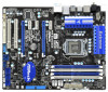
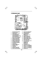
1.5 Motherboard Layout 1 23 4 5 6 7 24.4cm (9.6 in) PS2 Mouse PS2 Keyboard Clr CMOS 1...Top: SIDE SPK Center: REAR SPK FRONT Bottom: CTR BASS MIC IN Top: LINE IN Center: Bottom: 48 PCIE1 P55 Extreme4 LAN PHY 47 PCI Express 2.0 PCIE2 8 CHA_FAN2 SATA3_4 SATA3_3 CHA_FAN3 SATA3_2 SATA3_1 IDE1 9 10 11 12 13 14 15... RoHS Super I/O CMOS Battery ErP/EuP Ready PCIE4 SATA3 6Gb/s NEC USB 3.0 CLRCMOS1 1 Front USB 3.0 PCIE5 Intel P55 RSTBTN AUDIO CODEC 1 IR1 HD_AUDIO1 HDMI_SPDIF1 1 CD1 1 1 COM1 PCI1 PCI2 FLOPPY1 USB3_2_3 PWRBTN USB12_13 SATAII_5 SATAII_6 16Mb BIOS...
1.5 Motherboard Layout 1 23 4 5 6 7 24.4cm (9.6 in) PS2 Mouse PS2 Keyboard Clr CMOS 1...Top: SIDE SPK Center: REAR SPK FRONT Bottom: CTR BASS MIC IN Top: LINE IN Center: Bottom: 48 PCIE1 P55 Extreme4 LAN PHY 47 PCI Express 2.0 PCIE2 8 CHA_FAN2 SATA3_4 SATA3_3 CHA_FAN3 SATA3_2 SATA3_1 IDE1 9 10 11 12 13 14 15... RoHS Super I/O CMOS Battery ErP/EuP Ready PCIE4 SATA3 6Gb/s NEC USB 3.0 CLRCMOS1 1 Front USB 3.0 PCIE5 Intel P55 RSTBTN AUDIO CODEC 1 IR1 HD_AUDIO1 HDMI_SPDIF1 1 CD1 1 1 COM1 PCI1 PCI2 FLOPPY1 USB3_2_3 PWRBTN USB12_13 SATAII_5 SATAII_6 16Mb BIOS...
User Manual
Page 14
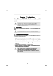
...the power cord is an ATX form factor (12.0" x 9.6", 30.5 x 24.4 cm) motherboard. Hold components by the edges and do so may cause physical injuries to you and damages to motherboard components. 2.1 Screw Holes Place screws into it on the carpet or the like. Also remember... 4. Failure to unplug the power cord before you handle components. 3. Failure to the motherboard, peripherals, and/or components. 14 Chapter 2: Installation This is detached from the wall socket before you install motherboard components or change any component, place it . Doing so may cause severe damage to ...
...the power cord is an ATX form factor (12.0" x 9.6", 30.5 x 24.4 cm) motherboard. Hold components by the edges and do so may cause physical injuries to you and damages to motherboard components. 2.1 Screw Holes Place screws into it on the carpet or the like. Also remember... 4. Failure to unplug the power cord before you handle components. 3. Failure to the motherboard, peripherals, and/or components. 14 Chapter 2: Installation This is detached from the wall socket before you install motherboard components or change any component, place it . Doing so may cause severe damage to ...
User Manual
Page 15
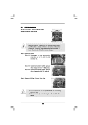
... by depressing down and out on the socket. Rotate the load lever to clear retention tab. Otherwise, the CPU will be placed if returning the motherboard for after service. 15 Open the socket: Step 1-1. Rotate the load plate to handle and avoid kicking off the PnP cap. 2. This cap must be...
... by depressing down and out on the socket. Rotate the load lever to clear retention tab. Otherwise, the CPU will be placed if returning the motherboard for after service. 15 Open the socket: Step 1-1. Rotate the load plate to handle and avoid kicking off the PnP cap. 2. This cap must be...
User Manual
Page 17
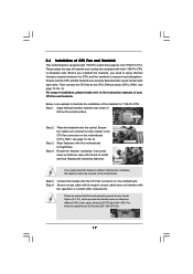
... thumb to install and lock. Ensure fan cables are for 1156-Pin CPU. Step 6. 2.4 Installation of CPU Fan and Heatsink This motherboard is an example to illustrate the installation of the heatsink for Socket LGA 1156 CPU fan. 17 For proper installation, please kindly refer... to the instruction manuals of IHS on the motherboard (CPU_FAN1, see page 12, No. 5). Apply thermal interface material onto center of your CPU fan and heatsink. Apply Thermal Interface Material Step...
... thumb to install and lock. Ensure fan cables are for 1156-Pin CPU. Step 6. 2.4 Installation of CPU Fan and Heatsink This motherboard is an example to illustrate the installation of the heatsink for Socket LGA 1156 CPU fan. 17 For proper installation, please kindly refer... to the instruction manuals of IHS on the motherboard (CPU_FAN1, see page 12, No. 5). Apply thermal interface material onto center of your CPU fan and heatsink. Apply Thermal Interface Material Step...
User Manual
Page 18
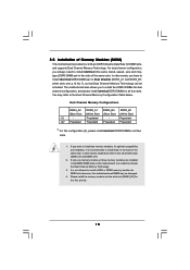
... four slots. Dual Channel Memory Configurations DDR3_A2 DDR3_A1 DDR3_B2 DDR3_B1 (Blue Slot) (White Slot) (Blue Slot) (White Slot) (1) - This motherboard also allows you always need to activate the Dual Channel Memory Technology. 3. Populated - Populated (2)* Populated Populated Populated Populated * For the configuration ...DDR3 DIMMs in the slots of the same color. white slots; Please install the memory module into DDR3 slot;otherwise, this motherboard, it is unable to install identical (the same brand, speed, size and chiptype) DDR3 DIMM pair in Dual Channel (DDR3_A1...
... four slots. Dual Channel Memory Configurations DDR3_A2 DDR3_A1 DDR3_B2 DDR3_B1 (Blue Slot) (White Slot) (Blue Slot) (White Slot) (1) - This motherboard also allows you always need to activate the Dual Channel Memory Technology. 3. Populated - Populated (2)* Populated Populated Populated Populated * For the configuration ...DDR3 DIMMs in the slots of the same color. white slots; Please install the memory module into DDR3 slot;otherwise, this motherboard, it is unable to install identical (the same brand, speed, size and chiptype) DDR3 DIMM pair in Dual Channel (DDR3_A1...
User Manual
Page 19
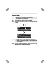
.... Step 2. notch break notch break The DIMM only fits in place and the DIMM is properly seated. 19 Installing a DIMM Please make sure to the motherboard and the DIMM if you force the DIMM into the slot until the retaining clips at incorrect orientation.
.... Step 2. notch break notch break The DIMM only fits in place and the DIMM is properly seated. 19 Installing a DIMM Please make sure to the motherboard and the DIMM if you force the DIMM into the slot until the retaining clips at incorrect orientation.
User Manual
Page 20
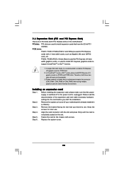
... Installing an expansion card Step 1. Remove the bracket facing the slot that have the 32-bit PCI interface. Fasten the card to motherboard chassis fan connector (CHA_FAN1, CHA_FAN2 or CHA_FAN3) when using multiple graphics cards for later use . Replace the system cover. 20 Please ..., SATA2 card, etc. Step 6. Therefore, both these two slots will work at x8 bandwidth. 3. Remove the system unit cover (if your motherboard is completely seated on PCIE2 slot. 2. Step 3. Blue) is recommended to support CrossFireXTM or SLITM function. 1. Keep the screws for better thermal...
... Installing an expansion card Step 1. Remove the bracket facing the slot that have the 32-bit PCI interface. Fasten the card to motherboard chassis fan connector (CHA_FAN1, CHA_FAN2 or CHA_FAN3) when using multiple graphics cards for later use . Replace the system cover. 20 Please ..., SATA2 card, etc. Step 6. Therefore, both these two slots will work at x8 bandwidth. 3. Remove the system unit cover (if your motherboard is completely seated on PCIE2 slot. 2. Step 3. Blue) is recommended to support CrossFireXTM or SLITM function. 1. Keep the screws for better thermal...
User Manual
Page 21
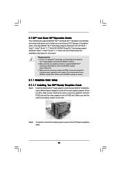
... one graphics card into PCIE2 slot and the other graphics card to the PCI Express graphics cards. 21 2.7 SLITM and Quad SLITM Operation Guide This motherboard supports NVIDIA® SLITM and Quad SLITM (Scalable Link Interface) technology that allows you should have two identical SLITM-ready graphics cards that are properly...
... one graphics card into PCIE2 slot and the other graphics card to the PCI Express graphics cards. 21 2.7 SLITM and Quad SLITM Operation Guide This motherboard supports NVIDIA® SLITM and Quad SLITM (Scalable Link Interface) technology that allows you should have two identical SLITM-ready graphics cards that are properly...
User Manual
Page 25
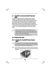
... methods to benefit from the CrossFireXTM multi-GPU platform. 2. Step 1. 2.8 CrossFireXTM and Quad CrossFireXTM Operation Guide This motherboard supports CrossFireXTM and Quad CrossFireXTM feature. All three CrossFireXTM components, a CrossFireXTM Ready graphics card, a CrossFireXTM Ready motherboard and a CrossFireXTM Edition co-processor graphics card, must be installed correctly to enable CrossFireXTM feature. Quad CrossFireXTM...
... methods to benefit from the CrossFireXTM multi-GPU platform. 2. Step 1. 2.8 CrossFireXTM and Quad CrossFireXTM Operation Guide This motherboard supports CrossFireXTM and Quad CrossFireXTM feature. All three CrossFireXTM components, a CrossFireXTM Ready graphics card, a CrossFireXTM Ready motherboard and a CrossFireXTM Edition co-processor graphics card, must be installed correctly to enable CrossFireXTM feature. Quad CrossFireXTM...
User Manual
Page 26
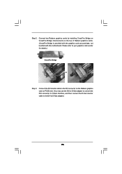
... the Radeon graphics card on the top of Radeon graphics cards. (CrossFire Bridge is provided with the graphics card you purchase, not bundled with this motherboard. Step 2. Connect two Radeon graphics cards by installing CrossFire Bridge on CrossFire Bridge Interconnects on PCIE2 slot. (You may use the DVI to D-Sub adapter...
... the Radeon graphics card on the top of Radeon graphics cards. (CrossFire Bridge is provided with the graphics card you purchase, not bundled with this motherboard. Step 2. Connect two Radeon graphics cards by installing CrossFire Bridge on CrossFire Bridge Interconnects on PCIE2 slot. (You may use the DVI to D-Sub adapter...
User Manual
Page 28
..., please refer to the document at the following path in "ATI Catalyst Control Center" is used only for updates and details. 2.9 Surround Display Feature This motherboard supports Surround Display upgrade. Step 7. Although you can freely enjoy the benefit of CrossFireXTM or Quad CrossFireXTM feature. * CrossFireXTM appearing here is a registered trademark of...
..., please refer to the document at the following path in "ATI Catalyst Control Center" is used only for updates and details. 2.9 Surround Display Feature This motherboard supports Surround Display upgrade. Step 7. Although you can freely enjoy the benefit of CrossFireXTM or Quad CrossFireXTM feature. * CrossFireXTM appearing here is a registered trademark of...
User Manual
Page 30
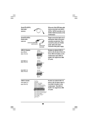
...support SATA data cables for internal storage devices. Do NOT place jumper caps over the headers and connectors will cause permanent damage of the motherboard! 2.11 Onboard Headers and Connectors Onboard headers and connectors are NOT jumpers. Placing jumper caps over these headers and connectors. Serial ATA3 Connectors...data cables for the details. FDD connector (33-pin FLOPPY1) (see p.12 No. 16) PIN1 IDE1 connect the blue end to the motherboard connect the black end to the IDE devices 80-conductor ATA 66/100/133 cable Note: Please refer to 6.0 Gb/s data transfer rate. ...
...support SATA data cables for internal storage devices. Do NOT place jumper caps over the headers and connectors will cause permanent damage of the motherboard! 2.11 Onboard Headers and Connectors Onboard headers and connectors are NOT jumpers. Placing jumper caps over these headers and connectors. Serial ATA3 Connectors...data cables for the details. FDD connector (33-pin FLOPPY1) (see p.12 No. 16) PIN1 IDE1 connect the blue end to the motherboard connect the black end to the IDE devices 80-conductor ATA 66/100/133 cable Note: Please refer to 6.0 Gb/s data transfer rate. ...
User Manual
Page 31
Besides six default USB 2.0 ports on the I /O panel, there is one USB 3.0 header on this motherboard. Then connect the white end of SATA power cable to the power connector of SATA power cable to the power ...+ IntA_P2_SSTXGND IntA_P2_SSRX+ IntA_P2_SSRXVbus 1 Vbus IntA_P1_SSRXIntA_P1_SSRX+ GND IntA_P1_SSTXIntA_P1_SSTX+ GND IntA_P1_DIntA_P1_D+ ID Besides two default USB 3.0 ports on the I /O panel, there are three USB 2.0 headers on this motherboard. This USB 3.0 header can support two USB 2.0 ports. USB 3.0 Header (19-pin USB3_2_3) (see p.12 No. 35) USB_PWR P-9 P+9 GND DUMMY 1 GND P+8 P-8...
Besides six default USB 2.0 ports on the I /O panel, there is one USB 3.0 header on this motherboard. Then connect the white end of SATA power cable to the power connector of SATA power cable to the power ...+ IntA_P2_SSTXGND IntA_P2_SSRX+ IntA_P2_SSRXVbus 1 Vbus IntA_P1_SSRXIntA_P1_SSRX+ GND IntA_P1_SSTXIntA_P1_SSTX+ GND IntA_P1_DIntA_P1_D+ ID Besides two default USB 3.0 ports on the I /O panel, there are three USB 2.0 headers on this motherboard. This USB 3.0 header can support two USB 2.0 ports. USB 3.0 Header (19-pin USB3_2_3) (see p.12 No. 35) USB_PWR P-9 P+9 GND DUMMY 1 GND P+8 P-8...
User Manual
Page 34
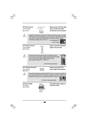
...12V Power Connector 8 5 (8-pin ATX12V1) (see p.12 No. 1) 4 1 Please connect an ATX 12V power supply to the ground pin. 1 2 3 4 Though this motherboard provides 4-Pin CPU fan (Quiet Fan) support, the 3-Pin CPU fan still can still work if you adopt a traditional 4-pin ATX 12V power supply. Though... this motherboard provides 8-pin ATX 12V power connector, it can work if you adopt a traditional 20-pin ATX power supply. CPU Fan Connector (4-pin CPU_FAN1) ...
...12V Power Connector 8 5 (8-pin ATX12V1) (see p.12 No. 1) 4 1 Please connect an ATX 12V power supply to the ground pin. 1 2 3 4 Though this motherboard provides 4-Pin CPU fan (Quiet Fan) support, the 3-Pin CPU fan still can still work if you adopt a traditional 4-pin ATX 12V power supply. Though... this motherboard provides 8-pin ATX 12V power connector, it can work if you adopt a traditional 20-pin ATX power supply. CPU Fan Connector (4-pin CPU_FAN1) ...

