
User Manual
Page 3
...2.9 Making An SATA Driver Diskette 20 3. Introduction 5 1.1 Package Contents 5 1.2 Specifications 6 1.3 Motherboard Layout 8 1.4 ASRock I/O Plus 9 TM 2. BIOS SETUP UTILITY 21 3.1 Introduction 21 3.1.1 BIOS Menu Bar 21 3.1.2 Navigation Keys 22 3.2 Main Screen 22 3.3 Advanced Screen... 23 3.3.1 CPU Configuration 23 3.3.2 Chipset Configuration 24 3.3.3 ACPI Configuration 26 3.3.4 IDE Configuration 27 3.3.5 PCIPnP Configuration 29 3.3.6 Floppy Configuration 29 ...
...2.9 Making An SATA Driver Diskette 20 3. Introduction 5 1.1 Package Contents 5 1.2 Specifications 6 1.3 Motherboard Layout 8 1.4 ASRock I/O Plus 9 TM 2. BIOS SETUP UTILITY 21 3.1 Introduction 21 3.1.1 BIOS Menu Bar 21 3.1.2 Navigation Keys 22 3.2 Main Screen 22 3.3 Advanced Screen... 23 3.3.1 CPU Configuration 23 3.3.2 Chipset Configuration 24 3.3.3 ACPI Configuration 26 3.3.4 IDE Configuration 27 3.3.5 PCIPnP Configuration 29 3.3.6 Floppy Configuration 29 ...
User Manual
Page 5
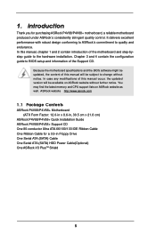
....asrock.com 1.1 Package Contents ASRock P4V88/P4V88+ Motherboard (ATX Form Factor: 12.0-in x 8.6-in Floppy Drive One Serial ATA (SATA) Cable One Serial ATA (SATA) HDD Power Cable(Optional) One ASRock I/O PlusTM Shield 5 It delivers excellent performance with robust design conforming to ASRock's commitment to change without further notice. You may find the latest memory and CPU...
....asrock.com 1.1 Package Contents ASRock P4V88/P4V88+ Motherboard (ATX Form Factor: 12.0-in x 8.6-in Floppy Drive One Serial ATA (SATA) Cable One Serial ATA (SATA) HDD Power Cable(Optional) One ASRock I/O PlusTM Shield 5 It delivers excellent performance with robust design conforming to ASRock's commitment to change without further notice. You may find the latest memory and CPU...
User Manual
Page 6
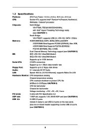
1.2 Specifications Platform: CPU: ATX Form Factor: 12.0-in x 8.6-in, 30.5 cm x 21.8 cm Socket 478, supports Intel® Pentium® 4 (Prescott, Northwood, Willimate) / Celeron® processor Chipsets: North... drives Audio: 5.1 channels AC'97 Audio LAN: Speed: 802.3u (10/100 Ethernet), supports Wake-On-LAN Hardware Monitor: CPU temperature sensing Chassis temperature sensing CPU overheat shutdown to protect CPU life (ASRock U-COP)(see CAUTION 3) CPU fan tachometer Chassis fan tachometer Voltage monitoring: +12V, +5V, +3V, Vcore PCI slots: 5 slots with PCI Specification 2.2 ...
1.2 Specifications Platform: CPU: ATX Form Factor: 12.0-in x 8.6-in, 30.5 cm x 21.8 cm Socket 478, supports Intel® Pentium® 4 (Prescott, Northwood, Willimate) / Celeron® processor Chipsets: North... drives Audio: 5.1 channels AC'97 Audio LAN: Speed: 802.3u (10/100 Ethernet), supports Wake-On-LAN Hardware Monitor: CPU temperature sensing Chassis temperature sensing CPU overheat shutdown to protect CPU life (ASRock U-COP)(see CAUTION 3) CPU fan tachometer Chassis fan tachometer Voltage monitoring: +12V, +5V, +3V, Vcore PCI slots: 5 slots with PCI Specification 2.2 ...
User Manual
Page 7
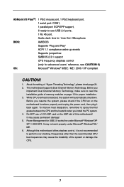
... / Line Out / Microphone BIOS: AMI BIOS Supports "Plug and Play" ACPI 1.1 compliance wake up events Supports jumperfree SMBIOS 2.3.1 support CPU frequency stepless control (only for proper installation. 3. ASRock I/O PlusTM: 1 PS/2 mouse port, 1 PS/2 keyboard port, 1 serial port: COM1, 1 parallel port: ECP/EPP support,...Although this motherboard! To improve heat dissipation, remember to spray thermal grease between the CPU and the heatsink when you resume the system, please check if the CPU fan on the motherboard functions properly and unplug the power cord, then plug it is...
... / Line Out / Microphone BIOS: AMI BIOS Supports "Plug and Play" ACPI 1.1 compliance wake up events Supports jumperfree SMBIOS 2.3.1 support CPU frequency stepless control (only for proper installation. 3. ASRock I/O PlusTM: 1 PS/2 mouse port, 1 PS/2 keyboard port, 1 serial port: COM1, 1 parallel port: ECP/EPP support,...Although this motherboard! To improve heat dissipation, remember to spray thermal grease between the CPU and the heatsink when you resume the system, please check if the CPU fan on the motherboard functions properly and unplug the power cord, then plug it is...
User Manual
Page 8
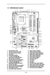
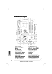
... Audio CODEC LAN PHY VPIACT8h8ip0seAtGP 8X 1.5V_AGP1 PCI 1 IDE1 SATA2 Super I/O 2MB BIOS GAME1 PCI 2 USB2.0 FSB800 DDR400 PCI 3 5.1 CH PCI 4 ATA133 SATA PCI 5 1 IR1 P4V88+ VIA VT8237 CMOS Battery CLRCMOS1 FLOPPY1 SATA1 USB67 1 CHA_FAN1 SPEAKER1 1 PANEL 1 PLED PWRBTN 1 HDLED RESET 9 10 11 12 13 14 15 16 22 21 20...
... Audio CODEC LAN PHY VPIACT8h8ip0seAtGP 8X 1.5V_AGP1 PCI 1 IDE1 SATA2 Super I/O 2MB BIOS GAME1 PCI 2 USB2.0 FSB800 DDR400 PCI 3 5.1 CH PCI 4 ATA133 SATA PCI 5 1 IR1 P4V88+ VIA VT8237 CMOS Battery CLRCMOS1 FLOPPY1 SATA1 USB67 1 CHA_FAN1 SPEAKER1 1 PANEL 1 PLED PWRBTN 1 HDLED RESET 9 10 11 12 13 14 15 16 22 21 20...
User Manual
Page 11
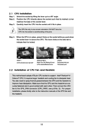
...up to the CPU_FAN connector (CPU_FAN1, see p.8 No. 2). Step 4. Then connect the CPU fan to a 90° angle. Carefully insert the CPU into the socket to avoid bending of the pins. The CPU fits only in place. It requires larger heatsink and cooling fan to improve heat dissipation...., please kindly refer to support Intel® Pentium® 4 / Celeron® CPU. 2.1 CPU Installation Step 1. Step 3. DO NOT force the CPU into the socket until it firmly on the side tab to secure the CPU. The lever clicks on the socket while you push down the socket lever to indicate...
...up to the CPU_FAN connector (CPU_FAN1, see p.8 No. 2). Step 4. Then connect the CPU fan to a 90° angle. Carefully insert the CPU into the socket to avoid bending of the pins. The CPU fits only in place. It requires larger heatsink and cooling fan to improve heat dissipation...., please kindly refer to support Intel® Pentium® 4 / Celeron® CPU. 2.1 CPU Installation Step 1. Step 3. DO NOT force the CPU into the socket until it firmly on the side tab to secure the CPU. The lever clicks on the socket while you push down the socket lever to indicate...
User Manual
Page 18
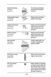
... ATX power supply to this header. Failing to do so will cause the failure to the ground pin. CPU_FAN_SPEED +12V GND Please connect the CPU fan cable to this connector and match the black wire to the ground pin. +5V JBB1 JBX MIDI_OUT JBY JBB2 MIDI_IN Connect a Game cable... the Game port bracket is necessary to connect a power supply with ATX 12V plug to this connector. Chassis Fan Connector (3-pin CHA_FAN1) (see p.8, No. 19) CPU Fan Connector (3-pin CPU_FAN1) (see p.8, No. 2) Game Connector (15-pin GAME1) (see p.8, No. 22) ATX Power Connector (20-pin ATXPWR1) (see p.8, No. 18) ...
... ATX power supply to this header. Failing to do so will cause the failure to the ground pin. CPU_FAN_SPEED +12V GND Please connect the CPU fan cable to this connector and match the black wire to the ground pin. +5V JBB1 JBX MIDI_OUT JBY JBB2 MIDI_IN Connect a Game cable... the Game port bracket is necessary to connect a power supply with ATX 12V plug to this connector. Chassis Fan Connector (3-pin CHA_FAN1) (see p.8, No. 19) CPU Fan Connector (3-pin CPU_FAN1) (see p.8, No. 2) Game Connector (15-pin GAME1) (see p.8, No. 22) ATX Power Connector (20-pin ATXPWR1) (see p.8, No. 18) ...
User Manual
Page 22
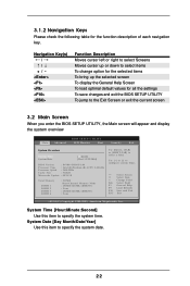
... UTILITY Main Advanced H/W Monitor Boot Security Exit System Overview System Time System Date [17:00:09] [Wed 12/22/2004] BIOS Version : P4V88+ BIOS P1.00 Processor Type : Intel (R) Pentium (R) 4 CPU 2.40 GHz Processor Speed : 2400 MHz Cache Size : 512KB Microcode Update : 0F24/1E Total Memory DIMM 1 DIMM 2 DIMM 3 DIMM 4 : 512MB Dual...
... UTILITY Main Advanced H/W Monitor Boot Security Exit System Overview System Time System Date [17:00:09] [Wed 12/22/2004] BIOS Version : P4V88+ BIOS P1.00 Processor Type : Intel (R) Pentium (R) 4 CPU 2.40 GHz Processor Speed : 2400 MHz Cache Size : 512KB Microcode Update : 0F24/1E Total Memory DIMM 1 DIMM 2 DIMM 3 DIMM 4 : 512MB Dual...
User Manual
Page 23
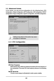
...(C) Copyright 1985-2003, American Megatrends, Inc. 3.3 Advanced Screen In this motherboard. The actual CPU host frequency will show in the following items: CPU Configuration, Chipset Configuration, ACPI Configuration, IDE Configuration, PCIPnP Configuration, Floppy Configuration, SuperIO Configuration,... values in below sections may cause the system to malfunction. 3.3.1 CPU Configuration BIOS SETUP UTILITY Advanced CPU Configuration CPU Host Frequency Actual Frequency (MHz) Spread Spectrum Ratio Status Ratio Actual Value CPU Thermal Throttling [Auto] [133] [Disabled] : Locked : 18...
...(C) Copyright 1985-2003, American Megatrends, Inc. 3.3 Advanced Screen In this motherboard. The actual CPU host frequency will show in the following items: CPU Configuration, Chipset Configuration, ACPI Configuration, IDE Configuration, PCIPnP Configuration, Floppy Configuration, SuperIO Configuration,... values in below sections may cause the system to malfunction. 3.3.1 CPU Configuration BIOS SETUP UTILITY Advanced CPU Configuration CPU Host Frequency Actual Frequency (MHz) Spread Spectrum Ratio Status Ratio Actual Value CPU Thermal Throttling [Auto] [133] [Disabled] : Locked : 18...
User Manual
Page 24
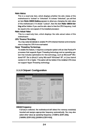
...of this motherboard. DRAM Frequency If [Auto] is selected, the motherboard will be hidden. Set to keep the CPU from overheated. You may select [Enabled] to enable P4 CPU internal thermal control mechanism to [Auto] if using Microsoft® Windows® XP, or Linux kernel version ...Unlocked", you will be equal to allow you use the ratio value to time the CPU frequency, it shows "Locked", then the item Ratio CMOS Setting will be hidden if the installed CPU does not support Hyper-Threading technology. 3.3.2 Chipset Configuration BIOS SETUP UTILITY Advanced Chipset Configuration...
...of this motherboard. DRAM Frequency If [Auto] is selected, the motherboard will be hidden. Set to keep the CPU from overheated. You may select [Enabled] to enable P4 CPU internal thermal control mechanism to [Auto] if using Microsoft® Windows® XP, or Linux kernel version ...Unlocked", you will be equal to allow you use the ratio value to time the CPU frequency, it shows "Locked", then the item Ratio CMOS Setting will be hidden if the installed CPU does not support Hyper-Threading technology. 3.3.2 Chipset Configuration BIOS SETUP UTILITY Advanced Chipset Configuration...
User Manual
Page 25
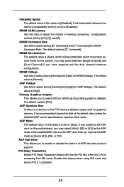
... select the proper access mode for DRAM Command Rate. DRAM Bus Selection The default value is [Auto], which will free the PCI Bus when the CPU is a 4X-AGP card, then you have properly set the AGP mode as the primary graphics adapter. It is set to [Enabled]. The default vaule...
... select the proper access mode for DRAM Command Rate. DRAM Bus Selection The default value is [Auto], which will free the PCI Bus when the CPU is a 4X-AGP card, then you have properly set the AGP mode as the primary graphics adapter. It is set to [Enabled]. The default vaule...
User Manual
Page 32
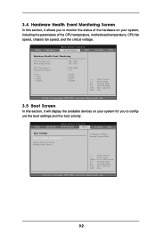
... Configuration Boot Device Priority Removable Drives Configure Settings during System Boot. Main Advanced BIOS SETUP UTILITY H/W Monitor Boot Security Exit Hardware Health Event Monitoring CPU Temperature M / B Temperature CPU Fan Speed Chassis Fan Speed Vcore + 3.30V + 5.00V + 12.00V : 37 C / 98 F : 31 C / 87 F : 2463 RPM : N/A : 1.... system for you to monitor the status of the hardware on your system, including the parameters of the CPU temperature, motherboard temperature, CPU fan speed, chassis fan speed, and the critical voltage. Select Screen Select Item Enter Go to Sub ...
... Configuration Boot Device Priority Removable Drives Configure Settings during System Boot. Main Advanced BIOS SETUP UTILITY H/W Monitor Boot Security Exit Hardware Health Event Monitoring CPU Temperature M / B Temperature CPU Fan Speed Chassis Fan Speed Vcore + 3.30V + 5.00V + 12.00V : 37 C / 98 F : 31 C / 87 F : 2463 RPM : N/A : 1.... system for you to monitor the status of the hardware on your system, including the parameters of the CPU temperature, motherboard temperature, CPU fan speed, chassis fan speed, and the critical voltage. Select Screen Select Item Enter Go to Sub ...
Quick Installation Guide
Page 2
... Header (AUDIO1) 28 Internal Audio Connector: AUX1 (White) 29 Internal Audio Connector: CD1 (Black) 30 Shared USB 2.0 Header (USB4_5, Blue) 31 ATX Power Connector (ATXPWR1) 2 ASRock P4V88/P4V88+ Motherboard Blue) 7 ATX 12V Connector (ATX12V1) 8 Secondary IDE Connector (IDE2, Black) 9 Primary IDE Connector (IDE1, Blue) 10 2 x 184-pin DDR DIMM Slots (Dual Channel B: DDR2...
... Header (AUDIO1) 28 Internal Audio Connector: AUX1 (White) 29 Internal Audio Connector: CD1 (Black) 30 Shared USB 2.0 Header (USB4_5, Blue) 31 ATX Power Connector (ATXPWR1) 2 ASRock P4V88/P4V88+ Motherboard Blue) 7 ATX 12V Connector (ATX12V1) 8 Secondary IDE Connector (IDE2, Black) 9 Primary IDE Connector (IDE1, Blue) 10 2 x 184-pin DDR DIMM Slots (Dual Channel B: DDR2...
Quick Installation Guide
Page 4
...CPU support lists on ASRock website without notice. This Quick Installation Guide contains introduction of the motherboard can be found in the user manual presented in Floppy Drive One Serial ATA (SATA) Cable One Serial ATA (SATA) HDD Power Cable(Optional) One ASRock I/O PlusTM Shield 4 ASRock P4V88/P4V88... be subject to quality and endurance. ASRock website http://www.asrock.com 1.1 Package Contents ASRock P4V88/P4V88+ Motherboard (ATX Form Factor: 12.0-in x 8.6-in, 30.5 cm x 21.8 cm) ASRock P4V88/P4V88+ Quick Installation Guide ASRock P4V88/P4V88+ Support CD One 80-conductor Ultra ATA...
...CPU support lists on ASRock website without notice. This Quick Installation Guide contains introduction of the motherboard can be found in the user manual presented in Floppy Drive One Serial ATA (SATA) Cable One Serial ATA (SATA) HDD Power Cable(Optional) One ASRock I/O PlusTM Shield 4 ASRock P4V88/P4V88... be subject to quality and endurance. ASRock website http://www.asrock.com 1.1 Package Contents ASRock P4V88/P4V88+ Motherboard (ATX Form Factor: 12.0-in x 8.6-in, 30.5 cm x 21.8 cm) ASRock P4V88/P4V88+ Quick Installation Guide ASRock P4V88/P4V88+ Support CD One 80-conductor Ultra ATA...
Quick Installation Guide
Page 5
... drives Audio: 5.1 channels AC'97 Audio LAN: Speed: 802.3u (10/100 Ethernet), supports Wake-On-LAN Hardware Monitor: CPU temperature sensing, Chassis temperature sensing, CPU overheat shutdown to protect CPU life (ASRock U-COP)(see CAUTION 3), CPU fan tachometer, Chassis fan tachometer, Voltage monitoring: +12V, +5V, +3V, Vcore PCI slots: 5 slots with PCI Specification 2.2 AGP...4) USB 2.0: 8 USB 2.0 ports: include 6 ready-to-use USB 2.0 ports on the rear panel, plus one on-board header supporting 2 extra USB 2.0 ports (see CAUTION 5) English 5 ASRock P4V88/P4V88+ Motherboard
... drives Audio: 5.1 channels AC'97 Audio LAN: Speed: 802.3u (10/100 Ethernet), supports Wake-On-LAN Hardware Monitor: CPU temperature sensing, Chassis temperature sensing, CPU overheat shutdown to protect CPU life (ASRock U-COP)(see CAUTION 3), CPU fan tachometer, Chassis fan tachometer, Voltage monitoring: +12V, +5V, +3V, Vcore PCI slots: 5 slots with PCI Specification 2.2 AGP...4) USB 2.0: 8 USB 2.0 ports: include 6 ready-to-use USB 2.0 ports on the rear panel, plus one on-board header supporting 2 extra USB 2.0 ports (see CAUTION 5) English 5 ASRock P4V88/P4V88+ Motherboard
Quick Installation Guide
Page 6
Before you resume the system, please check if the CPU fan on page 8 for USB 2.0 works fine under Microsoft® Windows® 98/ ME. 6. It may not work properly under Microsoft® Windows® XP SP1/2000 SP4. English 6 ASRock P4V88/P4V88+ Motherboard Power Management for proper installation. 3. Before you install the PC system. 4. Do...
Before you resume the system, please check if the CPU fan on page 8 for USB 2.0 works fine under Microsoft® Windows® 98/ ME. 6. It may not work properly under Microsoft® Windows® XP SP1/2000 SP4. English 6 ASRock P4V88/P4V88+ Motherboard Power Management for proper installation. 3. Before you install the PC system. 4. Do...
Quick Installation Guide
Page 7
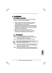
...antstatic pad or in place, press it is locked. STEP 3: Carefully insert the CPU into the socket to static electricity, NEVER place your CPU fan and heatsink vendors. 7 ASRock P4V88/P4V88+ Motherboard English DO NOT force the CPU into the socket until it on the carpet or the like. The lever clicks... down the socket lever to the motherboard, peripherals, and/or components. 2. Failure to do not touch the ICs. 4. The CPU fits only in place. Installation Pre-installation Precautions Take note of the socket lever. Whenever you handle components. 3. STEP 2: Position the...
...antstatic pad or in place, press it is locked. STEP 3: Carefully insert the CPU into the socket to static electricity, NEVER place your CPU fan and heatsink vendors. 7 ASRock P4V88/P4V88+ Motherboard English DO NOT force the CPU into the socket until it on the carpet or the like. The lever clicks... down the socket lever to the motherboard, peripherals, and/or components. 2. Failure to do not touch the ICs. 4. The CPU fits only in place. Installation Pre-installation Precautions Take note of the socket lever. Whenever you handle components. 3. STEP 2: Position the...
Quick Installation Guide
Page 14
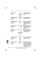
... wire to the ground pin. Please connect the chassis speaker to this connector. Failing to do so will cause the failure to power up. 14 ASRock P4V88/P4V88+ Motherboard System Panel Header (9-pin PANEL1) (see p.2 No. 17) Chassis Speaker Header (4-pin SPEAKER 1) (see p.2 No. 18) Chassis Fan Connector ...(3-pin CHA_FAN1) (see p.2 No. 19) CPU Fan Connector (3-pin CPU_FAN1) (see p.2 No. 2) Game Connector (15-pin GAME1) (see p.2 No. 31) Please connect an ATX power supply to this header....
... wire to the ground pin. Please connect the chassis speaker to this connector. Failing to do so will cause the failure to power up. 14 ASRock P4V88/P4V88+ Motherboard System Panel Header (9-pin PANEL1) (see p.2 No. 17) Chassis Speaker Header (4-pin SPEAKER 1) (see p.2 No. 18) Chassis Fan Connector ...(3-pin CHA_FAN1) (see p.2 No. 19) CPU Fan Connector (3-pin CPU_FAN1) (see p.2 No. 2) Game Connector (15-pin GAME1) (see p.2 No. 31) Please connect an ATX power supply to this header....
User Manual
Page 3
... 5 1.1 Package Contents 5 1.2 Specifications 6 1.3 Motherboard Layout 8 1.4 ASRock I/O Plus 9 TM 2. Installation 10 Pre-installation Precautions 10 2.1 CPU Installation 11 2.2 Installation of CPU Fan and Heatsink 11 2.3 Installation of Memory Modules (DIMM 12 2.4 Expansion...UTILITY 21 3.1 Introduction 21 3.1.1 BIOS Menu Bar 21 3.1.2 Navigation Keys 22 3.2 Main Screen 22 3.3 Advanced Screen 23 3.3.1 CPU Configuration 23 3.3.2 Chipset Configuration 24 3.3.3 ACPI Configuration 26 3.3.4 IDE Configuration 27 3.3.5 PCIPnP Configuration 29 3.3.6 Floppy Configuration 29 3.3.7...
... 5 1.1 Package Contents 5 1.2 Specifications 6 1.3 Motherboard Layout 8 1.4 ASRock I/O Plus 9 TM 2. Installation 10 Pre-installation Precautions 10 2.1 CPU Installation 11 2.2 Installation of CPU Fan and Heatsink 11 2.3 Installation of Memory Modules (DIMM 12 2.4 Expansion...UTILITY 21 3.1 Introduction 21 3.1.1 BIOS Menu Bar 21 3.1.2 Navigation Keys 22 3.2 Main Screen 22 3.3 Advanced Screen 23 3.3.1 CPU Configuration 23 3.3.2 Chipset Configuration 24 3.3.3 ACPI Configuration 26 3.3.4 IDE Configuration 27 3.3.5 PCIPnP Configuration 29 3.3.6 Floppy Configuration 29 3.3.7...
User Manual
Page 5
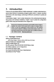
You may find the latest memory and CPU support lists on ASRock website without notice. In this manual occur, the updated version will be available on ASRock website as well. ASRock website http://www.asrock.com 1.1 Package Contents ASRock P4V88 Motherboard (ATX Form Factor: 12.0-in x 8.6-in Floppy Drive One ...and 4 contain the configuration guide to quality and endurance. Introduction Thank you for a 3.5-in , 30.5 cm x 21.8 cm) ASRock P4V88 Quick Installation Guide ASRock P4V88 Support CD One 80-conductor Ultra ATA 66/100/133 IDE Ribbon Cable One Ribbon Cable for purchasing...
You may find the latest memory and CPU support lists on ASRock website without notice. In this manual occur, the updated version will be available on ASRock website as well. ASRock website http://www.asrock.com 1.1 Package Contents ASRock P4V88 Motherboard (ATX Form Factor: 12.0-in x 8.6-in Floppy Drive One ...and 4 contain the configuration guide to quality and endurance. Introduction Thank you for a 3.5-in , 30.5 cm x 21.8 cm) ASRock P4V88 Quick Installation Guide ASRock P4V88 Support CD One 80-conductor Ultra ATA 66/100/133 IDE Ribbon Cable One Ribbon Cable for purchasing...


