User Manual
Page 5
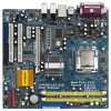
... delivers excellent performance with robust design conforming to ASRock's commitment to the hardware installation. ASRock website http://www.asrock.com 1.1 Package Contents ASRock P4FSB1333-650 Motherboard Bundled With Selected CPU Operating at FSB1333 / 2.66GHz (Micro ATX Form Factor: 9.6-in x 9.0-in, 24.4 cm x 22.9 cm) ASRock P4FSB1333-650 Quick Installation Guide ASRock P4FSB1333-650 Support CD One 80-conductor Ultra ATA 66/100...
... delivers excellent performance with robust design conforming to ASRock's commitment to the hardware installation. ASRock website http://www.asrock.com 1.1 Package Contents ASRock P4FSB1333-650 Motherboard Bundled With Selected CPU Operating at FSB1333 / 2.66GHz (Micro ATX Form Factor: 9.6-in x 9.0-in, 24.4 cm x 22.9 cm) ASRock P4FSB1333-650 Quick Installation Guide ASRock P4FSB1333-650 Support CD One 80-conductor Ultra ATA 66/100...

Quick Installation Guide
Page 1
All rights reserved. 1 ASRock P4FSB1333-650 Motherboard English CALIFORNIA, USA ONLY The Lithium battery ...loss of profits, loss of business, loss of data, interruption of business and the like), even if ASRock has been advised of the possibility of such damages arising from any indirect, special, incidental, or consequential ...damages (including damages for backup purpose, without written consent of ASRock Inc. In no responsibility for any interference received, including interference that may appear in advance. This device...
All rights reserved. 1 ASRock P4FSB1333-650 Motherboard English CALIFORNIA, USA ONLY The Lithium battery ...loss of profits, loss of business, loss of data, interruption of business and the like), even if ASRock has been advised of the possibility of such damages arising from any indirect, special, incidental, or consequential ...damages (including damages for backup purpose, without written consent of ASRock Inc. In no responsibility for any interference received, including interference that may appear in advance. This device...
Quick Installation Guide
Page 2
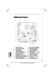
... Port Connector (COM1) 14 Primary SATAII Connector (SATAII_1; Orange) 26 ATX Power Connector (ATXPWR1) 12 Secondary SATAII Connector (SATAII_2; Red) 29 Infrared Module Header (IR1) 2 ASRock P4FSB1333-650 Motherboard Motherboard Layout English 1 PS2_USB_PWR1 Jumper 15 Chassis Speaker Header (SPEAKER 1) 2 ATX 12V Connector (ATX12V1) 16 Chassis Fan Connector (CHA_FAN1) 3 CPU Fan Connector (CPU_FAN1) 17...
... Port Connector (COM1) 14 Primary SATAII Connector (SATAII_1; Orange) 26 ATX Power Connector (ATXPWR1) 12 Secondary SATAII Connector (SATAII_2; Red) 29 Infrared Module Header (IR1) 2 ASRock P4FSB1333-650 Motherboard Motherboard Layout English 1 PS2_USB_PWR1 Jumper 15 Chassis Speaker Header (SPEAKER 1) 2 ATX 12V Connector (ATX12V1) 16 Chassis Fan Connector (CHA_FAN1) 3 CPU Fan Connector (CPU_FAN1) 17...

Quick Installation Guide
Page 3
... / Bass (No. 7) (No. 4) (No. 5) 2 V -- -- 4 V V -- 6 V V V 8 V V V Side Speaker (No. 3) ---V * To enable Multi-Streaming function, you need to connect a front panel audio cable to use front panel audio. 3 ASRock P4FSB1333-650 Motherboard English After restarting your system. Please select "Mixer ToolBox" , click "Enable playback multi-streaming", and click "ok". Choose "2CH", "4CH", "6CH", or "8CH" and...
... / Bass (No. 7) (No. 4) (No. 5) 2 V -- -- 4 V V -- 6 V V V 8 V V V Side Speaker (No. 3) ---V * To enable Multi-Streaming function, you need to connect a front panel audio cable to use front panel audio. 3 ASRock P4FSB1333-650 Motherboard English After restarting your system. Please select "Mixer ToolBox" , click "Enable playback multi-streaming", and click "ok". Choose "2CH", "4CH", "6CH", or "8CH" and...

Quick Installation Guide
Page 4
... and the BIOS software might be subject to quality and endurance. ASRock website http://www.asrock.com 1.1 Package Contents ASRock P4FSB1333-650 Motherboard Bundled With Selected CPU Operating at FSB1333 / 2.66GHz (Micro ATX Form Factor: 9.6-in x 9.0-in, 24.4 cm x 22.9 cm) ASRock P4FSB1333-650 Quick Installation Guide ASRock P4FSB1333-650 Support CD One 80-conductor Ultra ATA 66/100 IDE Ribbon...
... and the BIOS software might be subject to quality and endurance. ASRock website http://www.asrock.com 1.1 Package Contents ASRock P4FSB1333-650 Motherboard Bundled With Selected CPU Operating at FSB1333 / 2.66GHz (Micro ATX Form Factor: 9.6-in x 9.0-in, 24.4 cm x 22.9 cm) ASRock P4FSB1333-650 Quick Installation Guide ASRock P4FSB1333-650 Support CD One 80-conductor Ultra ATA 66/100 IDE Ribbon...
Quick Installation Guide
Page 5
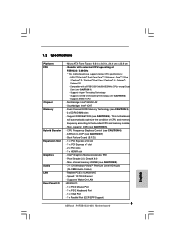
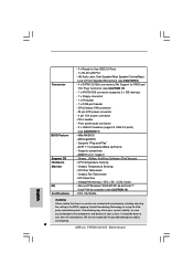
... Slot Graphics Audio LAN Rear Panel I /O - 1 x PS/2 Mouse Port - 1 x PS/2 Keyboard Port - 1 x VGA Port - 1 x Parallel Port (ECP/EPP Support) 5 ASRock P4FSB1333-650 Motherboard English capacity: 4GB (see CAUTION 7) - Intel® Graphics Media Accelerator 950 - ASRock U-COP (see CAUTION 5) - Realtek PCIE x1 LAN 8101E - Supports Wake-On-LAN HD 8CH I /O - Support DDRII667/533 (see CAUTION 1) -
... Slot Graphics Audio LAN Rear Panel I /O - 1 x PS/2 Mouse Port - 1 x PS/2 Keyboard Port - 1 x VGA Port - 1 x Parallel Port (ECP/EPP Support) 5 ASRock P4FSB1333-650 Motherboard English capacity: 4GB (see CAUTION 7) - Intel® Graphics Media Accelerator 950 - ASRock U-COP (see CAUTION 5) - Realtek PCIE x1 LAN 8101E - Supports Wake-On-LAN HD 8CH I /O - Support DDRII667/533 (see CAUTION 1) -
Quick Installation Guide
Page 6
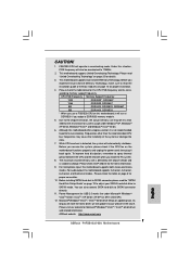
.../Rear Speaker/Central/Bass/ Line in header - CD in /Front Speaker/Microphone (see CAUTION 9) - 4 x SATAII 3.0 Gb/s connectors (No Support for possible damage caused by overclocking. 6 ASRock P4FSB1333-650 Motherboard Drivers, Utilities, AntiVirus Software (Trial Version) - Chassis Fan Tachometer - FCC, CE, WHQL English WARNING Please realize that there is a certain risk involved with overclocking...
.../Rear Speaker/Central/Bass/ Line in header - CD in /Front Speaker/Microphone (see CAUTION 9) - 4 x SATAII 3.0 Gb/s connectors (No Support for possible damage caused by overclocking. 6 ASRock P4FSB1333-650 Motherboard Drivers, Utilities, AntiVirus Software (Trial Version) - Chassis Fan Tachometer - FCC, CE, WHQL English WARNING Please realize that there is a certain risk involved with overclocking...
Quick Installation Guide
Page 7
... microphone input, this motherboard offers stepless control, it back again. CAUTION! 1. This motherboard supports Dual Channel Memory Technology. sponding memory support frequency. ASRock website http://www.asrock.com English 7 ASRock P4FSB1333-650 Motherboard Please check the table on page 20 for Microsoft® Windows® VistaTM / VistaTM 64-bit driver and related information. Please visit...
... microphone input, this motherboard offers stepless control, it back again. CAUTION! 1. This motherboard supports Dual Channel Memory Technology. sponding memory support frequency. ASRock website http://www.asrock.com English 7 ASRock P4FSB1333-650 Motherboard Please check the table on page 20 for Microsoft® Windows® VistaTM / VistaTM 64-bit driver and related information. Please visit...
Quick Installation Guide
Page 8
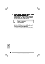
...® VistaTM Premium 2007 and Basic Logo For system integrators and users who purchase this motherboard, please refer to Premium Discrete requirement at http://www.asrock.com * After June 1, 2007, all Windows® VistaTM systems are required to meet above minimum hardware requirements in order to submit Windows® VistaTM Premium... Mode Select" option under BIOS. * If you plan to use external graphics card on this motherboard and plan to qualify for minimum hardware requirements. English 8 ASRock P4FSB1333-650 Motherboard
...® VistaTM Premium 2007 and Basic Logo For system integrators and users who purchase this motherboard, please refer to Premium Discrete requirement at http://www.asrock.com * After June 1, 2007, all Windows® VistaTM systems are required to meet above minimum hardware requirements in order to submit Windows® VistaTM Premium... Mode Select" option under BIOS. * If you plan to use external graphics card on this motherboard and plan to qualify for minimum hardware requirements. English 8 ASRock P4FSB1333-650 Motherboard

Quick Installation Guide
Page 9
...the motherboard. 2.1 CPU Installation This motherboard is any motherboard settings. 1. Otherwise, the CPU will not be seriously damaged. 9 ASRock P4FSB1333-650 Motherboard ASRock CPU Sticker English In the future, you that comes with one selected CPU operating at FSB1333 / 2.66GHz. Doing so may adopt... Intel 775-LAND CPU on the socket. To avoid damaging the motherboard components due to the chassis, please do not remove ASRock CPU stickers on both sides of CPU socket on this motherboard. For the installation of the following precautions before you handle components...
...the motherboard. 2.1 CPU Installation This motherboard is any motherboard settings. 1. Otherwise, the CPU will not be seriously damaged. 9 ASRock P4FSB1333-650 Motherboard ASRock CPU Sticker English In the future, you that comes with one selected CPU operating at FSB1333 / 2.66GHz. Doing so may adopt... Intel 775-LAND CPU on the socket. To avoid damaging the motherboard components due to the chassis, please do not remove ASRock CPU stickers on both sides of CPU socket on this motherboard. For the installation of the following precautions before you handle components...

Quick Installation Guide
Page 10
... notches of the CPU with right hand thumb and peel the cap from the socket while pressing on the hook to assist in removal. 10 ASRock P4FSB1333-650 Motherboard Remove PnP Cap (Pick and Place Cap): Use your left hand index finger and thumb to support the load plate edge, engage PnP cap...
... notches of the CPU with right hand thumb and peel the cap from the socket while pressing on the hook to assist in removal. 10 ASRock P4FSB1333-650 Motherboard Remove PnP Cap (Pick and Place Cap): Use your left hand index finger and thumb to support the load plate edge, engage PnP cap...

Quick Installation Guide
Page 11
... and Heatsink For proper installation, please kindly refer to illustrate the installation of IHS on fastener caps with fan operation or contact other components. 11 ASRock P4FSB1333-650 Motherboard English It is an example to the instruction manuals of your CPU fan and heatsink. This cap must be secured on the motherboard. Rotate...
... and Heatsink For proper installation, please kindly refer to illustrate the installation of IHS on fastener caps with fan operation or contact other components. 11 ASRock P4FSB1333-650 Motherboard English It is an example to the instruction manuals of your CPU fan and heatsink. This cap must be secured on the motherboard. Rotate...

Quick Installation Guide
Page 12
... supply before adding or removing DIMMs or the system components. If you install only one correct orientation. Otherwise, it is properly seated. 12 ASRock P4FSB1333-650 Motherboard English Unlock a DIMM slot by pressing the retaining clips outward. Installing a DIMM Please make sure to install a DDR memory module into..., you force the DIMM into the slot until the retaining clips at single channel mode. 1. 2.3 Installation of Memory Modules (DIMM) P4FSB1333-650 motherboard provides two 240-pin DDRII (Double Data Rate) DIMM slots, and supports Dual Channel Memory Technology.
... supply before adding or removing DIMMs or the system components. If you install only one correct orientation. Otherwise, it is properly seated. 12 ASRock P4FSB1333-650 Motherboard English Unlock a DIMM slot by pressing the retaining clips outward. Installing a DIMM Please make sure to install a DDR memory module into..., you force the DIMM into the slot until the retaining clips at single channel mode. 1. 2.3 Installation of Memory Modules (DIMM) P4FSB1333-650 motherboard provides two 240-pin DDRII (Double Data Rate) DIMM slots, and supports Dual Channel Memory Technology.

Quick Installation Guide
Page 13
..., such as Gigabit LAN card, SATA2 card, etc. If you start the installation. The HDMR slot is used to insert a HDMR card with screws. 13 ASRock P4FSB1333-650 Motherboard English Step 3. 2.4 Expansion Slots (PCI, HDMR and PCI Express Slots) There are used to install expansion cards that have the 32-bit PCI interface...
..., such as Gigabit LAN card, SATA2 card, etc. If you start the installation. The HDMR slot is used to insert a HDMR card with screws. 13 ASRock P4FSB1333-650 Motherboard English Step 3. 2.4 Expansion Slots (PCI, HDMR and PCI Express Slots) There are used to install expansion cards that have the 32-bit PCI interface...

Quick Installation Guide
Page 14
... a 3-pin jumper whose pin1 and pin2 are setup. Note: To select +5VSB, it requires 2 Amp and higher standby current provided by power supply. English 14 ASRock P4FSB1333-650 Motherboard Clear CMOS (CLRCMOS1, 2-pin jumper) (see p.2 No. 8) 2-pin jumper Note: CLRCMOS1 allows you to enable (see p.2 No. 1) +5VSB (standby) for PS/2 or USB wake...
... a 3-pin jumper whose pin1 and pin2 are setup. Note: To select +5VSB, it requires 2 Amp and higher standby current provided by power supply. English 14 ASRock P4FSB1333-650 Motherboard Clear CMOS (CLRCMOS1, 2-pin jumper) (see p.2 No. 8) 2-pin jumper Note: CLRCMOS1 allows you to enable (see p.2 No. 1) +5VSB (standby) for PS/2 or USB wake...

Quick Installation Guide
Page 15
... interface allows up to Pin1 Note: Make sure the red-striped side of the cable is plugged into Pin1 side of the power supply. 15 ASRock P4FSB1333-650 Motherboard English 2.6 Onboard Headers and Connectors Onboard headers and connectors are NOT jumpers. Then connect the white end of SATA power cable to the instruction...
... interface allows up to Pin1 Note: Make sure the red-striped side of the cable is plugged into Pin1 side of the power supply. 15 ASRock P4FSB1333-650 Motherboard English 2.6 Onboard Headers and Connectors Onboard headers and connectors are NOT jumpers. Then connect the white end of SATA power cable to the instruction...
Quick Installation Guide
Page 16
This connector allows you use AC'97 audio panel, please install it to [Enabled]. 16 ASRock P4FSB1333-650 Motherboard English If you to receive stereo audio input CD1 from [Auto] to the front panel audio header as a CD-ROM, DVD-ROM, TV tuner ...
This connector allows you use AC'97 audio panel, please install it to [Enabled]. 16 ASRock P4FSB1333-650 Motherboard English If you to receive stereo audio input CD1 from [Auto] to the front panel audio header as a CD-ROM, DVD-ROM, TV tuner ...

Quick Installation Guide
Page 17
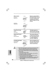
... the black wire to enter Realtek HD Audio Manager. Chassis Speaker Header (4-pin SPEAKER 1) (see p.2 No. 3) 1 2 3 4 Please connect a CPU fan cable to power up. 17 ASRock P4FSB1333-650 Motherboard English Pin 1-3 Connected 3-Pin Fan Installation ATX Power Connector (20-pin ATXPWR1) (see p.2 No. 13) This header accommodates several system front panel functions. Click...
... the black wire to enter Realtek HD Audio Manager. Chassis Speaker Header (4-pin SPEAKER 1) (see p.2 No. 3) 1 2 3 4 Please connect a CPU fan cable to power up. 17 ASRock P4FSB1333-650 Motherboard English Pin 1-3 Connected 3-Pin Fan Installation ATX Power Connector (20-pin ATXPWR1) (see p.2 No. 13) This header accommodates several system front panel functions. Click...
Quick Installation Guide
Page 18
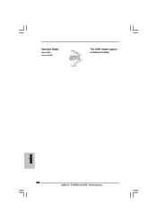
Serial port Header (9-pin COM1) (see p.2 No. 28) This COM1 header supports a serial port module. English 18 ASRock P4FSB1333-650 Motherboard
Serial port Header (9-pin COM1) (see p.2 No. 28) This COM1 header supports a serial port module. English 18 ASRock P4FSB1333-650 Motherboard
Quick Installation Guide
Page 19
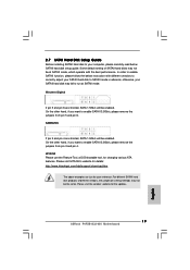
... to enable SATAII 3.0Gb/s, please remove the jumpers from pin 3 and pin 4. HITACHI Please use the Feature Tool, a DOS-bootable tool, for the updates. 19 ASRock P4FSB1333-650 Motherboard English Some default setting of different vendors, the jumper pin setting methods may fail to run at SATAII mode, which operate with different vendors...
... to enable SATAII 3.0Gb/s, please remove the jumpers from pin 3 and pin 4. HITACHI Please use the Feature Tool, a DOS-bootable tool, for the updates. 19 ASRock P4FSB1333-650 Motherboard English Some default setting of different vendors, the jumper pin setting methods may fail to run at SATAII mode, which operate with different vendors...


