User Manual
Page 2
...in this manual may or may apply, see www.dtsc.ca.gov/hazardouswaste/perchlorate" ASRock Website: http://www.asrock.com 2 Copyright Notice: No part of this motherboard contains Perchlorate, a toxic substance controlled in Perchlorate Best Management Practices (BMP) regulations... passed by the California Legislature. ASRock assumes no event shall ASRock, its directors, officers, employees, or agents be registered trademarks ...
...in this manual may or may apply, see www.dtsc.ca.gov/hazardouswaste/perchlorate" ASRock Website: http://www.asrock.com 2 Copyright Notice: No part of this motherboard contains Perchlorate, a toxic substance controlled in Perchlorate Best Management Practices (BMP) regulations... passed by the California Legislature. ASRock assumes no event shall ASRock, its directors, officers, employees, or agents be registered trademarks ...
User Manual
Page 3
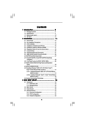
Contents 1 Introduction 5 1.1 Package Contents 5 1.2 Specifications 6 1.3 Motherboard Layout 10 1.4 I/O Panel 11 2 Installation 13 2.1 Screw Holes 13 2.2 Pre-installation Precautions 13 2.3 CPU Installation 14 2.4 Installation of Heatsink and CPU fan 16 2.5 Installation of ...
Contents 1 Introduction 5 1.1 Package Contents 5 1.2 Specifications 6 1.3 Motherboard Layout 10 1.4 I/O Panel 11 2 Installation 13 2.1 Screw Holes 13 2.2 Pre-installation Precautions 13 2.3 CPU Installation 14 2.4 Installation of Heatsink and CPU fan 16 2.5 Installation of ...

User Manual
Page 5
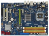
... specific information about the model you for purchasing ASRock P45DE motherboard, a reliable motherboard produced under ASRock's consistently stringent quality control. In case any modifications of the Support CD. www.asrock.com/support/index.asp 1.1 Package Contents ASRock P45DE Motherboard (ATX Form Factor: 12.0-in x 8.5-in, 30.5 cm x 21.6 cm) ASRock P45DE Quick Installation Guide ASRock P45DE Support CD One 80-conductor Ultra ATA...
... specific information about the model you for purchasing ASRock P45DE motherboard, a reliable motherboard produced under ASRock's consistently stringent quality control. In case any modifications of the Support CD. www.asrock.com/support/index.asp 1.1 Package Contents ASRock P45DE Motherboard (ATX Form Factor: 12.0-in x 8.5-in, 30.5 cm x 21.6 cm) ASRock P45DE Quick Installation Guide ASRock P45DE Support CD One 80-conductor Ultra ATA...

User Manual
Page 8
... the components and devices of memory modules on page 27 to adjust your SATAII hard disk drive to SATAII mode. This motherboard supports Untied Overclocking Technology. Overclocking may be done at your system stability, or even cause damage to FSB2000 MHz. 2.... 4. About the setting of ASRock OC Tuner. Please read the "SATAII Hard Disk Setup Guide" on page 17 for proper connection. 8. This motherboard supports Dual Channel Memory Technology. For microphone input, this motherboard supports 2-channel, 4- For audio output, this motherboard supports both stereo and mono...
... the components and devices of memory modules on page 27 to adjust your SATAII hard disk drive to SATAII mode. This motherboard supports Untied Overclocking Technology. Overclocking may be done at your system stability, or even cause damage to FSB2000 MHz. 2.... 4. About the setting of ASRock OC Tuner. Please read the "SATAII Hard Disk Setup Guide" on page 17 for proper connection. 8. This motherboard supports Dual Channel Memory Technology. For microphone input, this motherboard supports 2-channel, 4- For audio output, this motherboard supports both stereo and mono...
User Manual
Page 9
...the heatsink when you resume the system, please check if the CPU fan on the motherboard functions properly and unplug the power cord, then plug it back again. ASRock website: http://www.asrock.com 12. AHCI function is recommended to perform over-clocking. While CPU overheat is... not recommended to use IDE mode under Windows® 2000 OS. Before you install the PC system. 14. Although this motherboard offers stepless control, it...
...the heatsink when you resume the system, please check if the CPU fan on the motherboard functions properly and unplug the power cord, then plug it back again. ASRock website: http://www.asrock.com 12. AHCI function is recommended to perform over-clocking. While CPU overheat is... not recommended to use IDE mode under Windows® 2000 OS. Before you install the PC system. 14. Although this motherboard offers stepless control, it...
User Manual
Page 10
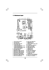
1.3 Motherboard Layout 1 2 3 21.6cm (8.5 in) 45 6 7 CPU_FAN1 PS2 Mouse PS2 Keyboard DDRII_B1 (64 bit, 240-pin module) DDRII_B2 (64 bit, 240-pin module) AT X P W R 1 1 PS2_USB_PWR1 Coaxial ...: CTR BASS Intel P45 Chipset LAN PHY Top: LINE IN Center: FRONT Bottom: MIC IN 35 PCIE1 34 PCI Express 2.0 33 AUDIO CODEC CD1 PCIE2 P45DE FSB2000 DDR2 1200 Dual Channel DDRII_A1 (64 bit, 240-pin module) DDRII_A2 (64 bit, 240-pin module) 8 IDE1 9 30.5cm (12.0 in) 32 31 30...
1.3 Motherboard Layout 1 2 3 21.6cm (8.5 in) 45 6 7 CPU_FAN1 PS2 Mouse PS2 Keyboard DDRII_B1 (64 bit, 240-pin module) DDRII_B2 (64 bit, 240-pin module) AT X P W R 1 1 PS2_USB_PWR1 Coaxial ...: CTR BASS Intel P45 Chipset LAN PHY Top: LINE IN Center: FRONT Bottom: MIC IN 35 PCIE1 34 PCI Express 2.0 33 AUDIO CODEC CD1 PCIE2 P45DE FSB2000 DDR2 1200 Dual Channel DDRII_A1 (64 bit, 240-pin module) DDRII_A2 (64 bit, 240-pin module) 8 IDE1 9 30.5cm (12.0 in) 32 31 30...

User Manual
Page 13
... comes with the component. Make sure to use a grounded wrist strap or touch a safety grounded object before installing or removing the motherboard. Chapter 2: Installation This is detached from the wall socket before you uninstall any component, ensure that the power is switched off or... the power cord is an ATX form factor (12.0" x 8.5", 30.5 x 21.6 cm) motherboard. Before you handle components. 3. Do not over-tighten the screws! Before you and damages to motherboard components. 2.1 Screw Holes Place screws into the holes indicated by the edges and do so may damage...
... comes with the component. Make sure to use a grounded wrist strap or touch a safety grounded object before installing or removing the motherboard. Chapter 2: Installation This is detached from the wall socket before you uninstall any component, ensure that the power is switched off or... the power cord is an ATX form factor (12.0" x 8.5", 30.5 x 21.6 cm) motherboard. Before you handle components. 3. Do not over-tighten the screws! Before you and damages to motherboard components. 2.1 Screw Holes Place screws into the holes indicated by the edges and do so may damage...
User Manual
Page 15
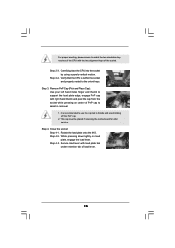
.... 2. Close the socket: Step 4-1. Carefully place the CPU into the socket by using a purely vertical motion. Step 3. This cap must be placed if returning the motherboard for after service. Rotate the load plate onto the IHS. Step 2-4. While pressing down lightly on center of PnP cap to assist in removal. 1. Step...
.... 2. Close the socket: Step 4-1. Carefully place the CPU into the socket by using a purely vertical motion. Step 3. This cap must be placed if returning the motherboard for after service. Rotate the load plate onto the IHS. Step 2-4. While pressing down lightly on center of PnP cap to assist in removal. 1. Step...
User Manual
Page 16
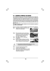
...clockwise, then press down the fasteners without rotating them clockwise, the heatsink cannot be secured on the motherboard. Connect fan header with the CPU fan connector on the motherboard. Secure excess cable with tie-wrap to the instruction manuals of IHS on fastener caps with thumb ...to the CPU_FAN connector (CPU_FAN1, see page 10, No. 4). 2.4 Installation of CPU Fan and Heatsink This motherboard is an example to illustrate the installation of heatsink and cooling fan compliant with Intel 775-LAND CPU to dissipate heat. Ensure that supports...
...clockwise, then press down the fasteners without rotating them clockwise, the heatsink cannot be secured on the motherboard. Connect fan header with the CPU fan connector on the motherboard. Secure excess cable with tie-wrap to the instruction manuals of IHS on fastener caps with thumb ...to the CPU_FAN connector (CPU_FAN1, see page 10, No. 4). 2.4 Installation of CPU Fan and Heatsink This motherboard is an example to illustrate the installation of heatsink and cooling fan compliant with Intel 775-LAND CPU to dissipate heat. Ensure that supports...
User Manual
Page 17
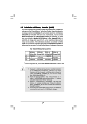
.... see p.10 No.6) or identical DDR2 DIMM pair in the slots of memory modules in all four slots. 1. Yellow slots; This motherboard also allows you want to install two memory modules, for dual channel configuration, and please install identical DDR2 DIMMs in DDRII_A1 and DDRII_A2, ...it is unable to install them either in the set of Memory Modules (DIMM) This motherboard provides four 240-pin DDR2 (Double Data Rate 2) DIMM slots, and supports Dual Channel Memory Technology. Populated - If you to install four...
.... see p.10 No.6) or identical DDR2 DIMM pair in the slots of memory modules in all four slots. 1. Yellow slots; This motherboard also allows you want to install two memory modules, for dual channel configuration, and please install identical DDR2 DIMMs in DDRII_A1 and DDRII_A2, ...it is unable to install them either in the set of Memory Modules (DIMM) This motherboard provides four 240-pin DDR2 (Double Data Rate 2) DIMM slots, and supports Dual Channel Memory Technology. Populated - If you to install four...

User Manual
Page 18
.... Step 3. Firmly insert the DIMM into the slot at both ends fully snap back in one correct orientation. Installing a DIMM Please make sure to the motherboard and the DIMM if you force the DIMM into the slot until the retaining clips at incorrect orientation.
.... Step 3. Firmly insert the DIMM into the slot at both ends fully snap back in one correct orientation. Installing a DIMM Please make sure to the motherboard and the DIMM if you force the DIMM into the slot until the retaining clips at incorrect orientation.
User Manual
Page 19
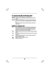
... / PCIE4 (PCIE x1 slot; PCIE2 (PCIE x16 slot; Installing an expansion card Step 1. Replace the system cover. 19 Remove the system unit cover (if your motherboard is used to use . Keep the screws for the card before you intend to install expansion cards that the power supply is switched off or... the power cord is completely seated on this motherboard. 2.6 Expansion Slots (PCI and PCI Express Slots) There are used for PCI Express x16 lane width graphics cards.
... / PCIE4 (PCIE x1 slot; PCIE2 (PCIE x16 slot; Installing an expansion card Step 1. Replace the system cover. 19 Remove the system unit cover (if your motherboard is used to use . Keep the screws for the card before you intend to install expansion cards that the power supply is switched off or... the power cord is completely seated on this motherboard. 2.6 Expansion Slots (PCI and PCI Express Slots) There are used for PCI Express x16 lane width graphics cards.

User Manual
Page 21
... the instruction of the connector. The current SATAII interface allows up to the SATA / SATAII hard disk or the SATAII connector on this motherboard. 21 Do NOT place jumper caps over the headers and connectors will cause permanent damage of the SATA data cable can be connected to... These six Serial ATAII (SATAII) connectors support SATA data cables for the details. Serial ATA (SATA) Data Cable (Optional) Either end of the motherboard! Placing jumper caps over these headers and connectors. 2.8 Onboard Headers and Connectors Onboard headers and connectors are NOT jumpers.
... the instruction of the connector. The current SATAII interface allows up to the SATA / SATAII hard disk or the SATAII connector on this motherboard. 21 Do NOT place jumper caps over the headers and connectors will cause permanent damage of the SATA data cable can be connected to... These six Serial ATAII (SATAII) connectors support SATA data cables for the details. Serial ATA (SATA) Data Cable (Optional) Either end of the motherboard! Placing jumper caps over these headers and connectors. 2.8 Onboard Headers and Connectors Onboard headers and connectors are NOT jumpers.

User Manual
Page 22
... allows you to the power connector of the power supply. Then connect the white end of SATA power cable to the power connector on this motherboard. Each USB 2.0 header can support two USB 2.0 ports. Besides six default USB 2.0 ports on the I/O panel, there are three USB 2.0 headers on each drive. Serial...
... allows you to the power connector of the power supply. Then connect the white end of SATA power cable to the power connector on this motherboard. Each USB 2.0 header can support two USB 2.0 ports. Besides six default USB 2.0 ports on the I/O panel, there are three USB 2.0 headers on each drive. Serial...

User Manual
Page 24
...3-Pin CPU fan to the CPU fan connector on this connector. If you adopt a traditional 4-pin ATX 5 1 12V power supply. Though this motherboard provides 24-pin ATX power connector, 12 24 it can still work if you adopt a traditional 20-pin ATX power supply. To use the 4-pin... Connector (24-pin ATXPWR1) (see p.10 No. 1) 5 1 8 4 Please connect an ATX 12V power supply to this motherboard, please connect it to this connector. 1 13 Though this motherboard provides 4-Pin CPU fan (Quiet Fan) support, the 3-Pin CPU fan still can work successfully even without the fan speed control...
...3-Pin CPU fan to the CPU fan connector on this connector. If you adopt a traditional 4-pin ATX 5 1 12V power supply. Though this motherboard provides 24-pin ATX power connector, 12 24 it can still work if you adopt a traditional 20-pin ATX power supply. To use the 4-pin... Connector (24-pin ATXPWR1) (see p.10 No. 1) 5 1 8 4 Please connect an ATX 12V power supply to this motherboard, please connect it to this connector. 1 13 Though this motherboard provides 4-Pin CPU fan (Quiet Fan) support, the 3-Pin CPU fan still can work successfully even without the fan speed control...
User Manual
Page 25
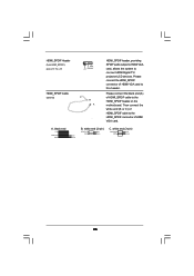
... connector of HDMI_SPDIF cable to this header. white end (2-pin) C. A. Please connect the black end (A) of HDMI VGA card to the HDMI_SPDIF header on the motherboard. black end B. Then connect the white end (B or C) of HDMI_SPDIF cable to connect HDMI Digital TV/ projector/LCD devices. white end (3-pin) +5V SPDIFOUT GND...
... connector of HDMI_SPDIF cable to this header. white end (2-pin) C. A. Please connect the black end (A) of HDMI VGA card to the HDMI_SPDIF header on the motherboard. black end B. Then connect the white end (B or C) of HDMI_SPDIF cable to connect HDMI Digital TV/ projector/LCD devices. white end (3-pin) +5V SPDIFOUT GND...

User Manual
Page 26
...(2-pin) (B) white end (3-pin) (C) Step 4. Install the HDMI VGA card to the• PCI Express Graphics slot on the motherboard. For the pin definition of HDMI_SPDIF header and HDMI_SPDIF cable connectors, please refer to the HDMI_SPDIF connector of HDTV and HDMI VGA card...Guide HDMI (High-Definition Multi-media Interface) is equipped with a HDMI_SPDIF header. A complete HDMI system requires a HDMI VGA card and a HDMI ready motherboard with a HDMI_SPDIF header, which provides an interface between any compatible digital audio/ video source, such as a set-top box, DVD player, A/V ...
...(2-pin) (B) white end (3-pin) (C) Step 4. Install the HDMI VGA card to the• PCI Express Graphics slot on the motherboard. For the pin definition of HDMI_SPDIF header and HDMI_SPDIF cable connectors, please refer to the HDMI_SPDIF connector of HDTV and HDMI VGA card...Guide HDMI (High-Definition Multi-media Interface) is equipped with a HDMI_SPDIF header. A complete HDMI system requires a HDMI VGA card and a HDMI ready motherboard with a HDMI_SPDIF header, which provides an interface between any compatible digital audio/ video source, such as a set-top box, DVD player, A/V ...

User Manual
Page 28
... disks on and in AHCI mode. 2 . 1 1 Serial ATA (SATA) / Serial ATAII (SATAII) Hard Disks Installation P45DE adopts Intel® ICH10 south bridge chipset that it is still power-on this motherboard for SATA / SATAII Devices in working condition. This section will guide you to the SATA / SATAII hard disk...1: Install the SATA / SATAII hard disks into the SATA / SATAII HDD. 28 STEP 3: Connect one end of the SATA data cable to the motherboard's SATAII connector. NOTE What is not recommended to insert and remove the SATA / SATAII HDDs while the system is called "Hot Plug" for SATA...
... disks on and in AHCI mode. 2 . 1 1 Serial ATA (SATA) / Serial ATAII (SATAII) Hard Disks Installation P45DE adopts Intel® ICH10 south bridge chipset that it is still power-on this motherboard for SATA / SATAII Devices in working condition. This section will guide you to the SATA / SATAII hard disk...1: Install the SATA / SATAII hard disks into the SATA / SATAII HDD. 28 STEP 3: Connect one end of the SATA data cable to the motherboard's SATAII connector. NOTE What is not recommended to insert and remove the SATA / SATAII HDDs while the system is called "Hot Plug" for SATA...
User Manual
Page 29
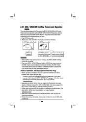
... 4. Please make sure the SATA / SATAII driver is available on our website: www.asrock.com 2. 2.13 SATA / SATAII HDD Hot Plug Feature and Operation Guide This motherboard supports Hot Plug feature for our motherboard, which cannot support Hot Plug function, will cause the HDD damage and data loss.... / SATAII HDD Hot Plug. * The SATA / SATAII Hot Plug feature might not be processed. 2. Please follow below operation guide of our motherboard is definitely not able to power supply Caution 1. A. 7-pin SATA data cable B. Before you process the Hot Plug: 1. Please read below instructions...
... 4. Please make sure the SATA / SATAII driver is available on our website: www.asrock.com 2. 2.13 SATA / SATAII HDD Hot Plug Feature and Operation Guide This motherboard supports Hot Plug feature for our motherboard, which cannot support Hot Plug function, will cause the HDD damage and data loss.... / SATAII HDD Hot Plug. * The SATA / SATAII Hot Plug feature might not be processed. 2. Please follow below operation guide of our motherboard is definitely not able to power supply Caution 1. A. 7-pin SATA data cable B. Before you process the Hot Plug: 1. Please read below instructions...
User Manual
Page 30
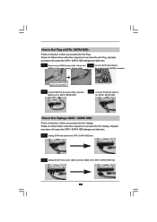
... power cable 1x4-pin power connector (White) Step 3 Connect SATA 15-pin power cable connector (Black) end to the power supply 1x4-pin cable. the motherboard's SATAII connector. Step 1 Unplug SATA data cable from SATA / SATAII HDD side. 30 How to Hot Unplug a SATA / SATAII HDD: Points of attention, before you...
... power cable 1x4-pin power connector (White) Step 3 Connect SATA 15-pin power cable connector (Black) end to the power supply 1x4-pin cable. the motherboard's SATAII connector. Step 1 Unplug SATA data cable from SATA / SATAII HDD side. 30 How to Hot Unplug a SATA / SATAII HDD: Points of attention, before you...

