User Manual
Page 2
...the possibility of such damages arising from any interference received, including interference that may appear in this manual. ASRock assumes no event shall ASRock, its directors, officers, employees, or agents be registered trademarks or copyrights of their respective companies, and... any defect or error in Perchlorate Best Management Practices (BMP) regulations passed by ASRock. Operation is subject to infringe. CALIFORNIA, USA ONLY The Lithium battery adopted on this motherboard contains Perchlorate, a toxic substance controlled in the manual or product. Products and ...
...the possibility of such damages arising from any interference received, including interference that may appear in this manual. ASRock assumes no event shall ASRock, its directors, officers, employees, or agents be registered trademarks or copyrights of their respective companies, and... any defect or error in Perchlorate Best Management Practices (BMP) regulations passed by ASRock. Operation is subject to infringe. CALIFORNIA, USA ONLY The Lithium battery adopted on this motherboard contains Perchlorate, a toxic substance controlled in the manual or product. Products and ...
User Manual
Page 3
Introduction 5 1.1 Package Contents 5 1.2 Specifications 6 1.3 Motherboard Layout (N68-VGS3 FX / N68-VS3 FX 11 1.4 I/O Panel (N68-VGS3 FX 12 1.5 I/O Panel (N68-VS3 FX 13 2 . BIOS SETUP UTILITY 30 3.1 Introduction 30 3.1.1 BIOS Menu Bar 30 3.1.2 Navigation Keys 31 3.2 Main Screen 31 3.3 OC Tweaker Screen 32 3.4 Advanced Screen 37 3.4.1 CPU ...
Introduction 5 1.1 Package Contents 5 1.2 Specifications 6 1.3 Motherboard Layout (N68-VGS3 FX / N68-VS3 FX 11 1.4 I/O Panel (N68-VGS3 FX 12 1.5 I/O Panel (N68-VS3 FX 13 2 . BIOS SETUP UTILITY 30 3.1 Introduction 30 3.1.1 BIOS Menu Bar 30 3.1.2 Navigation Keys 31 3.2 Main Screen 31 3.3 OC Tweaker Screen 32 3.4 Advanced Screen 37 3.4.1 CPU ...
User Manual
Page 5
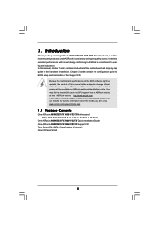
... to this manual occur, the updated version will be available on ASRock website as well. www.asrock.com/support/index.asp 1.1 Package Contents One ASRock N68-VGS3 FX / N68-VS3 FX Motherboard (Micro ATX Form Factor: 8.5-in x 7.0-in, 21.6 cm x 17.8 cm) One ASRock N68-VGS3 FX / N68-VS3 FX Quick Installation Guide One ASRock N68-VGS3 FX / N68-VS3 FX Support CD Two Serial ATA (SATA) Data Cables (Optional) One...
... to this manual occur, the updated version will be available on ASRock website as well. www.asrock.com/support/index.asp 1.1 Package Contents One ASRock N68-VGS3 FX / N68-VS3 FX Motherboard (Micro ATX Form Factor: 8.5-in x 7.0-in, 21.6 cm x 17.8 cm) One ASRock N68-VGS3 FX / N68-VS3 FX Quick Installation Guide One ASRock N68-VGS3 FX / N68-VS3 FX Support CD Two Serial ATA (SATA) Data Cables (Optional) One...
User Manual
Page 8
...information, please visit our website: http://www.asrock.com WARNING Please realize that UCC feature is supported with 64-bit CPU, there is defined by overclocking. We are not responsible for details. 5. This motherboard supports CPU up to 6MB, which means .../ XP. ASRock website http://www.asrock.com 3. Please be done at your system. This motherboard supports Untied Overclocking Technology. Please read the installation guide of the BIOS option "ASRock UCC", you need to 95W. This motherboard supports Dual Channel Memory Technology. ASRock website http://www.asrock.com 7. For...
...information, please visit our website: http://www.asrock.com WARNING Please realize that UCC feature is supported with 64-bit CPU, there is defined by overclocking. We are not responsible for details. 5. This motherboard supports CPU up to 6MB, which means .../ XP. ASRock website http://www.asrock.com 3. Please be done at your system. This motherboard supports Untied Overclocking Technology. Please read the installation guide of the BIOS option "ASRock UCC", you need to 95W. This motherboard supports Dual Channel Memory Technology. ASRock website http://www.asrock.com 7. For...
User Manual
Page 9
... utility developed by hardware monitor function and overclock your overclocking record under Windows® environment. It helps you to access ASRock Instant Flash. Please visit our website for the operation procedures of overclocking settings. Featuring an advanced proprietary hardware and software ... to SATAII connector, please read the "SATAII Hard Disk Setup Guide" on the same motherboard. 9 Please be noticed that delivers unparalleled power savings. ASRock website: http://www.asrock.com 12. You can update your friends! Please visit our website for the operation procedures...
... utility developed by hardware monitor function and overclock your overclocking record under Windows® environment. It helps you to access ASRock Instant Flash. Please visit our website for the operation procedures of overclocking settings. Featuring an advanced proprietary hardware and software ... to SATAII connector, please read the "SATAII Hard Disk Setup Guide" on the same motherboard. 9 Please be noticed that delivers unparalleled power savings. ASRock website: http://www.asrock.com 12. You can update your friends! Please visit our website for the operation procedures...
User Manual
Page 10
... While CPU overheat is the smart start page for a more personal Internet experience. ASRock APP Charger allows you - ASRock website: http://www.asrock.com/Feature/SmartView/index.asp 16. Although this motherboard offers stepless control, it can configure your application priority ideally and/or add new programs...to spray thermal grease between the CPU and the heatsink when you resume the system, please check if the CPU fan on -the-go. ASRock motherboards are currently transferring. 18. To use SmartView feature, please make sure your OS version is Windows® 7 / 7 64 bit / VistaTM...
... While CPU overheat is the smart start page for a more personal Internet experience. ASRock APP Charger allows you - ASRock website: http://www.asrock.com/Feature/SmartView/index.asp 16. Although this motherboard offers stepless control, it can configure your application priority ideally and/or add new programs...to spray thermal grease between the CPU and the heatsink when you resume the system, please check if the CPU fan on -the-go. ASRock motherboards are currently transferring. 18. To use SmartView feature, please make sure your OS version is Windows® 7 / 7 64 bit / VistaTM...
User Manual
Page 11
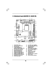
... (PCIE1) 23 Front Panel Audio Header (HD_AUDIO1, Lime) 24 ATX 12V Power Connector (ATX12V1) 25 AM3 CPU Socket 26 ATX Power Connector (ATXPWR1) 11 1.3 Motherboard Layout (N68-VGS3 FX / N68-VS3 FX) 26 USB 2.0 T: USB2 B: USB3 VGA1 PS2 Mouse PS2 Keyboard 1 2 3 17.8cm (7.0-in) Support 8-Core CPU 1 PS2_USB_PWR1 CPU_FAN1 1 USB_PWR2 DDR3_B1 (64 bit, 240-FpSin Bm8od0u0le...
... (PCIE1) 23 Front Panel Audio Header (HD_AUDIO1, Lime) 24 ATX 12V Power Connector (ATX12V1) 25 AM3 CPU Socket 26 ATX Power Connector (ATXPWR1) 11 1.3 Motherboard Layout (N68-VGS3 FX / N68-VS3 FX) 26 USB 2.0 T: USB2 B: USB3 VGA1 PS2 Mouse PS2 Keyboard 1 2 3 17.8cm (7.0-in) Support 8-Core CPU 1 PS2_USB_PWR1 CPU_FAN1 1 USB_PWR2 DDR3_B1 (64 bit, 240-FpSin Bm8od0u0le...
User Manual
Page 14
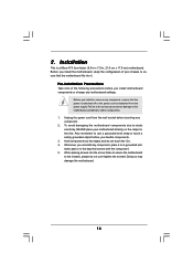
...is switched off or the power cord is a Micro ATX form factor (8.5-in x 7.0-in the bag that the motherboard fits into the screw holes to secure the motherboard to the motherboard, peripherals, and/or components. 1. Before you install or remove any component. 2. When placing screws into it on... the carpet or the like. Unplug the power cord from the power supply. Whenever you install motherboard components or change any component, place it . Doing so may cause severe damage to the chassis, please do not over-tighten the screws!...
...is switched off or the power cord is a Micro ATX form factor (8.5-in x 7.0-in the bag that the motherboard fits into the screw holes to secure the motherboard to the motherboard, peripherals, and/or components. 1. Before you install or remove any component. 2. When placing screws into it on... the carpet or the like. Unplug the power cord from the power supply. Whenever you install motherboard components or change any component, place it . Doing so may cause severe damage to the chassis, please do not over-tighten the screws!...
User Manual
Page 15
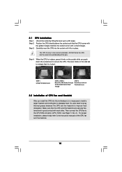
... the pins. For proper installation, please kindly refer to avoid bending of the CPU fan and the heatsink. 15 Carefully insert the CPU into this motherboard, it is necessary to install a larger heatsink and cooling fan to indicate that the CPU corner with the golden triangle matches the socket corner with...
... the pins. For proper installation, please kindly refer to avoid bending of the CPU fan and the heatsink. 15 Carefully insert the CPU into this motherboard, it is necessary to install a larger heatsink and cooling fan to indicate that the CPU corner with the golden triangle matches the socket corner with...
User Manual
Page 16
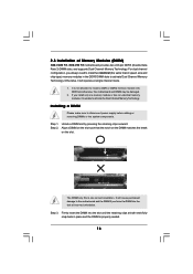
... in the DDR3 DIMM slots to disconnect power supply before adding or removing DIMMs or the system components. 2.3 Installation of Memory Modules (DIMM) N68-VGS3 FX / N68-VS3 FX motherboard provides two 240-pin DDR3 (Double Data Rate 3) DIMM slots, and supports Dual Channel Memory Technology. Align a DIMM on the slot such ... break notch break The DIMM only fits in one memory module or two non-identical memory modules, it will cause permanent damage to the motherboard and the DIMM if you always need to install two identical (the same brand, speed, size and chip-type) memory modules in place...
... in the DDR3 DIMM slots to disconnect power supply before adding or removing DIMMs or the system components. 2.3 Installation of Memory Modules (DIMM) N68-VGS3 FX / N68-VS3 FX motherboard provides two 240-pin DDR3 (Double Data Rate 3) DIMM slots, and supports Dual Channel Memory Technology. Align a DIMM on the slot such ... break notch break The DIMM only fits in one memory module or two non-identical memory modules, it will cause permanent damage to the motherboard and the DIMM if you always need to install two identical (the same brand, speed, size and chip-type) memory modules in place...
User Manual
Page 17
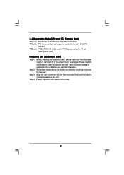
... 32-bit PCI interface. Keep the screws for PCI Express cards with the slot and press firmly until the card is completely seated on this motherboard. PCIE slot: PCIE1 (PCIE x16 slot) is used to install expansion cards that you start the installation. Fasten the card to use .
... 32-bit PCI interface. Keep the screws for PCI Express cards with the slot and press firmly until the card is completely seated on this motherboard. PCIE slot: PCIE1 (PCIE x16 slot) is used to install expansion cards that you start the installation. Fasten the card to use .
User Manual
Page 18
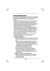
Connect the D-Sub monitor cable to this motherboard. 4. If you wish to display a large number on each monitor. Set up a multi monitor environment: 1. Right-click the display icon in the Display ...use multiple monitors with your primary monitor, and then select "Primary". Click "Extend my Windows desktop onto this motherboard. Set the "Screen Resolution" and "Color Quality" as Secondary. 2.5 Easy Multi Monitor Feature This motherboard supports Multi Monitor upgrade. Click the "Identify" button to be designated as appropriate for the second monitor. B....
Connect the D-Sub monitor cable to this motherboard. 4. If you wish to display a large number on each monitor. Set up a multi monitor environment: 1. Right-click the display icon in the Display ...use multiple monitors with your primary monitor, and then select "Primary". Click "Extend my Windows desktop onto this motherboard. Set the "Screen Resolution" and "Color Quality" as Secondary. 2.5 Easy Multi Monitor Feature This motherboard supports Multi Monitor upgrade. Click the "Identify" button to be designated as appropriate for the second monitor. B....
User Manual
Page 20
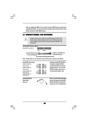
... 0.1): see p.11, No. 9) (SATAII_3 (PORT 1.0): see p.11, No. 11) (SATAII_4 (PORT 1.1): see p.11 No. 6) PIN1 IDE1 connect the blue end to the motherboard connect the black end to the IDE devices 80-conductor ATA 66/100/133 cable Note: Please refer to clear the CMOS when you just... you do the clear-CMOS action. 2.7 Onboard Headers and Connectors Onboard headers and connectors are NOT jumpers. If you need to the instruction of the motherboard! • Primary IDE connector (Blue) (39-pin IDE1, see p.11, No. 10) Serial ATA (SATA) Data Cable (Optional) SATAII_1 SATAII_2 (PORT 0.0) (...
... 0.1): see p.11, No. 9) (SATAII_3 (PORT 1.0): see p.11, No. 11) (SATAII_4 (PORT 1.1): see p.11 No. 6) PIN1 IDE1 connect the blue end to the motherboard connect the black end to the IDE devices 80-conductor ATA 66/100/133 cable Note: Please refer to clear the CMOS when you just... you do the clear-CMOS action. 2.7 Onboard Headers and Connectors Onboard headers and connectors are NOT jumpers. If you need to the instruction of the motherboard! • Primary IDE connector (Blue) (39-pin IDE1, see p.11, No. 10) Serial ATA (SATA) Data Cable (Optional) SATAII_1 SATAII_2 (PORT 0.0) (...
User Manual
Page 21
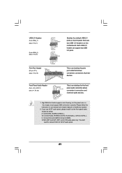
.... 21 Connect Mic_IN (MIC) to OUT2_L. Connect Audio_R (RIN) to OUT2_R and Audio_L (LIN) to MIC2_L. MIC_RET and OUT_RET are two USB 2.0 headers on this motherboard. If you use AC'97 audio panel, please install it to Ground (GND). Connect Ground (GND) to the front panel audio header as below: A. You...
.... 21 Connect Mic_IN (MIC) to OUT2_L. Connect Audio_R (RIN) to OUT2_R and Audio_L (LIN) to MIC2_L. MIC_RET and OUT_RET are two USB 2.0 headers on this motherboard. If you use AC'97 audio panel, please install it to Ground (GND). Connect Ground (GND) to the front panel audio header as below: A. You...
User Manual
Page 22
...functions. If you plan to connect the 3-Pin CPU fan to the CPU fan connector on this connector and match the black wire to this motherboard, please connect it can work if you adopt a traditional 20-pin ATX power supply. Please connect a chassis fan cable to the ground pin.... Though this connector and match the black wire to this motherboard provides 4-Pin CPU fan (Quiet Fan) support, the 3-Pin CPU fan still can still work successfully even without the fan speed control function. To...
...functions. If you plan to connect the 3-Pin CPU fan to the CPU fan connector on this connector and match the black wire to this motherboard, please connect it can work if you adopt a traditional 20-pin ATX power supply. Please connect a chassis fan cable to the ground pin.... Though this connector and match the black wire to this motherboard provides 4-Pin CPU fan (Quiet Fan) support, the 3-Pin CPU fan still can still work successfully even without the fan speed control function. To...
User Manual
Page 25
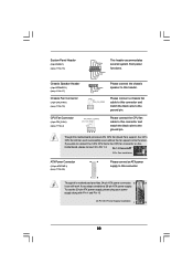
... Plug Function? This section will guide you to the SATA / SATAII hard disk. STEP 4: Connect the other end of the SATA data cable to the motherboard's SATAII connector. NOTE What is Hot Swap Function? STEP 3: Connect one end of the SATA data cable to the SATA / SATAII hard disk. 2 ... Serial ATA (SATA) / Serial ATAII (SATAII) hard disks and RAID functions. 2 . 9 Serial ATA (SATA) / Serial ATAII (SATAII) Hard Disks Installation This motherboard adopts NVIDIA® GeForce 7025 / nForce 630a chipset that it cannot perform Hot Plug if the OS has been installed into the drive bays of...
... Plug Function? This section will guide you to the SATA / SATAII hard disk. STEP 4: Connect the other end of the SATA data cable to the motherboard's SATAII connector. NOTE What is Hot Swap Function? STEP 3: Connect one end of the SATA data cable to the SATA / SATAII hard disk. 2 ... Serial ATA (SATA) / Serial ATAII (SATAII) hard disks and RAID functions. 2 . 9 Serial ATA (SATA) / Serial ATAII (SATAII) Hard Disks Installation This motherboard adopts NVIDIA® GeForce 7025 / nForce 630a chipset that it cannot perform Hot Plug if the OS has been installed into the drive bays of...
User Manual
Page 26
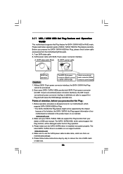
... 1. Please follow below instructions step by the chipset because of its limitation, the SATA / SATAII Hot Plug support information of our motherboard is indicated in RAID mode. Below operation procedure is installed into system properly. The SATA / SATAII HDD, which cannot support Hot Plug..., the IDE 1x4-pin conventional power connector interface is available on our website: www.asrock.com 2. 2.11 SATA / SATAII HDD Hot Plug Feature and Operation Guide This motherboard supports Hot Plug feature for our motherboard, which supports SATA / SATAII HDD Hot Plug. * The SATA / SATAII Hot...
... 1. Please follow below instructions step by the chipset because of its limitation, the SATA / SATAII Hot Plug support information of our motherboard is indicated in RAID mode. Below operation procedure is installed into system properly. The SATA / SATAII HDD, which cannot support Hot Plug..., the IDE 1x4-pin conventional power connector interface is available on our website: www.asrock.com 2. 2.11 SATA / SATAII HDD Hot Plug Feature and Operation Guide This motherboard supports Hot Plug feature for our motherboard, which supports SATA / SATAII HDD Hot Plug. * The SATA / SATAII Hot...
User Manual
Page 27
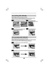
the motherboard's SATAII connector. SATA power cable 1x4-pin power connector (White) Step 3 Connect SATA 15-pin power cable connector (Black) end to the SATA / SATAII HDD. ...
the motherboard's SATAII connector. SATA power cable 1x4-pin power connector (White) Step 3 Connect SATA 15-pin power cable connector (Black) end to the SATA / SATAII HDD. ...
User Manual
Page 29
Therefore, CPU FSB is untied during overclocking, FSB enjoys better margin due to fixed PCI / PCIE buses. 2.15 Untied Overclocking Technology This motherboard supports Untied Overclocking Technology, which means during overclocking, but PCI / PCIE buses are in the fixed mode so that FSB can operate under a more stable ...
Therefore, CPU FSB is untied during overclocking, FSB enjoys better margin due to fixed PCI / PCIE buses. 2.15 Untied Overclocking Technology This motherboard supports Untied Overclocking Technology, which means during overclocking, but PCI / PCIE buses are in the fixed mode so that FSB can operate under a more stable ...
User Manual
Page 30
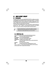
... press to locate and load the Operating System Security To set up the computer. You may also restart by pressing the reset button on the motherboard stores the BIOS SETUP UTILITY. You may run the BIOS SETUP UTILITY when you see on your system.
... press to locate and load the Operating System Security To set up the computer. You may also restart by pressing the reset button on the motherboard stores the BIOS SETUP UTILITY. You may run the BIOS SETUP UTILITY when you see on your system.

