User Manual
Page 6
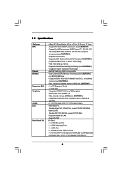
...Socket AM3+ processors (see CAUTION 3) - Supports AMD's Cool 'n' QuietTM Technology - Supports Hyper-Transport Technology - Max. DX9.0 VGA, Pixel Shader 3.0 - Supports PXE I /O - Dual Channel DDR3 Memory Technology (see CAUTION 2) - Integrated NVIDIA® GeForce 7025 graphics - Supports Wake-On-LAN - Supports 8-Core CPU - Supports UCC feature (Unlock CPU... Core) (see CAUTION 1) - resolution up to -Use USB 2.0 Ports - 1 x RJ-45 LAN Port with max. N68-VGS3 FX Realtek Giga PHY RTL8211CL, ...
...Socket AM3+ processors (see CAUTION 3) - Supports AMD's Cool 'n' QuietTM Technology - Supports Hyper-Transport Technology - Max. DX9.0 VGA, Pixel Shader 3.0 - Supports PXE I /O - Dual Channel DDR3 Memory Technology (see CAUTION 2) - Integrated NVIDIA® GeForce 7025 graphics - Supports Wake-On-LAN - Supports 8-Core CPU - Supports UCC feature (Unlock CPU... Core) (see CAUTION 1) - resolution up to -Use USB 2.0 Ports - 1 x RJ-45 LAN Port with max. N68-VGS3 FX Realtek Giga PHY RTL8211CL, ...
User Manual
Page 11
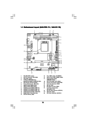
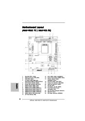
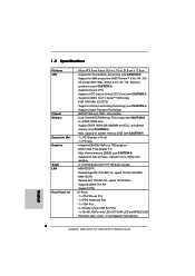
... Front Panel Audio Header (HD_AUDIO1, Lime) 24 ATX 12V Power Connector (ATX12V1) 25 AM3 CPU Socket 26 ATX Power Connector (ATXPWR1) 11 1.3 Motherboard Layout (N68-VGS3 FX / N68-VS3 FX) 26 USB 2.0 T: USB2 B: USB3 VGA1 PS2 Mouse PS2 Keyboard 1 2 3 17.8cm (7.0-in) Support 8-Core CPU 1 PS2_USB_PWR1 CPU_FAN1 1 USB_PWR2 DDR3_B1 (64 bit, 240-FpSin Bm8od0u0le) 4 DDR3_A1 (64 bit, 240...
... Front Panel Audio Header (HD_AUDIO1, Lime) 24 ATX 12V Power Connector (ATX12V1) 25 AM3 CPU Socket 26 ATX Power Connector (ATXPWR1) 11 1.3 Motherboard Layout (N68-VGS3 FX / N68-VS3 FX) 26 USB 2.0 T: USB2 B: USB3 VGA1 PS2 Mouse PS2 Keyboard 1 2 3 17.8cm (7.0-in) Support 8-Core CPU 1 PS2_USB_PWR1 CPU_FAN1 1 USB_PWR2 DDR3_B1 (64 bit, 240-FpSin Bm8od0u0le) 4 DDR3_A1 (64 bit, 240...
User Manual
Page 15
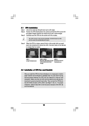
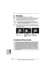
... it is necessary to install a larger heatsink and cooling fan to the CPU FAN connector (CPU_FAN1, see Page 11, No. 2). Carefully insert the CPU into the socket to secure the CPU. Make sure that the CPU and the heatsink are securely fastened and in place, press it firmly on...STEP 1: Lift Up The Socket Lever CPU Golden Triangle Socker Corner Small Triangle STEP 2 / STEP 3: Match The CPU Golden Triangle To The Socket Corner Small Triangle STEP 4: Push Down And Lock The Socket Lever 2.2 Installation of the CPU fan and the heatsink. 15 Then connect the CPU fan to dissipate heat. ...
... it is necessary to install a larger heatsink and cooling fan to the CPU FAN connector (CPU_FAN1, see Page 11, No. 2). Carefully insert the CPU into the socket to secure the CPU. Make sure that the CPU and the heatsink are securely fastened and in place, press it firmly on...STEP 1: Lift Up The Socket Lever CPU Golden Triangle Socker Corner Small Triangle STEP 2 / STEP 3: Match The CPU Golden Triangle To The Socket Corner Small Triangle STEP 4: Push Down And Lock The Socket Lever 2.2 Installation of the CPU fan and the heatsink. 15 Then connect the CPU fan to dissipate heat. ...
Quick Installation Guide
Page 2
Blue) 5 CPU Heatsink Retention Module 6 Primary IDE Connector (IDE1, Blue) 7 USB 2.0 Header (USB6_7, Blue) 8 USB 2.0 Header (USB4_5, Blue) 9 SATAII Connector (SATAII_2 (PORT 0.1)) 10 SATAII ...PCI Express x16 Slot (PCIE1) 23 Front Panel Audio Header (HD_AUDIO1, Lime) 24 ATX 12V Power Connector (ATX12V1) 25 AM3 CPU Socket 26 ATX Power Connector (ATXPWR1) 2 ASRock N68-VGS3 FX / N68-VS3 FX Motherboard Motherboard Layout (N68-VGS3 FX / N68-VS3 FX) English 1 PS2_USB_PWR1 Jumper 2 CPU Fan Connector (CPU_FAN1) 3 USB_PWR2 Jumper 4 2 x 240-pin DDR3 DIMM Slots (Dual Channel: DDR3_A1, DDR3_B1;
Blue) 5 CPU Heatsink Retention Module 6 Primary IDE Connector (IDE1, Blue) 7 USB 2.0 Header (USB6_7, Blue) 8 USB 2.0 Header (USB4_5, Blue) 9 SATAII Connector (SATAII_2 (PORT 0.1)) 10 SATAII ...PCI Express x16 Slot (PCIE1) 23 Front Panel Audio Header (HD_AUDIO1, Lime) 24 ATX 12V Power Connector (ATX12V1) 25 AM3 CPU Socket 26 ATX Power Connector (ATXPWR1) 2 ASRock N68-VGS3 FX / N68-VS3 FX Motherboard Motherboard Layout (N68-VGS3 FX / N68-VS3 FX) English 1 PS2_USB_PWR1 Jumper 2 CPU Fan Connector (CPU_FAN1) 3 USB_PWR2 Jumper 4 2 x 240-pin DDR3 DIMM Slots (Dual Channel: DDR3_A1, DDR3_B1;
Quick Installation Guide
Page 6
Support for Socket AM3+ processors (see CAUTION 2) - DX9.0 VGA, Pixel Shader 3.0 - resolution up to -Use USB 2.0 Ports - 1 x RJ-45 LAN Port with max. N68-VGS3 FX Realtek Giga PHY RTL8211CL, speed 10/100/1000 Mb/s - Supports UCC feature (Unlock CPU Core) (see CAUTION 5) -...slot - Max. HD Audio Jack: Line in , 21.6 cm x 17.8 cm - Supports 8-Core CPU - Micro ATX Form Factor: 8.5-in x 7.0-in / Front Speaker / Microphone English 6 ASRock N68-VGS3 FX / N68-VS3 FX Motherboard capacity of system memory: 8GB (see CAUTION 6) - Supports D-Sub with LED (ACT/LINK LED ...
Support for Socket AM3+ processors (see CAUTION 2) - DX9.0 VGA, Pixel Shader 3.0 - resolution up to -Use USB 2.0 Ports - 1 x RJ-45 LAN Port with max. N68-VGS3 FX Realtek Giga PHY RTL8211CL, speed 10/100/1000 Mb/s - Supports UCC feature (Unlock CPU Core) (see CAUTION 5) -...slot - Max. HD Audio Jack: Line in , 21.6 cm x 17.8 cm - Supports 8-Core CPU - Micro ATX Form Factor: 8.5-in x 7.0-in / Front Speaker / Microphone English 6 ASRock N68-VGS3 FX / N68-VS3 FX Motherboard capacity of system memory: 8GB (see CAUTION 6) - Supports D-Sub with LED (ACT/LINK LED ...
Quick Installation Guide
Page 12
... socket while you install the CPU into the socket to indicate that the CPU corner with the golden triangle matches the socket corner with each other. Carefully insert the CPU into the socket ...CPU FAN connector (CPU_FAN1, see Page 2, No. 2). Lever 90° Up STEP 1: Lift Up The Socket Lever CPU Golden Triangle Socker Corner Small Triangle STEP 2 / STEP 3: STEP 4: Match The CPU Golden Triangle Push Down And Lock To The Socket Corner Small The Socket Lever Triangle 2.2 Installation of the CPU fan and the heatsink. Step 2. English 12 ASRock N68-VGS3 FX / N68-VS3 FX...
... socket while you install the CPU into the socket to indicate that the CPU corner with the golden triangle matches the socket corner with each other. Carefully insert the CPU into the socket ...CPU FAN connector (CPU_FAN1, see Page 2, No. 2). Lever 90° Up STEP 1: Lift Up The Socket Lever CPU Golden Triangle Socker Corner Small Triangle STEP 2 / STEP 3: STEP 4: Match The CPU Golden Triangle Push Down And Lock To The Socket Corner Small The Socket Lever Triangle 2.2 Installation of the CPU fan and the heatsink. Step 2. English 12 ASRock N68-VGS3 FX / N68-VS3 FX...


