
User Manual
Page 3
... Motherboard Layout 13 1.5 I/O Panel 14 2 Installation 16 2.1 Screw Holes 16 2.2 Pre-installation Precautions 16 2.3 CPU Installation 17 2.4 Installation of Heatsink and CPU fan 19 2.5 Installation of Memory Modules (DIMM 20 2.6 Expansion Slots (PCI Express Slots 21 2.7 Jumpers Setup 22 2.8 Onboard Headers and Connectors 23 2.9 Driver Installation Guide 28 2.10 Installing Windows® 8 / 8 64-bit / 7 / 7 64-bit / VistaTM / VistaTM 64-bit / XP / XP 64-bit Without RAID Functions . 28 2.10.1 Installing Windows® XP / XP 64-bit Without RAID Functions 28 2.10.2 Installing Windows...
... Motherboard Layout 13 1.5 I/O Panel 14 2 Installation 16 2.1 Screw Holes 16 2.2 Pre-installation Precautions 16 2.3 CPU Installation 17 2.4 Installation of Heatsink and CPU fan 19 2.5 Installation of Memory Modules (DIMM 20 2.6 Expansion Slots (PCI Express Slots 21 2.7 Jumpers Setup 22 2.8 Onboard Headers and Connectors 23 2.9 Driver Installation Guide 28 2.10 Installing Windows® 8 / 8 64-bit / 7 / 7 64-bit / VistaTM / VistaTM 64-bit / XP / XP 64-bit Without RAID Functions . 28 2.10.1 Installing Windows® XP / XP 64-bit Without RAID Functions 28 2.10.2 Installing Windows...

User Manual
Page 4
... 3.1.1 UEFI Menu Bar 40 3.1.2 Navigation Keys 41 3.2 Main Screen 41 3.3 OC Tweaker Screen 43 3.4 Advanced Screen 47 3.4.1 CPU Configuration 48 3.4.2 North Bridge Configuration 50 3.4.3 South Bridge Configuration 51 3.4.4 Storage Configuration 52 3.4.5 Intel(R) Rapid Start Technology 53 3.4.6 Intel(R) Smart Connect Technology 54 3.4.7 Super IO Configuration 55 3.4.8 ACPI Configuration 56 3.4.9 USB Configuration 57 3.5 Tool 58 3.6 Hardware Health Event Monitoring Screen 60 3.7 Boot Screen 61 3.8 Security Screen 63 3.9 Exit Screen 64 4 Software Support 65 4.1 Install Operating...
... 3.1.1 UEFI Menu Bar 40 3.1.2 Navigation Keys 41 3.2 Main Screen 41 3.3 OC Tweaker Screen 43 3.4 Advanced Screen 47 3.4.1 CPU Configuration 48 3.4.2 North Bridge Configuration 50 3.4.3 South Bridge Configuration 51 3.4.4 Storage Configuration 52 3.4.5 Intel(R) Rapid Start Technology 53 3.4.6 Intel(R) Smart Connect Technology 54 3.4.7 Super IO Configuration 55 3.4.8 ACPI Configuration 56 3.4.9 USB Configuration 57 3.5 Tool 58 3.6 Hardware Health Event Monitoring Screen 60 3.7 Boot Screen 61 3.8 Security Screen 63 3.9 Exit Screen 64 4 Software Support 65 4.1 Install Operating...
User Manual
Page 5
... H61M-PS4 / H61M-VG4 / H61M-VS4 Motherboard (Micro ATX Form Factor) ASRock H61M-PS4 / H61M-VG4 / H61M-VS4 Quick Installation Guide ASRock H61M-PS4 / H61M-VG4 / H61M-VS4 Support CD 2 x Serial ATA (SATA) Data Cables (Optional) 1 x I/O Panel Shield ASRock Reminds You... It delivers excellent performance with robust design conforming to ASRock's commitment to BIOS setup and information of the Support CD. Because the motherboard specifications and the BIOS software might be updated, the content of the motherboard and stepby-step guide to AHCI mode. 5 Chapter 3 and 4 contain the configuration...
... H61M-PS4 / H61M-VG4 / H61M-VS4 Motherboard (Micro ATX Form Factor) ASRock H61M-PS4 / H61M-VG4 / H61M-VS4 Quick Installation Guide ASRock H61M-PS4 / H61M-VG4 / H61M-VS4 Support CD 2 x Serial ATA (SATA) Data Cables (Optional) 1 x I/O Panel Shield ASRock Reminds You... It delivers excellent performance with robust design conforming to ASRock's commitment to BIOS setup and information of the Support CD. Because the motherboard specifications and the BIOS software might be updated, the content of the motherboard and stepby-step guide to AHCI mode. 5 Chapter 3 and 4 contain the configuration...
User Manual
Page 6
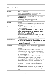
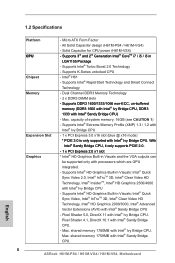
... CPU - Supports Intel® HD Graphics Built-in Visuals: Intel® Quick Sync Video 2.0, Intel® InTruTM 3D, Intel® Clear Video HD Technology, Intel® InsiderTM, Intel® HD Graphics 2500/4000 with Intel® Sandy Bridge CPU - 1.2 Specifications Platform CPU Chipset Memory Expansion Slot Graphics - Micro ATX Form Factor - All Solid Capacitor design (H61M-PS4 / H61M-VG4) - Supports Intel® Turbo Boost 2.0 Technology - Intel® H61 - Dual Channel DDR3 Memory Technology - 2 x DDR3 DIMM slots...
... CPU - Supports Intel® HD Graphics Built-in Visuals: Intel® Quick Sync Video 2.0, Intel® InTruTM 3D, Intel® Clear Video HD Technology, Intel® InsiderTM, Intel® HD Graphics 2500/4000 with Intel® Sandy Bridge CPU - 1.2 Specifications Platform CPU Chipset Memory Expansion Slot Graphics - Micro ATX Form Factor - All Solid Capacitor design (H61M-PS4 / H61M-VG4) - Supports Intel® Turbo Boost 2.0 Technology - Intel® H61 - Dual Channel DDR3 Memory Technology - 2 x DDR3 DIMM slots...
User Manual
Page 7
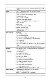
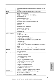
... Keyboard Port - 1 x Serial Port: COM1 (H61M-PS4) - 1 x Parallel Port (ECP/EPP support) (H61M-PS4) - 1 x D-Sub Port - 4 x USB 2.0 Ports - 1 x RJ-45 LAN Port with max. Supports LAN Cable Detection - ACPI 1.1 Compliance Wake Up Events 7 PCIE x1 Gigabit LAN 10/100/1000 Mb/s - Supports PXE I /O Storage Connector BIOS Feature - HD Audio Jack: Line in/Front Speaker/Microphone - 4 x SATA2 3.0 Gb/s connectors, support NCQ, AHCI and Hot Plug functions - 1 x IR header - 1 x Power LED header - 1 x Chassis Intrusion header - 1 x LPC/TPM header - 1 x CPU Fan connectors (4-pin) - 1 x Chassis Fan...
... Keyboard Port - 1 x Serial Port: COM1 (H61M-PS4) - 1 x Parallel Port (ECP/EPP support) (H61M-PS4) - 1 x D-Sub Port - 4 x USB 2.0 Ports - 1 x RJ-45 LAN Port with max. Supports LAN Cable Detection - ACPI 1.1 Compliance Wake Up Events 7 PCIE x1 Gigabit LAN 10/100/1000 Mb/s - Supports PXE I /O Storage Connector BIOS Feature - HD Audio Jack: Line in/Front Speaker/Microphone - 4 x SATA2 3.0 Gb/s connectors, support NCQ, AHCI and Hot Plug functions - 1 x IR header - 1 x Power LED header - 1 x Chassis Intrusion header - 1 x LPC/TPM header - 1 x CPU Fan connectors (4-pin) - 1 x Chassis Fan...
User Manual
Page 9
... floppy diskette or other complicated flash utility. Please be noted that cannot be used under Windows® OS 32-bit CPU. This convenient BIOS update tool allows you can press the key during the shutdown and startup process, Instant Boot allows you can update your USB flash drive, floppy disk or hard drive, then you to shorten boot up time. In Hardware Monitor, it shows the fan speed and temperature for your system. In Fan Control...
... floppy diskette or other complicated flash utility. Please be noted that cannot be used under Windows® OS 32-bit CPU. This convenient BIOS update tool allows you can press the key during the shutdown and startup process, Instant Boot allows you can update your USB flash drive, floppy disk or hard drive, then you to shorten boot up time. In Hardware Monitor, it shows the fan speed and temperature for your system. In Fan Control...
User Manual
Page 13
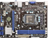
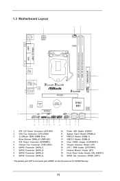
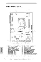
...1 ATX 12V Power Connector (ATX12V1) 2 CPU Fan Connector (CPU_FAN1) 3 2 x 240-pin DDR3 DIMM Slots (Dual Channel: DDR3_A1, DDR3_B1) 4 ATX Power Connector (ATXPWR1) 5 Chassis Fan Connector (CHA_FAN1) 6 SATA2 Connector (SATA_1) 7 SATA2 Connector (SATA_0) 8 SATA2 Connector (SATA_3) 9 SATA2 Connector (SATA_2) 10 Power LED Header (PLED1) 11 System Panel Header (PANEL1) 12 USB 2.0 Header (USB6_7) 13 USB 2.0 Header (USB4_5) 14 Clear CMOS Jumper (CLRCMOS1) 15 Chassis Intrusion Header (CI1) 16 LPC / TPM Header (LPC/TPM1) 17 Infrared Module Header (IR1) 18 Front Panel Audio Header (HD_AUDIO1) 19 SPDIF...
...1 ATX 12V Power Connector (ATX12V1) 2 CPU Fan Connector (CPU_FAN1) 3 2 x 240-pin DDR3 DIMM Slots (Dual Channel: DDR3_A1, DDR3_B1) 4 ATX Power Connector (ATXPWR1) 5 Chassis Fan Connector (CHA_FAN1) 6 SATA2 Connector (SATA_1) 7 SATA2 Connector (SATA_0) 8 SATA2 Connector (SATA_3) 9 SATA2 Connector (SATA_2) 10 Power LED Header (PLED1) 11 System Panel Header (PANEL1) 12 USB 2.0 Header (USB6_7) 13 USB 2.0 Header (USB4_5) 14 Clear CMOS Jumper (CLRCMOS1) 15 Chassis Intrusion Header (CI1) 16 LPC / TPM Header (LPC/TPM1) 17 Infrared Module Header (IR1) 18 Front Panel Audio Header (HD_AUDIO1) 19 SPDIF...
User Manual
Page 28
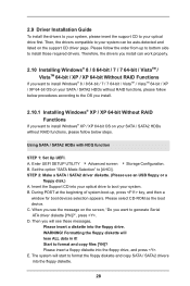
... the Support CD into the floppy diskette. 28 Please select CD-ROM as the boot device. Then you want to install Windows® XP / XP 64-bit OS on your optical drive first. WARNING! E. Enter UEFI SETUP UTILITY Advanced screen Storage Configuration. STEP 2: Make a SATA / SATA2 driver diskette. (Please use an USB floppy or a floppy disk.) A. B. When you want to generate Serial ATA driver diskette [YN]?", press . Formatting the floppy diskette will start to format the floppy diskette...
... the Support CD into the floppy diskette. 28 Please select CD-ROM as the boot device. Then you want to install Windows® XP / XP 64-bit OS on your optical drive first. WARNING! E. Enter UEFI SETUP UTILITY Advanced screen Storage Configuration. STEP 2: Make a SATA / SATA2 driver diskette. (Please use an USB floppy or a floppy disk.) A. B. When you want to generate Serial ATA driver diskette [YN]?", press . Formatting the floppy diskette will start to format the floppy diskette...

User Manual
Page 48
... Support Use this technology, such as Microsoft® Windows® XP / VistaTM / 7 / 8 is required. The default value is an enhancement 48 No-Execute Memory Protection No-Execution (NX) Memory Protection Technology is [Auto]. 3.4.1 CPU Configuration Intel Hyper Threading Technology To enable this feature, a computer system with an Intel processor that supports Hyper-Threading technology and an operating system that includes optimization for this to enable or disable CPU C3 (ACPI...
... Support Use this technology, such as Microsoft® Windows® XP / VistaTM / 7 / 8 is required. The default value is an enhancement 48 No-Execute Memory Protection No-Execution (NX) Memory Protection Technology is [Auto]. 3.4.1 CPU Configuration Intel Hyper Threading Technology To enable this feature, a computer system with an Intel processor that supports Hyper-Threading technology and an operating system that includes optimization for this to enable or disable CPU C3 (ACPI...

User Manual
Page 50
...; Virtualization Technology for Directed I/O). VT-d Use this feature is [Auto]. 3.4.2 North Bridge Configuration Primary Graphics Adapter This allows you to enable or disable Render Standby by Internal Graphics Device. The default value is [Enabled]. 50 The default value is [PCI Express]. Render Standby Use this option. The default value is [Enabled]. The default value is [Auto]. If you install the PCI Express card under Windows® XP / VistaTM OS, please disable this to select [Onboard] or [PCI Express] as the boot graphic adapter...
...; Virtualization Technology for Directed I/O). VT-d Use this feature is [Auto]. 3.4.2 North Bridge Configuration Primary Graphics Adapter This allows you to enable or disable Render Standby by Internal Graphics Device. The default value is [Enabled]. 50 The default value is [PCI Express]. Render Standby Use this option. The default value is [Enabled]. The default value is [Auto]. If you install the PCI Express card under Windows® XP / VistaTM OS, please disable this to select [Onboard] or [PCI Express] as the boot graphic adapter...
User Manual
Page 57
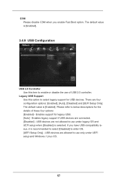
... to use under UEFI setup and Windows / Linux OS. 57 Enables support for USB devices. If you enable Fast Boot option. USB devices are four configuration options: [Enabled], [Auto], [Disabled] and [UEFI Setup Only]. Legacy USB Support Use this item to enable or disable the use only under legacy OS and UEFI setup when [Disabled] is [Enabled]. 3.4.9 USB Configuration USB 2.0 Controller Use this option to enter OS. [UEFI Setup Only] - USB devices are connected. [Disabled] - CSM Please disable CSM when you have USB compatibility issue, it is [Enabled]. The default value...
... to use under UEFI setup and Windows / Linux OS. 57 Enables support for USB devices. If you enable Fast Boot option. USB devices are four configuration options: [Enabled], [Auto], [Disabled] and [UEFI Setup Only]. Legacy USB Support Use this item to enable or disable the use only under legacy OS and UEFI setup when [Disabled] is [Enabled]. 3.4.9 USB Configuration USB 2.0 Controller Use this option to enter OS. [UEFI Setup Only] - USB devices are connected. [Disabled] - CSM Please disable CSM when you have USB compatibility issue, it is [Enabled]. The default value...
User Manual
Page 60
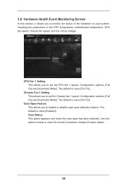
... your system, including the parameters of previous chassis intrusion status. 60 Configuration options: [Full On] and [Automatic Mode]. Use this section, it allows you to enable or disable case open has been detected. Chassis Fan 1 Setting This allows you to set the CPU fan 1 speed. CPU Fan 1 Setting This allows you to set the Chassis fan 1 speed. 3.6 Hardware Health Event Monitoring Screen In this option to keep or clear the record of the CPU temperature, motherboard temperature, CPU fan speed, chassis fan speed, and the critical voltage.
... your system, including the parameters of previous chassis intrusion status. 60 Configuration options: [Full On] and [Automatic Mode]. Use this section, it allows you to enable or disable case open has been detected. Chassis Fan 1 Setting This allows you to set the CPU fan 1 speed. CPU Fan 1 Setting This allows you to set the Chassis fan 1 speed. 3.6 Hardware Health Event Monitoring Screen In this option to keep or clear the record of the CPU temperature, motherboard temperature, CPU fan speed, chassis fan speed, and the critical voltage.
User Manual
Page 65
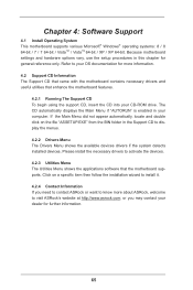
... BIN folder in the Support CD to your OS documentation for further information. 65 Please install the necessary drivers to visit ASRock's website at http://www.asrock.com; Chapter 4: Software Support 4.1 Install Operating System This motherboard supports various Microsoft® Windows® operating systems: 8 / 8 64-bit / 7 / 7 64-bit / VistaTM / VistaTM 64-bit / XP / XP 64-bit. Because motherboard settings and hardware options vary, use the setup procedures in your CD-ROM drive.
... BIN folder in the Support CD to your OS documentation for further information. 65 Please install the necessary drivers to visit ASRock's website at http://www.asrock.com; Chapter 4: Software Support 4.1 Install Operating System This motherboard supports various Microsoft® Windows® operating systems: 8 / 8 64-bit / 7 / 7 64-bit / VistaTM / VistaTM 64-bit / XP / XP 64-bit. Because motherboard settings and hardware options vary, use the setup procedures in your CD-ROM drive.
Quick Installation Guide
Page 2
...1 ATX 12V Power Connector (ATX12V1) 2 CPU Fan Connector (CPU_FAN1) 3 2 x 240-pin DDR3 DIMM Slots (Dual Channel: DDR3_A1, DDR3_B1) 4 ATX Power Connector (ATXPWR1) 5 Chassis Fan Connector (CHA_FAN1) 6 SATA2 Connector (SATA_1) 7 SATA2 Connector (SATA_0) 8 SATA2 Connector (SATA_3) 9 SATA2 Connector (SATA_2) 10 Power LED Header (PLED1) 11 System Panel Header (PANEL1) 12 USB 2.0 Header (USB6_7) 13 USB 2.0 Header (USB4_5) 14 Clear CMOS Jumper (CLRCMOS1) 15 Chassis Intrusion Header (CI1) 16 LPC / TPM Header (LPC/TPM1) 17 Infrared Module Header (IR1) 18 Front Panel Audio Header (HD_AUDIO1) 19 SPDIF...
...1 ATX 12V Power Connector (ATX12V1) 2 CPU Fan Connector (CPU_FAN1) 3 2 x 240-pin DDR3 DIMM Slots (Dual Channel: DDR3_A1, DDR3_B1) 4 ATX Power Connector (ATXPWR1) 5 Chassis Fan Connector (CHA_FAN1) 6 SATA2 Connector (SATA_1) 7 SATA2 Connector (SATA_0) 8 SATA2 Connector (SATA_3) 9 SATA2 Connector (SATA_2) 10 Power LED Header (PLED1) 11 System Panel Header (PANEL1) 12 USB 2.0 Header (USB6_7) 13 USB 2.0 Header (USB4_5) 14 Clear CMOS Jumper (CLRCMOS1) 15 Chassis Intrusion Header (CI1) 16 LPC / TPM Header (LPC/TPM1) 17 Infrared Module Header (IR1) 18 Front Panel Audio Header (HD_AUDIO1) 19 SPDIF...
Quick Installation Guide
Page 5
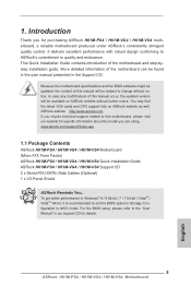
... are using. For the BIOS setup, please refer to change without further notice. Because the motherboard specifications and the BIOS software might be available on ASRock website as well. In case any modifications of the motherboard and step-bystep installation guide. www.asrock.com/support/index.asp 1.1 Package Contents ASRock H61M-PS4 / H61M-VG4 / H61M-VS4 Motherboard (Micro ATX Form Factor) ASRock H61M-PS4 / H61M-VG4 / H61M-VS4 Quick Installation Guide ASRock H61M-PS4 / H61M-VG4 / H61M-VS4 Support CD 2 x Serial ATA (SATA) Data Cables (Optional) 1 x I/O Panel Shield ASRock Reminds...
... are using. For the BIOS setup, please refer to change without further notice. Because the motherboard specifications and the BIOS software might be available on ASRock website as well. In case any modifications of the motherboard and step-bystep installation guide. www.asrock.com/support/index.asp 1.1 Package Contents ASRock H61M-PS4 / H61M-VG4 / H61M-VS4 Motherboard (Micro ATX Form Factor) ASRock H61M-PS4 / H61M-VG4 / H61M-VS4 Quick Installation Guide ASRock H61M-PS4 / H61M-VG4 / H61M-VS4 Support CD 2 x Serial ATA (SATA) Data Cables (Optional) 1 x I/O Panel Shield ASRock Reminds...
Quick Installation Guide
Page 6
... Bridge CPU - Dual Channel DDR3 Memory Technology - 2 x DDR3 DIMM slots - Max. Supports Intel® HD Graphics Built-in LGA1155 Package - Max. Supports 3rd and 2nd Generation Intel® CoreTM i7 / i5 / i3 in Visuals: Intel® Quick Sync Video 2.0, Intel® InTruTM 3D, Intel® Clear Video HD Technology, Intel® InsiderTM, Intel® HD Graphics 2500/4000 with Intel® Sandy Bridge CPU. 6 ASRock H61M-PS4 / H61M-VG4 / H61M-VS4 Motherboard English Supports...
... Bridge CPU - Dual Channel DDR3 Memory Technology - 2 x DDR3 DIMM slots - Max. Supports Intel® HD Graphics Built-in LGA1155 Package - Max. Supports 3rd and 2nd Generation Intel® CoreTM i7 / i5 / i3 in Visuals: Intel® Quick Sync Video 2.0, Intel® InTruTM 3D, Intel® Clear Video HD Technology, Intel® InsiderTM, Intel® HD Graphics 2500/4000 with Intel® Sandy Bridge CPU. 6 ASRock H61M-PS4 / H61M-VG4 / H61M-VS4 Motherboard English Supports...
Quick Installation Guide
Page 7
...Storage Connector BIOS Feature - HD Audio Jack: Line in/Front Speaker/Microphone - 4 x SATA2 3.0 Gb/s connectors, support NCQ, AHCI and Hot Plug functions - 1 x IR header - 1 x Power LED header - 1 x Chassis Intrusion header - 1 x LPC/TPM header - 1 x CPU Fan connectors (4-pin) - 1 x Chassis Fan connector (4-pin) - 1 x 24 pin ATX power connector - 1 x 4 pin 12V power connector - 1 x Front panel audio connector - 1 x SPDIF Out connector - 2 x USB 2.0 headers (support 4 USB 2.0 ports) - 32Mb AMI UEFI Legal BIOS with LED (ACT/LINK LED and SPEED LED) - Realtek PCIE x1 LAN 8105E - Supports Wake...
...Storage Connector BIOS Feature - HD Audio Jack: Line in/Front Speaker/Microphone - 4 x SATA2 3.0 Gb/s connectors, support NCQ, AHCI and Hot Plug functions - 1 x IR header - 1 x Power LED header - 1 x Chassis Intrusion header - 1 x LPC/TPM header - 1 x CPU Fan connectors (4-pin) - 1 x Chassis Fan connector (4-pin) - 1 x 24 pin ATX power connector - 1 x 4 pin 12V power connector - 1 x Front panel audio connector - 1 x SPDIF Out connector - 2 x USB 2.0 headers (support 4 USB 2.0 ports) - 32Mb AMI UEFI Legal BIOS with LED (ACT/LINK LED and SPEED LED) - Realtek PCIE x1 LAN 8105E - Supports Wake...
Quick Installation Guide
Page 10
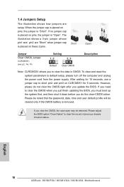
... on pins, the jumper is "Short". To clear and reset the system parameters to clear the record of previous chassis intrusion status. If you update the BIOS. Please be noted that the password, date, time and user default profile will be detected. English 10 ASRock H61M-PS4 / H61M-VG4 / H61M-VS4 Motherboard Please adjust the BIOS option "Clear Status" to default setup, please turn off the computer and unplug the power cord from the power supply. 1.4 Jumpers Setup The...
... on pins, the jumper is "Short". To clear and reset the system parameters to clear the record of previous chassis intrusion status. If you update the BIOS. Please be noted that the password, date, time and user default profile will be detected. English 10 ASRock H61M-PS4 / H61M-VG4 / H61M-VS4 Motherboard Please adjust the BIOS option "Clear Status" to default setup, please turn off the computer and unplug the power cord from the power supply. 1.4 Jumpers Setup The...
Quick Installation Guide
Page 14
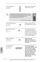
... 24-pin ATX power connector, 12 24 it can securely store keys, digital certificates, passwords, and data. A TPM system also helps enhance network security, protects digital identities, and ensures platform integrity. 14 ASRock H61M-PS4 / H61M-VG4 / H61M-VS4 Motherboard To use the 20-pin ATX power supply, please plug your power supply along with chassis intrusion detection design. Chassis Intrusion Header (2-pin CI1) (see p.2, No. 15) 1 GND Signal SPDIF Out Connector (2-pin SPDIF_OUT1) (see p.2, No. 16 This connector supports...
... 24-pin ATX power connector, 12 24 it can securely store keys, digital certificates, passwords, and data. A TPM system also helps enhance network security, protects digital identities, and ensures platform integrity. 14 ASRock H61M-PS4 / H61M-VG4 / H61M-VS4 Motherboard To use the 20-pin ATX power supply, please plug your power supply along with chassis intrusion detection design. Chassis Intrusion Header (2-pin CI1) (see p.2, No. 15) 1 GND Signal SPDIF Out Connector (2-pin SPDIF_OUT1) (see p.2, No. 16 This connector supports...
Quick Installation Guide
Page 15
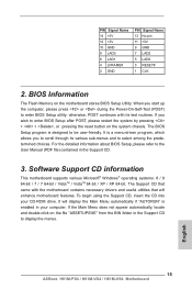
... enabled in your CD-ROM drive. It will enhance motherboard features. English 15 ASRock H61M-PS4 / H61M-VG4 / H61M-VS4 Motherboard When you wish to select among the predetermined choices. If the Main Menu does not appear automatically, locate and double-click on the motherboard stores BIOS Setup Utility. otherwise, POST continues with the motherboard contains necessary drivers and useful utilities that will display the Main Menu automatically if "AUTORUN" is designed to enter BIOS Setup utility; BIOS Information The Flash Memory...
... enabled in your CD-ROM drive. It will enhance motherboard features. English 15 ASRock H61M-PS4 / H61M-VG4 / H61M-VS4 Motherboard When you wish to select among the predetermined choices. If the Main Menu does not appear automatically, locate and double-click on the motherboard stores BIOS Setup Utility. otherwise, POST continues with the motherboard contains necessary drivers and useful utilities that will display the Main Menu automatically if "AUTORUN" is designed to enter BIOS Setup utility; BIOS Information The Flash Memory...


